PAPAN SKOR BOLA BASKET NIRKABEL
DENGAN MENGGUNAKAN TEKNOLOGI
XBEE 802.15.4
Anasthasia Giovanny
Program Studi Sistem Komputer, Universitas Bina Nusantara, gio.anasthasia@gmail.com
Eva Ayuning Cahya
Program Studi Sistem Komputer, Universitas Bina Nusantara, cahyaevaayuning@gmail.com
Robby Saleh
Program Studi Sistem Komputer, Universitas Bina Nusantara, robby.saleh@gmail.com
ABSTRAK
Saat ini media kabel masih banyak digunakan pada sistem papan nilai. Walaupun ada yang tanpa kabel maka harganya relatif mahal. Papan nilai yang dibuat adalah papan nilai yang berfungsi untuk menampilkan poin dari pertandingan olahraga basket. Papan nilai dibuat semi otomatis atau membutuhkan operator untuk melakukan pengendalian. Papan nilai ini menggunakan XBEE sebagai media komunikasi tanpa kabel dan Arduino Mega2560 sebagai unit pengontrol atau mikrokontrolernya. Alat ini membutuhkan push button sebagai penginput dan display berupa seven segment.Papan nilai terdiri dari display game sebagai penampil babak, display score sebagai penampil nilai untuk masing-masing tim, display foul sebagai penampil angka pelanggaran yang dilakukan setiap tim, display time sebagai penampil waktu jalannya pertandingan dan display shot clock sebagai penampil twenty four second countdown pada pertandingan bola basket. Setelah dilakukan percobaan, hasilnya papan nilai berfungsi dengan baik dimana respon dari transmitter dan receiver XBEE sudah berjalan dengan baik. Pengujian respon di indoor mencapai 40 meter dan outdoor 90 meter.
Kata Kunci : XBEE, Papan nilai basket, Arduino Mega2560
PENDAHULUAN
Scoreboard atau papan nilai digunakan dalam pertandingan olahraga sebagai penampil hasil dari
suatu pertandingan. Scoreboard khususnya pada pertandingan bola basket biasanya tidak hanya menampilkan nilai dari hasil pertandingan, tapi juga menampilkan waktu pertandingan, jumlah babak,
shot clock, dan jumlah pelanggaran yang dihasilkan pemain saat pertandingan berlangsung.
Scoreboard yang dijual di Indonesia kebanyakan masih menggunakan kabel sebagai media
transmisi pada saat melakukan penginputan data ke penampil. Biasanya media penginputan berupa
remote yang koneksinya menggunakan kabel ke penampil. Remote dipegang dengan jarak sesuai panjang
kabel dimana ini sangat tidak praktis. Ruang gerak pemegang remote juga tidak leluasa karena remote tersambung dengan kabel.
Untuk itu penulis berinisiatif untuk memanfaatkan teknologi wireless yaitu XBEE agar lebih
fleksible saat digunakan. Karena dengan menggunakan XBEE, remote tidak perlu menggunakan kabel
lagi dan akan tersambung secara wireless dan tentunya akan mengurangi biaya juga. XBEE menggunakan protokol jaringan IEEE 802.15.4 yang bekerja pada frekuensi 2,4GHz.
Pada tahun 2012 di Korea Selatan, XBEE diajukan untuk mendukung pengontrolan jaringan rumah. Dimana XBEE digunakan sebagai remote untuk memonitor dan mengontrol sistem jaringan yang ada di rumah (Hwang, Yu, 2012).
Di bidang kesehatan XBEE juga sudah digunakan sebagai alat kontrol dan monitor untuk mengirim data physiological yang dimiliki seseorang ke sebuah PC yang sudah dipasang XBEE receiver lalu nantinya akan dikirim melalui sms ke telpon genggam petugas medis. Sinyal yang dikirim oleh XBEE transmitter berisi data denyut jantung dan tekanan darah dari seseorang. Jadi petugas bisa tetap mengetahui keadaan pasiennya setiap saat tanpa harus datang ke tempat pasien itu berada (Krishna, Priya, 2012).
Di India teknologi XBEE digunakan sebagai pengontrol tingkat pencemaran udara. XBEE disini digunakan untuk mengirim data pencemaran udara tiap harinya secara real-time ke server pengumpul data, lalu nantinya akan ditampilkan di internet (Chourasia, Washimkar, 2012).
Pemanfaatan XBEE untuk fasilitas umum juga dibuat oleh 2 engineer dari Italy dan Polandia. Mereka membuat Intelligent wireless street lighting system, dengan XBEE sebagai penyambung antara lampu jalan 1 dengan lampu jalan yang lainnya. Sistem mereka memfungsikan XBEE sebagai pengganti kabel sebagai penyambung lampu-lampu jalan pada umumnya (Leccese, Leonowicz, 2009).
Peran XBEE nampaknya belum berhenti sampai disitu. Pengajuan penggunaan XBEE sebagai monitoring power di suatu pabrik juga dilakukan di India. Mereka menggunakan XBEE sebagai pengontrol dalam menyalakan dan mematikan listrik di mesin pabrik tanpa terkendala jarak, atau dengan kata lain untuk mengontrol 1 mesin pabrik nantinya hanya akan dimonitor oleh PC yang sudah tersambung dengan XBEE transmitter dan mesin yang hendak dikontrol sudah dipasang XBEE receiver (Raut, Malik, 2011).
Begitu banyaknya engineer yang memanfaatkan XBEE di segala bidang kehidupan mendorong kami untuk memanfaatkan XBEE di bidang olahraga. Dalam penelitian ini kami akan mencoba menggunakan XBEE sebagai transmitter dan receiver pada sistem scoreboard. Dimana nantinya kami akan menggunakan 2 modul XBEE yaitu XBEE transmitter dan XBEE receiver. XBEE transmitter akan diletakkan di remote untuk mengirim data ke XBEE receiver yang akan diletakkan di scoreboard.
Untuk dapat menjalankan XBEE transmitter dan receiver sesuai dengan instruksi yang diinginkan maka diperlukan pengontrol, disini kami menggunakan dua buah mikrokontroler Arduino, dan masing-masing mikrokontroler akan dipasangi dengan XBEE transmitter dan receiver.
METODE PENELITIAN
Metode yang dilakukan oleh penulis adalah pertama mengumpulkan informasi dan sumber ilmu dari literature-literature yang ada dan mencari informasi melalui internet yang berhubungan dengan Scoreboard. Setelah itu penulis membuat Scoreboard itu sendiri. Sistem terdiri dari 2 modul yakni
transmitter dan receiver. Modul transmitter berupa remote yang di dalamnya terdapat Arduino Mega2560
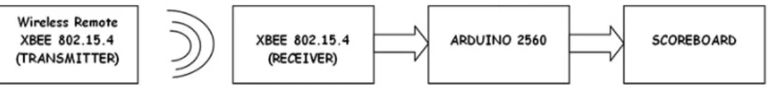
yang berfungsi sebagai mikrokontroler dan XBEE sebagai pengirim data. Pada modul receiver terdapat 15 seven segment yang berfungsi sebagai display scoreboard. Secara umum blok diagram dari sistem adalah sebagai berikut.
Blok diagram di atas menggambarkan sistem yang dibangun, terbagi menjadi 3 bagian, input, proses dan output. Dimana input sistem adalah wireless remote yang didalamnya terdapat XBEE
transmitter dan sebuah mikrokontroler. Saat transmitter mengirim data maka XBEE receiver yang
terhubung ke mikrokontroler receiver akan menerima data dan memproses sesuai program yang sudah dimasukkan sebelumnya dan menghasilkan output yaitu mengubah urutan angka pada Display
scoreboard. Mikrokontroler pada transmitter akan menunggu input dari push button yang sudah di
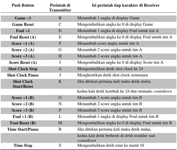
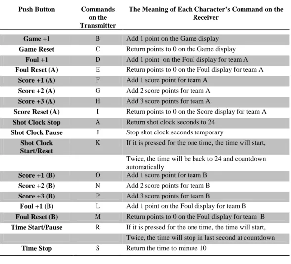
inisialisasikan di program berupa perintah A sampai S dimana isi perintah-perintah karakter tersebut terletak di mikrokontroler receiver. Jumlah push button itu sendiri sudah mewakilkan jumlah karakter setiap perintah, saat menekan push button B maka perintah untuk menambah angka game akan dikirim dan di mikrokontroler receiver terlebih dahulu akan dicari lalu setelah perintah tersebut ditemukan barulah diproses, setelah itu angka pada display game akan bertambah 1. Perintah dan karakter yang mewakilinya bisa dilihat di tabel di bawah.
Tabel 1. Inisialisasi Karakter pada Push Button
Berikut adalah diagram alir pengiriman dan penerimaan data yang dilakukan XBEE sesuai perintah yang dimasukkan :
Push Button Perintah di
Transmitter
Isi perintah tiap karakter di Receiver
Game +1 B Menambah 1 angka di display Game
Game Reset C Mengembalikan angka ke 0 di display Game
Foul +1 D Menambah 1 angka di display Foul untuk tim A
Foul Reset (A) E Mengembalikan angka ke 0 di display Foul untuk tim A
Score +1 (A) F Menambah score angka untuk tim A
Score +2 (A) G Menambah 2 score angka untuk tim A
Score +3 (A) H Menambah 3 score angka untuk tim A
Score Reset (A) I Mengembalikan angke ke 0 di display Score tim A
Shot Clock Stop A Mengembalikan detik shot clock ke 24
Shot Clock Pause J Menghentikan detik shot clock sementara
Shot Clock Start/Reset
K Jika ditekan pertama kali maka detik mulai,
kedua kali detik kembali ke 24 dan otomatis countdown
Score +1 (B) O Menambah 1 score angka untuk tim B
Score +2 (B) N Menambah 2 score angka untuk tim B
Score +3 (B) P Menambah 3 score angka untuk tim B
Foul +1 (B) L Menambah 1 angka di display Foul untuk tim B
Foul Reset (B) M Mengembalikan angka ke 0 di display Foul untuk tim B
Time Start/Pause R Jika ditekan pertama kali maka detik mulai,
kedua kali detik berhenti di detik terakhir saat
countdown
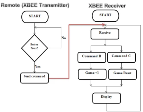
Gambar 2. Diagram Alir Proses Transmit dan Receive (Game)
Gambar 2 adalah diagram alir pengiriman dan penerimaan data untuk menambah angka di display game dan untuk mengulang angka kembali 0 yakni dengan reset.
Gambar 3. Diagram Alir Proses Transmit dan Receive (Foul)
Gambar 3 adalah diagram alir pengiriman dan penerimaan data untuk menambah angka foul pada display dan untuk mengulang angka kembali 0 yakni dengan reset.
Gambar 4. Diagram Alir Proses Transmit dan Receive (Score)
Gambar 4 adalah diagram alir pengiriman dan penerimaan data untuk menambah angka score pada
display. Terdapat 4 perintah pada masing-masing karakter yakni menambah angka 1, 2, dan 3 lalu
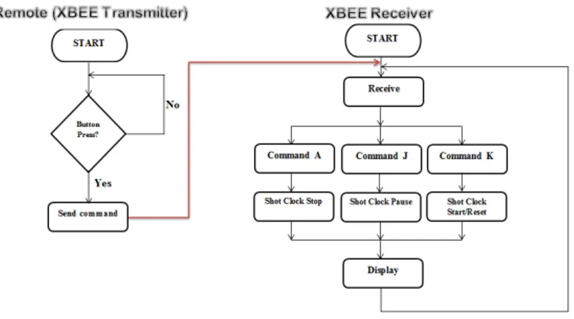
Gambar 5. Diagram Alir Proses Transmit dan Receive (Shot Clock)
Gambar 5 adalah diagram alir pengiriman dan penerimaan data untuk mengatur display shot clock. Terdapat 3 perintah yang diwakili masing-masing karakter yakni stop, pause, start/reset.
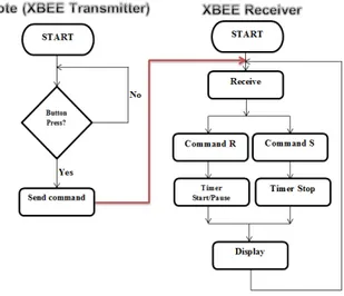
Gambar 6. Diagram Alir Proses Transmit dan Receive (Time)
Gambar 6 adalah diagram alir pengiriman dan penerimaan data untuk mengatur display time. Terdapat 2 perintah yang diwakili masing-masing karakter yakni start/pause dan stop.
Pengujian yang dilakukan diantaranya adalah, pengujian data precision untuk mengetahui apakah push button sudah berfungsi sesuai dengan fungsinya masing-masing atau belum, kedua pengujian penekanan 2 push button secara bersamaan, lalu ketiga pengujian respon modul XBEE dan keempat pengujian synchronization untuk mengetahui apakah detik dari shot clock pada scoreboard sudah sinkron dengan detik pada jam yang sudah ada atau belum. Terakhir adalah pengujian kuat sinyal pada modul XBEE untuk mengetahui jarak terjauh XBEE untuk menerima sinyal.
HASIL DAN BAHASAN
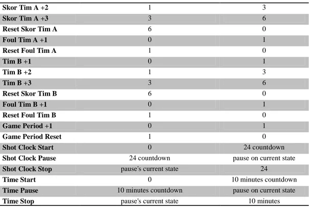
Tabel 2. Hasil Pengujian Data PrecisionButton Current Number on Scoreboard Final Number on
Scoreboard
Skor Tim A +2 1 3
Skor Tim A +3 3 6
Reset Skor Tim A 6 0
Foul Tim A +1 0 1
Reset Foul Tim A 1 0
Tim B +1 0 1
Tim B +2 1 3
Tim B +3 3 6
Reset Skor Tim B 6 0
Foul Tim B +1 0 1
Reset Foul Tim B 1 0
Game Period +1 0 1
Game Period Reset 1 0
Shot Clock Start 0 24 countdown
Shot Clock Pause 24 countdown pause on current state
Shot Clock Stop pause's current state 24
Time Start 0 10 minutes countdown
Time Pause 10 minutes countdown pause on current state
Time Stop pause's current state 10 minutes
Hasil dari pengujian, semua push button sudah berfungsi sesuai dengan fungsinya masing-masing. Saat push button untuk skor tima A +1 ditekan, di display skor otomatis bertambah 1 angka. Sedangkan jika push button skor tim A +2 ditekan maka angka pada tim A akan bertambah 2 yaitu menjadi 3. Begitu seterusnya sampai dengan pengujian push button time.
Tabel 3. Hasil Pengujian Penekanan Push Button secara Bersamaan
Pengujian ke- Respon
Score B Foul B 1 √ − 2 √ − 3 − √ 4 √ − 5 √ − 6 − √ 7 − √ 8 √ − 9 √ − 10 − √
Dari pengujian yang dilakukan, hasilnya adalah Push Button tidak bisa ditekan secara bersamaan. Di tabel terlihat saat Score B merespon, pada saat yang sama Foul B tidak merespon begitu juga sebaliknya saat Foul B merespon, Score B tidak merespon.
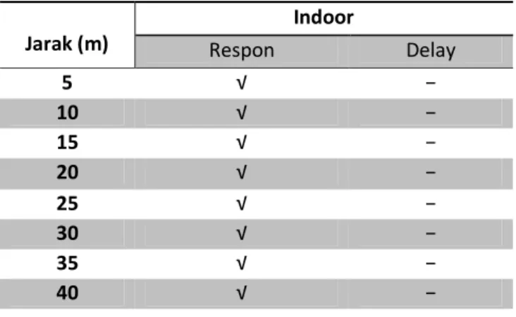
Tabel 4. Hasil Pengujian Response Indoor Jarak (m) Indoor Respon Delay 5 √ − 10 √ − 15 √ − 20 √ − 25 √ − 30 √ − 35 √ − 40 √ −
Dari hasil pengujian respon modul receiver di atas, modul masih dapat merespon sampai jarak 40 meter di ruangan tertutup. Ruangan tertutup yang digunakan adalah Hall lantai 3 Kampus Binus Syahdan. Modul bekerja dengan sangat baik tanpa terjadi delay. Hasil ini sesuai dengan kinerja XBEE yang memang dapat merespon hingga jarak 40 meter di ruangan tertutup.
Tabel 5. Hasil Pengujian Response Outdoor
Jarak (m) Outdoor Respon Delay 5 √ − 10 √ − 15 √ − 20 √ − 25 √ − 30 √ − 35 √ − 40 √ − 45 √ − 50 √ − 55 √ − 60 √ − 65 √ − 70 √ − 85 √ − 90 √ −
Dari hasil pengujian, modul di kondisi outdoor merespon sangat baik. Respon outdoor tidak bisa dilakukan lebih jauh lagi hingga modul tidak bisa merespon karena kendala sulit mencari tempat percobaan yang lebih besar lagi. Tetapi mengingat alat ini hanya dipakai di indoor maka hasil ini sudah lebih dari cukup karena didukung hasil respon indoor yang bagus.
Tabel 6. Hasil Pengujian Synchronization
Detik pada Shot Clock Detik pada Stopwatch Hasil
24 24 √ 23 23 √ 22 22 √ 21 21 √ 20 20 √ 19 19 √ 18 18 √ 17 17 √ 16 16 √ 15 15 √ 14 14 √ 13 13 √ 12 12 √ 11 11 √ 10 10 √ 9 9 √ 8 8 √ 7 7 √ 6 6 √ 5 5 √ 4 4 √ 3 3 √ 2 2 √ 1 1 √ 0 0 √
Dari hasil pengujian, detik pada shot clock sudah sama dengan detik pada jam digital. Ini penting untuk dicoba karena jika detiknya berbeda beberapa milisecond maka akan mengurangi ketepatan waktu permainan dan pemberian pelanggaran pada saat pertandingan basket berlangsung.
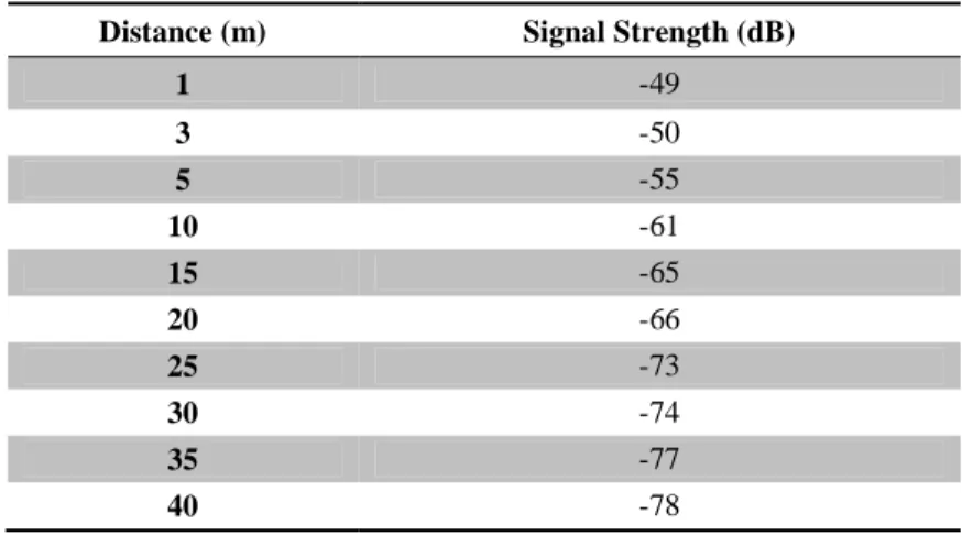
Tabel 7. Hasil Pengujian Kuat Sinyal Indoor
Distance (m) Signal Strength (dB)
1 -49 3 -50 5 -55 10 -61 15 -65 20 -66 25 -73 30 -74 35 -77 40 -78
45 -91
Dari hasil pengujian di atas, modul XBEE receiver dapat menerima sinyal dari transmitter hingga jarak 40 meter dengan daya pancar -78 dB. Pada jarak 45 meter modul XBEE receiver juga masih bisa menerima sinyal dari transmitter walaupun mulai banyak loss saat menerima data dengan daya pancar -91 dB.
SIMPULAN DAN SARAN
Kesimpulan yang didapat dari pengujian di atas adalah :1. Modul Receiver dapat merespon sampai dengan jarak 40 meter indoor tanpa delay dan mencapai 90 meter outdoor.
2. Daya pancar sinyal minimum XBEE receiver di indoor -91dB di jarak 45 meter.
3. Waktu yang dibutuhkan kedua XBEE untuk saling berkomunikasi setelah diaktifkan adalah 10 detik.
4. Hasil pengujian push button 0% error.
Saran yang dapat ditambahkan untuk pengembangan selanjutnya adalah :
1. Menempatkan display shot clock secara terpisah dari scoreboard dan menggunakan fitur point to multipoint dari XBEE.
2. Pengembangan pembuatan interface untuk menampilkan display di layar leptop yang tersinkronisasi dengan display scoreboard.
DAFTAR PUSTAKA
Chourasia, N. A., & Washimkar, S. P. (2012). ZIGBEE Based Wireless Air Pollution Monitoring.
International Conference on Computing and Control Engineering. Chennai: Coimbatore
Institute of Information Technology.
G, M., & A, P. (2011). Wireless Fetal Heartbeart Monitoring System using ZIGBEE and IEEE 802.15.4 Standard. Conference on Emerging Applications of Information Technology (pp. 83-86). KOLKATA: Dr. M.G.R. Educational & Research Institute University.
Hwang, S., & Yu, D. (2012). Remote Monitoring and Controlling System Based on ZIGBEE Networks.
International Journal of Software Engineering and Its Application .
Krishna, P. M., & Priya, K. P. (2012). Remote Wireless Health Care Monitoring System using ZIGBEE.
International Journal of Engineering Research & Technology .
Raut, R. A., & Malik, G. L. (2011). ZIGBEE Based Industrial Automation Profile for Power Monitoring Systems. International Journal on Computer Science and Engineering .
WIRELESS BASKETBALL SCOREBOARD
WITH XBEE 802.15.4
Anasthasia Giovanny
Computer Engineering, Bina Nusantara University, gio.anasthasia@gmail.com
Eva Ayuning Cahya
Computer Engineering, Bina Nusantara University, cahyaevaayuning@gmail.com
Robby Saleh
Computer Engineering, Bina Nusantara University, robby.saleh@gmail.com
ABSTRACT
Media cable is still widely used in the scoreboard system nowadays, although there are wireless system but the price is relatively expensive. The scoreboard that have been made is used to display points of the game of basketball. It is made semi automatic or require the operator to control. This scoreboard using XBEE as a wireless media communication and an Arduino Mega2560 as its control unit or microcontroller. This tool requires the push button as its input and a seven segment display. The scoreboard consists of display game as the viewer game display, display score as a score viewer for each team, display foul as a score foul viewer which is made by each team, display time as the time viewer of the game and display shot clock as the twenty four second countdown on basketball game. After doing experiment, the scoreboard works fine where the response of the transmitter and the receiver XBEE has been running well. Testing in response to 40 meters indoor and 90 meter outdoor.
Key Words : XBEE, Basketball scoreboard, Arduino Mega2560
PREFACE
Scoreboard is used in sport events as a result viewer of a match. Scoreboard in a basketball games is usually not only to show the score of the game , but also to display the game time, the number of quarters , shot clock , and the number of violations generated by the players in the match.
The scoreboards which are sold in Indonesia mostly still use the cable as a transmission media for inputting data to the viewer. Normally inputting media is in the form of a remote that uses cable connections to the viewer. The remote is held in accordance length with the cable that is not very practical. The remote holders were not feeling free to move because the remote was connected with a cable.
Based on that case the authors initiated to take advantage of the XBEE wireless technology to be more flexible when it is used. By using the XBEE, the remote does not need to use a cable anymore and will connect wirelessly and will reduce the cost as well. XBEE uses IEEE 802.15.4 networking protocol that works at a frequency of 2.4 GHz.
On 2012 in South Korea, XBEE was filed to support the home network controlling where XBEE is used as a remote to monitor and control the existing network systems at home (Hwang, Yu , 2012) .
In the health sector XBEE is also been used as a control and monitor tool to send someone’s physiological data to a PC which already installed the XBEE receiver and later it will be sent via SMS to medical person’s mobile phones. The signals which are sent by the XBEE transmitter provide heartbeat data and blood pressure of the person. So the officers could keep knowing their patients’ condition at any time without coming to the patients’ place (Krishna , Priya, 2012).
In India, XBEE technology is used as an air pollution control. Here, XBEE is used to send the data of air pollution every day in real-time to the data collector server, and will be shown on the internet (Chourasia, Washimkar, 2012).
The XBEE utilization for public facilities is also made by two engineers from Italy and Poland. They made LAN Intelligent street lighting system, with XBEE as a connector between one street light with the other street lights. Their systems are functioning XBEE as a connector cable instead of the street lights in general (Leccese, Leonowicz, 2009).
The XBEE role seems not stopping there. Filing XBEE as monitoring power usage in a factory also made in India. They are using the XBEE as a controller in turning on and off the electrical power at the factory engine without distance constraints; in other words, to control one engine plant will be monitored only by a PC that is connected to the XBEE transmitter and the machine has been installed XBee receiver (Raut, Malik, 2011).
So many engineers who use XBEE in all of life aspects and they encourage us to take advantage of the XBEE in the field of sports. In this study we will try to use the XBEE as a transmitter and a receiver on the scoreboard system. We will be using 2 XBEE modules that are XBEE transmitter and XBEE receiver. XBEE transmitter will be located at a remote to send data to XBEE receiver that will be put on the scoreboard.
To be able to run the XBEE transmitter and XBEE receiver in accordance with the instructions, the desired controller is needed; here we used two Arduino microcontrollers, and each microcontroller will be fitted with XBEE transmitter and receiver.
RESEARCH METHODS
The methods which are used by the author are the first to gather information and knowledge sources from the existing literatures and through the internet looking for information related to the Scoreboard. After that the author makes Scoreboard itself. The system consists of two modules that are the transmitter and receiver. A remote transmitter module which there were Arduino Mega2560 as a microcontroller and XBEE as the sender of the data. At the receiver module there are 15 seven segment displays that serves as a scoreboard. Generally, diagram block of the systems are as follows.
Figure 1. Diagram System Block
Diagram block above illustrates a built system which is divided into 3 sections, input, process and output. Where the input system is a wireless remote in which there is a XBEE transmitter and a microcontroller. When the transmitter sends data, the XBEE receiver connected to receiver microcontroller will receive and process the data according to the program that has been previously entered and produce output that is changing the order of the numbers on the scoreboard display. Microcontroller on the transmitter will wait for input from the push button that has been initialized in the program in the form of orders A to S in which the contents of the character commands located in the receiver microcontroller. Number of push button itself is representing the number of characters per command, while pressing the push button B the commands to increase the numbers game will be sent and in microcontroller, the receiver will be looked for firstly and after the order is sought and found then it processed, after that the numbers on the game display will increase by 1. Commands and characters that represent them can be seen in the table below.
Here is a flow chart of sending and receiving data which is done in accordance with entered XBEE commands:
Figure 2. Flow Process Diagram Transmit and Receive (Game)
Figure 2 is a flow diagram of sending and receiving data to add numbers in the game display and to repeat the numbers back to 0 by using reset.
Push Button Commands
on the Transmitter
The Meaning of Each Character’s Command on the Receiver
Game +1 B Add 1 point on the Game display
Game Reset C Return points to 0 on the Game display
Foul +1 D Add 1 point on the Foul display for team A
Foul Reset (A) E Return points to 0 on the Foul display for team A
Score +1 (A) F Add 1 score point for team A
Score +2 (A) G Add 2 score points for team A
Score +3 (A) H Add 3 score points for team A
Score Reset (A) I Return points to 0 on the Score display for team A
Shot Clock Stop A Return shot clock seconds to 24
Shot Clock Pause J Stop shot clock seconds temporary
Shot Clock Start/Reset
K If it is pressed for the one time, the time will start,
Twice, the time will be back to 24 and countdown
automatically
Score +1 (B) O Add 1 score point for team B
Score +2 (B) N Add 2 score points for team B
Score +3 (B) P Add 3 score points for team B
Foul +1 (B) L Add 1 point on the Foul display for team B
Foul Reset (B) M Return points to 0 on the Foul display for team B
Time Start/Pause R If it is pressed for the one time, the time will start,
Twice, the time will stop in last second at countdown
Figure 3. Flow Process Diagram Transmit and Receive (Foul)
Figure 3 is a flow diagram of sending and receiving data to add foul numbers in the display and to repeat the numbers back to 0 by using reset.
Figure 4. Flow Process Diagram Transmit and Receive (Score)
Figure 4 is a flow diagram of sending and receiving data to add numbers on the score display. There are four commands for each character that adds to the numbers 1, 2, and 3 and then repeat the last number to 0.
Figure 5. Flow Process Diagram Transmit and Receive (Shot Clock)
Figure 5 is a flow chart of sending and receiving data to set the shot clock display. There are three commands that represented each character that are stop, pause, start / reset.
Figure 6. Flow Process Diagram Transmit and Receive (Time)
Figure 6 is a flow chart of sending and receiving data to set the display time. There are two commands which each character is represented by the start / pause and stop.
The tests which are performed are a precision data test is to know whether the push button is functioning in accordance with their respective functions or not, suppression test two push buttons simultaneously, then the third is a response XBEE module test and final synchronization testing to determine whether the time of the shot on the scoreboard clock was synchronized with the seconds on the clock that already exists. Last is a signal strength test on the XBEE module to determine the farthest distance of XBEE to receive the signal.
RESULTS AND DISCUSSION
Table 2. Precision Data Testing ResultsButton Current Number on Scoreboard Final Number on
Scoreboard
Team A +1 Score 0 1
Team A +2 Score 1 3
Team A +3 Score 3 6
Team A Score Reset 6 0
Team A +1 Foul Reset 0 1
Reset Foul Team A 1 0
Team B +1 0 1
Team B +2 1 3
Team B +3 3 6
Team B Score Reset 6 0
Team B Foul Reset 1 0
Game Period +1 0 1
Game Period Reset 1 0
Shot Clock Start 0 24 countdown
Shot Clock Pause 24 countdown pause on current state
Shot Clock Stop pause's current state 24
Start Time 0 10 minutes countdown
Time Pause 10 minutes countdown pause on current state
Time Stop pause's current state 10 minutes
The result of the test is all push buttons work as the main functions. When the team A + 1 push button is pressed, on the display board the score will be automatically added by 1. Whether the team A + 2 score button is pressed the display score will be added by 2 and becomes 3, and so on. Until we reach the push button time test.
Table 3. Test Result of Simultaneously Pressed Push Button
Test Response Score B Foul B 1st √ − 2nd √ − 3rd − √ 4th √ − 5th √ − 6th − √ 7th − √ 8th √ − 9th √ − 10th − √
From the test, the result is that the Push Button can’t be simultaneously pressed. In the table you can see when the score B gave a response, at the same time Foul B did not show any reaction. Vice versa, when Foul B showed a response, Score B didn’t react.
Table 4. The Test of Indoor Response
Distance (m) Response Delay 5 √ − 10 √ − 15 √ − 20 √ − 25 √ − 30 √ − 35 √ − 40 √ −
From the receiver module response above, module still response until 40 meters indoor. The indoor which is used is Binus Syadan University’s hall on floor 3. The module works greatly without any delay. This results is compatible with XBEE performance which can response till 40 meters length indoor.
Table 5. Outdoor Response Testing Results
Distance (m) Outdoor Response Delay 5 √ − 10 √ − 15 √ − 20 √ − 25 √ − 30 √ − 35 √ − 40 √ − 45 √ − 50 √ − 55 √ − 60 √ − 65 √ − 70 √ − 85 √ − 90 √ −
From this test, the condition of the outdoor modules response finely. Outdoor response can not be extended again until the module is unable to respond because of the constraints is difficult to find a bigger
place to test again. But as we know this tool only used indoor so this result more than enough because supported by good indoor response.
Table 6. Synchronization Testing Results
Shot Clock (seconds) Stopwatch ( seconds) Results
24 24 √ 23 23 √ 22 22 √ 21 21 √ 20 20 √ 19 19 √ 18 18 √ 17 17 √ 16 16 √ 15 15 √ 14 14 √ 13 13 √ 12 12 √ 11 11 √ 10 10 √ 9 9 √ 8 8 √ 7 7 √ 6 6 √ 5 5 √ 4 4 √ 3 3 √ 2 2 √ 1 1 √ 0 0 √
From this test, calculations in seconds of Shot Clock is similar to the calculation in seconds of digital clock. This is important to be tried because if the calculation is different even some millisecond, it will educing the timeliness of the game and giving offense during a basketball game lasts.
Table 7. Indoor Signal Strength Results
Distance (m) Signal Strength (dB)
3 -50 5 -55 10 -61 15 -65 20 -66 25 -73 30 -74 35 -77 40 -78 45 -91
From the test above, XBEE receiver module can receive the signal from the transmitter till 40 meters length with emmitance of-78 dB. On 45 meters length XBEE receiver module still also could receive signals from the transmitter although a lot of loss when receive the data with emmitance of -91 dB.
CONCLUSION AND SUGGESTION
The conclusions from the test above :1. Receiver module can give the response till 40 meterslength indoor without any delay and reach 90 meters outdoor.
2. The minimum emmitance receiver signal XBEE in indoor -91 dB in 45 meters length. 3. Time is needed for both XBEE receiver in indoor -91 dB on 45 meters length. 4. The push button testing result is 0% error.
The suggestion which can be added for next development :
1. Place the shot clock display separately from the scoreboard and using point to multipoint feature from XBEE.
2. The development of interface to show the display on the laptop screen which is synchronize with scoreboard display.
REFERENCES
Chourasia, N. A., & Washimkar, S. P. (2012). ZIGBEE Based Wireless Air Pollution Monitoring.
International Conference on Computing and Control Engineering. Chennai: Coimbatore
Institute of Information Technology.
G, M., & A, P. (2011). Wireless Fetal Heartbeart Monitoring System using ZIGBEE and IEEE 802.15.4 Standard. Conference on Emerging Applications of Information Technology (pp. 83-86). KOLKATA: Dr. M.G.R. Educational & Research Institute University.
Hwang, S., & Yu, D. (2012). Remote Monitoring and Controlling System Based on ZIGBEE Networks.
Krishna, P. M., & Priya, K. P. (2012). Remote Wireless Health Care Monitoring System using ZIGBEE.
International Journal of Engineering Research & Technology .
Raut, R. A., & Malik, G. L. (2011). ZIGBEE Based Industrial Automation Profile for Power Monitoring Systems. International Journal on Computer Science and Engineering .