CAMERA CONSTANT IN THE CASE OF TWO MEDIA PHOTOGRAMMETRY
P. Agrafiotis and A. Georgopoulos
National Technical University of Athens, School of Rural and Surveying Engineering, Lab. of Photogrammetry Zografou Campus, Heroon Polytechniou 9, 15780, Zografou, Athens, Greece
(pagraf, drag)@central.ntua.gr
Commission V
KEY WORDS: Two media photogrammetry, Calibration, Camera constant, Refraction
ABSTRACT:
Refraction is the main cause of geometric distortions in the case of two media photogrammetry. However, this effect cannot be compensated and corrected by a suitable camera calibration procedure (Georgopoulos and Agrafiotis, 2012). In addition, according to the literature (Lavest et al. 2000), when the camera is underwater, the effective focal length is approximately equal to that in the air multiplied by the refractive index of water. This ratio depends on the composition of the water (salinity, temperature, etc.) and usually ranges from 1.10 to 1.34. It seems, that in two media photogrammetry, the 1.33 factor used for clean water in underwater cases does not apply and the most probable relation of the effective camera constant to the one in air is depending of the percentages of air and water within the total camera-to-object distance. This paper examines this relation in detail, verifies it and develops it through the application of calibration methods using different test fields. In addition the current methodologies for underwater and two-media calibration are mentioned and the problem of two-media calibration is described and analysed.
1. INTRODUCTION
Despite the growing interest of the photogrammetric community for the transmission of a beam of light through media of different density and hence different refractive index, refraction remains the main cause of geometric distortions in the case of multimedia photography. However, this effect cannot be compensated and corrected by a suitable camera calibration (Georgopoulos and Agrafiotis, 2012). This paper presents the relation of the effective camera constant of two-media to the one in air through the application of calibration methods using different test fields. In addition the current methodologies for underwater and two-media calibration are mentioned and the problem of two-media calibration is described and analysed.
In the work of Lavest et al. (2000), it is proved that when the camera is underwater, the effective focal length is approximately equal to that in the air when multiplied by the refractive index of water. This ratio depends on the composition of the water (salinity, temperature, etc.) and usually ranges from 1.10 to 1.34. It seems, that in two media photogrammetry, the 1.33 factor used for clean water in underwater cases does not apply and the most probable relation of the effective camera constant to the one in air is depending of the percentages of air and water in the total camera-to-object distance.
1.1 The Refraction Effect
Light rays passing through the flat interface of air and water will be refracted according to Snell’s law according to which the ratio of the sines of the angles of incidence and refraction is equal to the ratio of phase velocities in the two media, or equal to the reciprocal of the ratio of the indices of refraction: Consequently, the value of this ratio is dependent on the optical properties of the two media.
Two-media photogrammetry principles and geometry has been widely addressed in the literature (Tewinkel 1963, Shmutter and Monfigliolo, 1967, Masry, 1974, Karara, 1972, Slama,
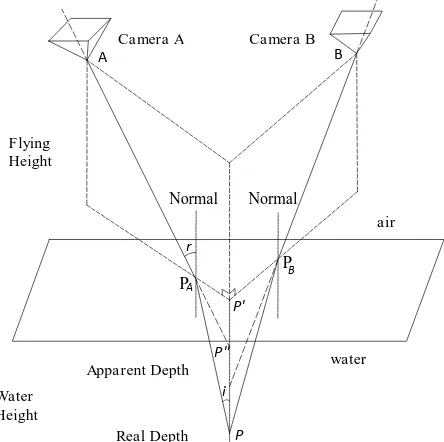
1980, Shan, 1994). According to the basic optical principles and equations, one may consider that accurate through-water photogrammetry is theoretically possible (Butler et al., 2002). The geometry of two-media photogrammetry has been addressed by Fryer and Kniest in 1985 and is presented in Figure 1. Important is that for simplicity and as with other studies, this research assumes that the water surface is planar.
Figure 1. The geometry of two-media Photogrammetry (Fryer and Kniest, 1985)
In Figure 1 it is observed that light rays derived from an underwater point P are refracted at the air/water interface (which is assumed planar) at PA and PB and captured by Camera A and Camera B respectively. If the systematic error resulting from the refraction effect is ignored, then the two lines APA and
A B
P P''
P' PA
PB
r
i
Camera A Camera B
Normal
Flying Height
Water Height
Real Depth
Apparent Depth water air
Normal
BPB do not intersect exactly on the normal, passing from the underwater point P, but approximately at P'', the apparent depth of the point. Thus, without some form of correction, refraction acts to produce an image of the surface which appears to lie at a shallower depth than the real surface, and it is worthy of attention that in each shot the Collinearity Condition is violated.
Light rays passing through the air/water interface are refracted according to Snell’s law:
Where i is the angle of incidence of a light ray originating from point P below the water surface, r is the angle of the refracted ray above the water surface, h is the actual water depth, hA is the apparent water depth and n is the refractive index, a value depended on the optical properties of two media (Fryer and Kniest, 1985).
1.2 Two Media Calibration: State of the Art
1.2.1 Underwater Camera Calibration: Underwater camera calibration is also considered as two media calibration since the camera is in a different medium from the calibration test field. However, this case is differentiated from the through water camera calibration by the amount of the percentages intervening between the camera lens and the test field. For the processing of underwater image data, two different approaches are reported. One is based on the geometric interpretation for light propagation through various media (e.g. air - housing device - water) and the other on the application of suitable corrections, in order to compensate for the refraction. Some researchers use a pinhole camera for the estimation of the refraction parameters (e.g.. Van der Zwaan et al., 2002; Pizarro et al., 2004; Singh et al., 2005), while others calibrate the cameras with the help of an object of known dimensions, which is placed underwater in situ (Gracias and Santos-Victor, 2000; Pessel et al., 2003; Höhle, 1971).
Self calibration is also applied for the camera-housing system, where it is assumed that refraction effects are compensated by the interior orientation parameters (Shortis and Harvey, 1998; Gründig et al., 1999; Canciani et al., 2003; Harvey et al., 2003; Drap et al., 2007; Shortis et al., 2007b). However, when analyzing the correction of the image points, especially for close ranges, the distance of the object points from the camera severely affects the correction (Telem and Filin, 2010). Hence it is concluded that a simple correction of the image points is not adequate.
Finally, in Lavest et al. (2000) it is proved that it is possible to infer the underwater calibration from the dry calibration by multiplying the dry parameters by 1,333, the water refractive index.
1.2.2 Through Water Calibration: It is characteristic of the problem that most applications related to two-media photogrammetry and specifically through water photogrammetry do not overcome the refraction effects by a camera calibration but try to correct them (Kotowski, 1988; Westaway et al., 2001; Butler et al., 2002; Ferreira et al.,2006; Murase et al., 2008; Mulsow, 2010; Georgopoulos and Agrafiotis, 2012).
1.3 The problem of a suitable camera calibration
Unlike underwater photogrammetric procedures, where according to the literature, the calibration is sufficient to correct the effects of refraction, in two media cases, the sea surface interface. Therefore, the common calibration procedure of the camera with a planar test field, fails to adequately describe the effects of refraction in the photos in such cases.
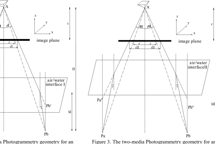
Figure 2. The two-media Photogrammetry geometry for an air/water interface I
Figure 3. The two-media Photogrammetry geometry for an air/water interface II, in a higher level than I.
r
In addition the shots from different angles and different distances alter the amount of water that covers the points of the test field, but also they significantly alter the angles of incidence of the light rays, thus leading to unreliable results.
Hence, taking images with incident angles deviating largely from the normal creates a sense of depth in the planar test filed while substantially increasing the angle of incidence of the optical beam. The result of this process is the overestimation of the effects of refraction at certain positions through the recording of an image of the test field that seems to lie at shallower depth than the actual (apparent elevation) and therefore it is imaged at a different scale. Consequently calibration techniques do not succeed, as they fail to provide a reliable result.
2. THEORETICAL APPROACH
In the photogrammetric and computer vision literature, the focal length is defined as the distance between the camera sensor and the optical center. It can be seen in Figure 2 and Figure 3 that rays coming from two points, Pa and Pb, situated at the same depth hI in Figure 2 and hII in Figure 3 and at the same distance H from a Camera station A are refracted at the air/water planar interface I and II and intersect the image plane at radial distances rI and rII respectively.
In the described setup and in dry conditions, the rays coming from these two points intersect the image plane at a radial distance r, smaller than rI and rII. According to two-media photogrammetry geometry and Snell's law, and taking into account that the focal length is constant, it is derived that if hII > hI, then rII > rI and always rII, rI > r. It is obvious that the increase of the water depth implies a decrease of the solid angle of view. This variation seems to be directly proportional to the camera constant because the sensor size (and hence the image size) is constant.
3. METHODOLOGY APPLIED
Relevant experiments were carried out in a simulation tank filled with clean water and varying depth. This well controlled experimental environment allowed the elimination of the errors caused by waves, turbid water and sun glint and increased the accuracy and reliability of the results. Finally, calibration results from real two-media conditions are also presented.
3.1 Proving the misleading results of a camera calibration in two media cases
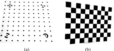
For proving the misleading results of a camera calibration in two media cases, three different calibration methods were carried out in air and water in order to achieve objective results. In addition, two different specially designed and made of plexiglass, test fields were used. More specifically the following camera calibration software suites or algorithms and test fields (Figure 4) were used:
i.A specially developed calibration sheet of Photomodeler® Scanner used for Photomodeler Calibration Suite (www.photomodeler.com), with full set of APs, and
ii.A specially developed calibration chessboard used for calibrating the camera with the FAUCCAL (Douskos et al., 2009.) and Camera Calibration Toolbox for Matlab® (Bouguet, 2004).
All necessary images were acquired with a Canon EOS MIII full frame DSLR camera with a resolution of 21Mpixel (5616x3744 pixels) and a 16 – 35 mm zoom lens, locked at 34mm, used for the experiment carried out in the simulation tank and locked at 16mm, for the calibration in the field conditions. While implementing the classical calibration methodology using planar test fields, it was decided to rotate the test fields and not move the camera around.
(a) (b)
Figure 4. Calibration boards for Photomodeler Scanner (a) and FAUCCAL and Camera Calibration Toolbox (CCT) (b)
To this direction, images of the planar test fields with ±45° roll angles were captured. This procedure is essential because in the case of 2D calibration fields images must have been acquired with significant tilts to produce strongly differing perspective views of the plane. For the proper implementation of this methodology, a special base was created in order to rotate the test field in the specified different angles and not the camera. In this way variations of the percentage of water and air in the calibration images and of the incident angle are avoided. This system primarily consists of a modified 3-way, pan/tilt photographic tripod head in order to allow the already described exact rotation of the mounted planar test fields. Also, the percentages of air and water intervening between camera and calibration fields were changed. It should be noted that camera calibration was also applied only in dry conditions using all the test fields in order to have a benchmark for the focal length and the other parameters of the Interior Orientation of the camera.
3.2 Retrieving the Camera Constant in the case of Two Media
Images of a specially graduated stable planar test field were taken with increasing water percentages, each time by 5%, maintaining the camera position and the test field constant in order to recover the effective camera constant by measuring and comparing the decreasing field of view. The images were also checked for lens distortions. This final and more effective procedure proves that in two media photogrammetry the effective camera constant ratio to the one in air is proportional to the percentages of air and water in the total camera-to-object distance.
4. EXPERIMENTAL RESULTS
4.1 Camera calibration in two media cases
As already described, camera calibration in two media cases using Photomodeler Calibration Suite, FAUCCAL and Camera Calibration Toolbox for Matlab® was applied in order to prove the resulting misleading results. The following presents these results. Table 1 and Figure 5 present the results from the camera calibration procedure with varying depths. It is obvious that the solutions are not stable. Moreover, it could be observed that as the percentage of the water intervening between the calibration The International Archives of the Photogrammetry, Remote Sensing and Spatial Information Sciences, Volume XL-5/W5, 2015
field and the camera is increasing, the computed camera constants differ from each other. This is the main problem caused by the refraction effect in the calibration process.
Water
Table 1. Camera constant results from experiments with 0, 15, 30, and 45% of intervening water between the camera and the
calibration field.
Figure 5. The computed camera constant according to the water percentages.
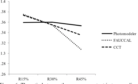
In Table 2, the results of a field calibration are presented and were not as expected. It is noted that the camera constant in that case is smaller than the one in air while it should be bigger. However, in Table 1 it is noticed that the resulting camera constants are greater than the one in air and the surprising fact is that their ratio is more than the refractive index of the water Table 2. Camera Calibration results in air and air-water in field
conditions (Georgopoulos and Agrafiotis, 2012)
Figure 6. The ratio between the camera constant in two-media and the one in air.
All the presented results prove the misleading results of a two-media camera calibration using planar test fields. As already stated, this is due to the fact that the amount of the refraction of a light beam is affected by the amount of the water that covers the point of origin and the angle of incidence of the beam in the interface air/water. This varies with the rotations of the planar test fields and leads to wrong results.
4.2 Camera Constant in the case of Two Media
As already mentioned, images of a specially graduated stable planar test field (Figure 7) were taken with increasing water percentages by 5%, while maintaining the camera - to - test field distance constant. In that way, the effective camera constant can be retrieved by measuring and comparing the decreasing field of view and accordingly the scale.
(a)
(b)
Figure 7. The graduated stable planar test field on 0% water (a) and 25% water (b)
Translating the described theoretical approach into mathematical terms, the camera constant coefficient is expressed by:
���� × ��� +���� � × ��� � (2)
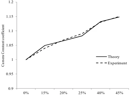
where, Pair and Pwater are the percentages of air and water respectively that intervene between camera and object, nair is the refractive index of the air equals to 1 and nwater the refractive index of the water. The resulting coefficient values for intervening water percentages up to 45% are presented in Figure 8 with the solid line. By the dashed line the experimental results from our applied methodology are represented. In more detail,
these results are derived by measuring the field of view of the camera, while the water percentage was increased. By measuring the field of view of an image containing water, the ratio of the field of view in dry conditions by the measured field of view was calculated.
Figure 8. Theoretical and Experimental coefficient comparison regarding to the intervening water percentages
Water Percentage Theoretical
Table 3. resulting coefficients regarding to the intervening water percentages up to 45%
By the reduction of the field of view, we are led to the increasing of the scale of the image, since the image dimensions are remaining the same. Since the camera - to - test field is remaining constant and by the well known Equation (3):
1
�=
� (3)
where k is the scale factor, H is the camera - to - test field distance and c is the camera constant, follows that the c increases as a function of k.
By observing the results presented in Table 3, it is noticed that if the decimal part of the theoretical coefficient derived for 25% water percentage is multiplied by four, the result is 1.33, which is the refractive index of the water.
5. CONCLUSIONS
It is apparent, that in two media photogrammetry, the 1.33 factor used for clean water in underwater cases does not apply and the relation of the effective camera constant to the one in air is depending on the percentages of air and water within the total camera-to-object distance. The effective camera constant to the one in air is given by:
�� − �� = ��� ×(����× ���+���� � × ��� �) (4)
where cair is the camera constant in air, Pair and Pwater are the percentages of air and water respectively that intervene between camera and object, nair is the refractive index of the air, which
equals to 1 and nwater the refractive index of the water. Moreover it was proven in this paper that the camera calibration in two-media photogrammetry leads to misleading results and thus the scientific community should not overcome the refraction effects by a camera calibration but they should try to correct those. The aforementioned mathematical relationship bridges the gap between the camera constant in air (dry) applications and the camera constant in underwater applications, as described by Lavest, Rives and Lapresté (Lavest et al., 2000).
ACKNOWLEDGEMENTS
The research leading to these results has been supported by European Union funds and National funds (GSRT) from Greece and EU under the project 3D ORO: Efficient and Effective 3D Computer Vision Tools for Improving the Performance of 3D Digitalization funded under the cooperation framework.
REFERENCES
Bouguet, J. Y. (2004). Camera calibration toolbox for matlab.
Butler, J.B., Lane, S.N., Chandler, J.H., Porfiri, E., (2002). Through-Water Close Range Digital Photogrammetry In Flume and Field Environment. Photogrammetric Record. 17(99) Q, pp. 419-439.
Canciani, M., Gambogi, P., Romano, F.G., Cannata, G., Drap, P., (2003). Low cost digital photogrammetry for underwater archaeological site survey and artifact insertion. The case study of Dolia wreck in secche della meloria-livorno-italia. International Archives of the Photogrammetry, Remote Sensing and Spatial Information Sciences, 34 (Part5/W12), pp. 95-100.
Douskos, V., Grammatikopoulos, L., Kalisperakis, I., Karras, G., and Petsa, E. (2009). FAUCCAL: An open source toolbox for fully automatic camera calibration. In XXII CIPA Symposium on Digital Documentation, Interpretation & Presentation of Cultural Heritage, Kyoto, Japan.
Drap, P., Seinturier, J., Scaradozzi, D., Gambogi, P., Long, L., Gauch, F., (2007). Photogrammetry for virtual exploration of underwater archeological sites. In: Proc. XXIth CIPA International Symposium, Athens, Greece, 1-6 October.
Elfick, M.H. and Fryer, J.G., (1983). Mapping in Shallow Water. University of Newcastle, Australia, Commission V, pp. 240-247.
Ferreira, R., Costeira, J.P., Silvestre, C., Sousa, I. and Santos, J.A., (2006). Using Stereo Image Reconstruction to Servey Scale Models of Rubble-Mound Structures. First International Conference on the Application of Physical Modelling to Port and Coastal Protection.
Fryer, J.G. and Kniest, H.K., (1985). Errors in Depth Determination Caused by Waves in Through-Water Photogrammetry. Photogrammetric Record, 11(66): pp. 745-753.
Georgopoulos, A., & Agrafiotis, P. (2012). Documentation of a submerged monument using improved two media techniques. In Virtual Systems and Multimedia (VSMM), 2012 18th International Conference on (pp. 173-180). IEEE.
Gracias, N., Santos-Victor, J., (2000). Underwater video mosaics as visual navigation maps. Computer Vision and Image Understanding 79 (1), pp. 66-91.
Gründig, L., Moncrieff, E., Schewe, H., (1999). The
design using computational structural modelling and large-scale underwater photogrammetry. In: Astudillo, R., Madrid, A. J. (Eds.), Proc. IASS 40th Anniversary Congress, 20-24 September, Madrid, Spain, IASS/CEDEX
Harvey, E.S., Cappo, M., Shortis, M.R., Robson, S., Buchanan, J., Speare, P., (2003). The accuracy and precision of underwater measurements of length and maximum body depth of southern bluefin tuna (Thunnus maccoyii) with a stereo-video camera system. Fisheries Research 63 (3), pp. 315-326.
Höhle, J., (1971). Reconstruction of the underwater object. Photogrammetric Engineering 37 (9), pp. 949-954.
Karara, H.M., (1972). Simple cameras for close-range applications. Photogrammetric Engineering, 38(5): pp. 447-451.
Kotowski, R. (1988). Phototriangulation in multi-media photogrammetry. International Archives of Photogrammetry and Remote Sensing, 27, B5.
Lavest, J. M., Rives, G., and Lapresté, J. T. (2000). Underwater camera calibration. In Computer Vision—ECCV 2000 (pp. 654-668). Springer Berlin Heidelberg.
Masry, S.E., (1974). Digital correlation principles. Photogrammetric Engineering, 40(3): pp. 303-308.
Mulsow, C. (2010). A flexible multi-media bundle approach. International archives of photogrammetry, remote sensing and spatial information sciences, 38(5), pp. 472-477.
Murase, T., Tanaka, M., Tani, T., Miyashita, Y., Ohkawa, N., Ishiguro, S., and Yamano, H. (2008). A photogrammetric correction procedure for light refraction effects at a two-medium boundary. Photogrammetric Engineering & Remote Sensing, 74(9), pp. 1129-1136.
Okamoto, A., (1982). Wave influences in two-media photogrammetry. Photogrammetric engineering and Remote Sensing, 48(9): pp. 1487-1499.
Pessel, N., Opderbecke, J., Aldon, M.J., (2003). Camera self-calibration in underwater environment. In: Proc. The 11-th International Conference in Central Europe on Computer Graphics, Visualization and Computer Vision, Plzen - Bory, Czech Republic, 3-7 February, pp. 104-110.
Pizarro, O., Eustice, R., Singh, H., (2004). Large area 3d reconstructions from underwater surveys. In: Proc. IEEE/MTS OCEANS Conference and Exhibition, 2, Kobe, Japan, 9-12 November, pp. 678-687.
Samper, D., Santolaria, J., Majarena, A. C., anf Aguilar, J. J. (2013). Correction of the Refraction Phenomenon in Photogrammetric Measurement Systems. Metrology and Measurement Systems, 20(4), pp. 601-612.
Shan, J. (1994). RELATIVE ORIENTATION FOR TWO-MEDIA PHOTOGRAMMETRY. The Photogrammetric Record, 14(84), pp. 993-999.
Shmutter, B, and Bonfiglioli, L, (1967). Orientation problems in two-medium photogrammetry. Photogrammetric Engineering, 33(12): pp. 1421-1428.
Shortis, M.R., Harvey, E.S., (1998). Design and calibration of an underwater stereovideo system for the monitoring of marine fauna populations. International Archives Photogrammetry and Remote Sensing, 32 (5), pp. 792-799.
Shortis, M.R., Seager, J.W., Williams, A., Barker, B.A., Sherlock, M., (2007b). A towed body stereo-video system for deep water benthic habitat surveys. In: Grün, A., Kahmen, H. (Eds.), Proc. Eighth Conference on Optical 3-D Measurement Techniques, ETH Zurich, Switzerland, 2, pp. 150-157.
Singh, H., Roman, C., Pizarro, O., Eustice, R., (2005). Advances in high resolution imaging from underwater vehicles. In: Proc. 12th International Symposium of Robotics Research, October 2005, pp. 430-448.
Slama, C.C. (Editor-in-Chief), (1980). Manual of Photogrammetry, Fourth edition, American Society of Photogrammetry, Falls Church, Virginia, 1056 pages.
Telem, G., Filin, S., (2010). Photogrammetric modeling of underwater environments. ISPRS Journal of Photogrammetry and Remote Sensing.
Tewinkel, G.C., (1963). Water depths from aerial photographs. Photogrammetric Engineering, 29(6): pp. 1037-1042.
Van der Zwaan, S., Bernardino, A., Santos-Victor, J., (2002). Visual station keeping for floating robots in unstructured environments. Robotics and Autonomous Systems 39 (3-4), pp. 145-155.
Westaway, R.M., Lane, S.N. and Hicks, D.M., (2001). Remote sensing of clear-water, shallow, gravel-bed rivers using digital photogrammetry. Photogrammetric Engineering & Remote Sensing, 67(11): pp. 1271-1281.