GEOMETRIC CALIBRATION OF THE CLEMENTINE UVVIS CAMERA USING
IMAGES ACQUIRED BY THE LUNAR RECONNAISSANCE ORBITER
E. J. Speyerer a,*, R. V. Wagner a, M. S. Robinson a a
School of Earth and Space Exploration, Arizona State University, Tempe, AZ – (espeyere, rvwagner, mrobinson)@asu.edu
Commission IV, WG IV/8
KEY WORDS: Moon, Geometric Calibration, Multi-Sensor Calibration, Camera Model, Optical Distortion
ABSTRACT:
The Clementine UVVIS camera returned over half a million images while in orbit around the Moon in 1994. Since the Clementine mission, our knowledge of lunar topography, gravity, and the location of features on the surface has vastly improved with the success of the Gravity Recovery and Interior Laboratory (GRAIL) mission and ongoing Lunar Reconnaissance Orbiter (LRO) mission. In particular, the Lunar Reconnaissance Orbiter Camera (LROC) has returned over a million images of the Moon since entering orbit in 2009. With the aid of improved ephemeris and on-orbit calibration, the LROC team created a series of precise and accurate global maps. With the updated reference frame, older lunar maps, such as those generated from Clementine UVVIS images, are misaligned making cross-mission analysis difficult. In this study, we use feature-based matching routines to refine and recalibrate the interior and exterior orientation parameters of the Clementine UVVIS camera. After applying these updates and rigorous orthorectification, we are able generate precise and accurate maps from UVVIS images to help support lunar science and future cross-mission investigations.
1. INTRODUCTION
1.1 Background
In 1994, the Clementine mission launched as part of a joint program between the Strategic Defense Initiative Organization and NASA (Nozette et al., 1994). Using images collected while in lunar orbit from the Ultraviolet/Visible (UVVIS) camera (Kordas et al., 1995; McEwen and Robinson, 1997), scientist generated a detailed global multispectral mosaic and a series of mineralogy and maturity maps (Edwards et al., 1996; Lucey et al., 1998; Robinson et al., 1999; Lucey et al., 2000a; Lucey et al., 2000b). To facilitate the mapping exercises, efforts were made to geodetically control the images into a global control network.
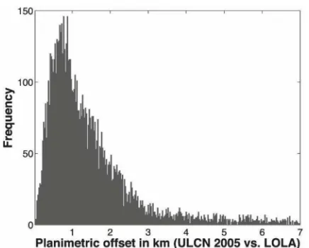
Specifically, in the late 1990’s the United States Geologic Survey (USGS) and the RAND Corporation used over 500,000 match points to systematically control 43,871 images used in the 750 nm global basemap (Davies et al., 1996; Edwards et al., 1996; McEwen and Robinson, 1997) to create the Clementine Lunar Control Network (CLCN). However, this analysis ignored topographic effects during the triangulation (i.e. assumed a spherical Moon with a radius of 1737.4 km) and later investigations showed the existence of large horizontal offsets (8-10 km) in the resulting maps due to extreme changes in the camera orientation parameters (Cook et al., 2002). Later work improved upon this initial control network, most recently the Unified Lunar Control Network (ULCN) 2005 produced by the USGS (Archinal et al., 2006). While the ULCN 2005 included the radius of the Moon during image triangulation, significant offsets (mean = 1.09 km; median = 1.59 km; Figure 1) still exist when compared to the current lunar reference frame. For this study, we are using images acquired by the Lunar Reconnaissance Orbiter (LRO) to update the Clementine UVVIS internal and external orientation parameters in order to create precise and accurate map products.
1.2 Clementine UVVIS Camera
The Clementine UVVIS camera was a framing camera capable of acquiring images in five different narrow bandpasses (415±20, 750±5, 900±10, 950±15, and 1000±15 nm) as well as a single broadband filter (400-1000 nm) using a filter wheel. The 5.6° × 4.2° field of view and 384 × 288 pixel CCD enabled the UVVIS camera to acquire images with a ground sampling distance of 115 m from an altitude of 425 km (although the point spread function of the optics reduces the true resolution). The UVVIS acquired global coverage of the Moon over two ~5 week mapping campaigns which the periselene was shifted from 28.5°S to 28.5°N to ensure image overlap in the equatorial region, i.e. 50°S to 50°N (McEwen and Robinson, 1997). While previous control networks have focused on a small subset of images (43,866 of nearly 560,750 images or less than 8%), we are controlling each image of illumined terrain. This will improve the alignment between UVVIS images the accurate and precise geodetic grid defined by LRO mission, thus enabling future cross-mission analysis.
1.3 Lunar Reconnaissance Orbiter Camera
The Lunar Reconnaissance Orbiter Camera (LROC) consists of three individual cameras: two Narrow Angle Cameras (NACs) and a single Wide Angle Camera (WAC). The LROC WAC is a push frame camera capable of providing images in seven different color bands: 321±32, 360±15, 415±36, 566±20, 604±20, 643±23, and 689±39 nm (Robinson et al., 2010). The WAC has a 90° field of view in monochrome mode and a 60° field of view in multispectral mode. From an altitude of 50 km, the WAC acquires images with a nadir pixel scale of 75 meters for the visible filters (384 meters for the UV filters). The WAC images almost the entire Moon each month, capturing the lunar surface under a variety of lighting conditions over time. This global dataset enables the creation of morphologic maps, near-global digital terrain models, and polar illumination movie sequences (Speyerer et al., 2011; Scholten et al., 2012; Speyerer and Robinson, 2013).
_______________________________ * Corresponding author
Once in orbit, the LROC team conducted a focused investigation to geometrically calibrate each of the three cameras using images and data collected while in orbit. Using a series of retro reflectors emplaced during Apollo and Luna missions to the surface (Wagner et al., 2016), a temperature based pointing model was derived for the twin Narrow Angle Cameras (Speyerer et al., 2014). A subset of NAC images were later used to calibrate the internal and external orientation parameters of the LROC WAC. With the improvement to the WAC orientation parameters, refined ephemeris derived with a new gravity model of the Moon (Mazarico et al., 2013; Lemoine et al., 2014), and a high-resolution topographic model (Scholten et al, 2012), WAC images can be orthorectified with an accuracy of 40 m without the use of ground control points (Speyerer et al., 2014). This enables the generation of regional multi-spectral maps with sub-pixel accuracy.
2. IMAGE REGISTRATION
2.1 Image Selection
In order to improve the observational geometry of each Clementine UVVIS image, we have developed a processing pipeline that provides statistics needed to refine the interior and exterior orientation parameters. First, for each Clementine UVVIS image, we will identify LROC WAC images acquired under similar lighting conditions (i.e. difference in sub-solar point between observations < 5°). In many cases, a single Clementine image may match three or more WAC observations due to significant overlap at higher latitudes and LRO’s extensive temporal coverage. In those cases, the UVVIS image will be registered to each WAC image separately. We estimate, based on image footprints published in the PDS, that we will register over 2.5 million UVVIS/WAC image pairs upon completing this project.
2.2 Image Preparation
Before registering the UVVIS/WAC pairs, each image is first radiometrically calibrated and a photometric correction is applied. In addition, information regarding the interior and exterior orientation parameters that is stored in a series of
image. For Clementine images, we follow the calibration procedures and photometric correction described in (Malaret et al., 1999; McEwen et al., 1998) while we follow the calibration procedures described in (Robinson et al., 2010) and use photometric function and parameters defined in (Sato et al., 2014) when processing LROC WAC images. These procedures are carried out using Integrated Software for Imagers and Spectrometers (ISIS) (Anderson et al., 2004), which is developed and maintained by the Astrogeology Research Program at the USGS.
2.3 Feature Matching
After the appropriate pre-processing steps are complete, the UVVIS/WAC image pairs are then registered using a series of control points. These control points are automatically derived using an ISIS utility called findfeatures that applies feature-based matching algorithms to detect similar features in each image (Figure 3). The software takes advantage of the OpenCV framework, which allows the user to select from a broad range of detectors, extractors, and matchers (Gracia et al., 2016). Findfeatures works directly with the level 1 UVVIS and WAC images in the ISIS cube format. Using the a priori SPICE information attached to each image, a fast geometric transform is applied to each image pair. This enables the application of virtually all OpenCV detectors and matches, including ones that are not scale and rotation invariant. The software also allows the user to specify more than one algorithm to apply during the matching process. The best matches will then be used to select the final control points and thus provide a robust and accurate output.
Findfeatures also incorporates a robust outlier detector to remove inaccurate tie points between the image pairs. This includes a bi-directional ratio test of the closest matches to each control point, symmetry test of bi-directional matches, epipolar constraints, and projective relationships using a homography matrix.
Using the latest LRO ephemeris provided by the Lunar Orbiter Laser Altimeter and Gravity Recovery and Interior Laboratory teams and the refined LROC camera model parameters, WAC images have a geodetic accuracy of better than 45 m (Speyerer et al., 2014). Therefore, the LROC WAC images can be directly used to tie the UVVIS images without the need to create large global control networks, such as the ones produced during the generation of the CLCN and ULCN 2005. This technical approach offers two major advantages over previous control attempts:
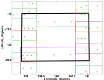
• Increased registration coverage: Previous Clementine UVVIS control networks relied on registering overlapping areas of images. As a result of the small sensor size (384 samples × 228 lines), very few pixels were available for registration. In addition, this meant that only the edges of the images were registered (Figure 2). With our approach described in this section, we are able to identify control points all across the UVVIS images since the selected WAC images cover the entire UVVIS field of view (Figure 3). This enables us to derive an accurate model of the exterior and interior orientation parameters for the Clementine spacecraft and UVVIS camera.
• Global control points: Previous control networks lack accurate control points on the lunar farside. The WAC images provide accurate locations for features globally, Figure 1- Histogram measuring the displacement of the
coordinates of named lunar features derived from the Clementine images (ULCN2005) to coordinates derived from LOLA hill shade images and a global LROC WAC mosaic (LRO reference frame)
in areas lacking control points. This will enable UVVIS images projected with the refined exterior and interior orientation parameters derived from this study to match directly to LROC images, maps derived from other LRO instruments (e.g. Diviner, LOLA, LEND, LAMP, mini-RF, etc.), as well as other datasets such as the Moon Mineralogy Mapper, which has been controlled to the same geodetic grid (Gaddis et al., 2016).
For each control point, we collect the latitude, longitude, and radius derived from the WAC image and the WAC/LOLA merged topography as well as the coordinates of the feature on the UVVIS CCD array (line and sample).
3. UVVIS CAMERA MODEL DEVELOPMENT
3.1 Interior Orientation
As part of effort to refine the LROC WAC camera model, the LROC team used statistics from registering more than 4,000 WAC images to 34,000 LROC NAC images acquired under similar lighting (note: previous on-orbit geometric calibration of
NAC images provided a geodetic accuracy of 18 m and thus an adequate ground truth for WAC calibration). These statistics were later used to identify a systematic timing offset in the camera, temperature dependent pointing variations, as well as calculate new radial distortion coefficients and a more accurate focal length (Speyerer et al., 2014).
Leveraging these techniques, we are collecting the image registration statistics from the feature matching routines described above (UVVIS line/sample coordinates and the latitude, longitude coordinates derived from the WAC image). To refine the UVVIS interior orientation parameters, we are first analyzing a subset of the entire collection of control points collected. By ignoring images that contain large offsets in the a priori ephemeris and spacecraft orientation parameters, we reduce the number of systematics offsets.
Once the control points are reduced, we will derive new interior orientation parameters for the UVVIS Camera, including:
• Calibrated focal length
• Optical boresight (line and sample) • Optical distortion
By analyzing global and orbit-to-orbit trends, we will be able to measure and correct additional timing offsets, temperature dependent pointing variations, and temperature and wavelength dependent internal orientation parameters as needed.
3.2 Exterior Orientation
After the new interior orientation parameters are derived, we will then use the entire network of control points to update the exterior orientation parameters for each UVVIS image. Previous studies (CLCN and ULCN 2005) have only updated the camera orientation and left the Clementine ephemeris untouched. Using the dense set of control points collected across the image, we will attempt to update both the ephemeris and camera orientation simultaneously. However, if we cannot pull out and differentiate between the two offsets, we will update only the camera orientation.
4. INITIAL RESULTS
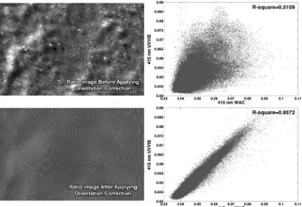
Figure 4 shows the results of using the approach defined above. In this example the Clementine UVVIS image was originally 1.8 km offset from the LROC WAC image. After applying the feature matching and refining the orientation parameters for the image, the offset was eliminated. The upper left image in Figure 4 is a ratio of the 415 nm bands from the UVVIS and WAC. Each image was map projected using the latest published SPICE kernels. The lower left image is a ratio of the same two map projected images, but after the Clementine UVVIS orientation parameters were corrected to address the offset between the UVVIS image and the WAC image in the LRO reference frame. The plots on the right show the corresponding joint-distribution for each case. Since the two images cover the same region, are similar wavelengths, are acquired under the same lighting environment, and have similar photometric corrections applied, the relationship should be linear with limited deviation.
5. ARCHIVING
The interior and exterior orientation refinements derived in this study will be incorporated into a series of new SPICE kernels: Figure 2- ULCN 2005 control points (green dots) overlaid
on UVVIS image footprints (colored polygons). The black, bold polygon represents the footprint for UVVIS image LUB1489H.249. Since the control network relied on image overlap, only a small number of points along the edges of the frames were used for registration.
Figure 3- Composite image of a WAC (red) and UVVIS image (cyan) overlaid using the a priori orientation parameters. The red circles (WAC) and green crosses (UVVIS) show the new control points derived from the feature matching routines (UVVIS: LUA2293F.102 and WAC: M123397685C).
Instrument Kernel (IK): contains the focal length, camera boresight, and optical distortion coefficients. The kernel will provide information to compute the boresight vector and the field of view geometry, which the current archived IK lacks. This new field of view definition will enable SPICE routines to derive image footprints (GETFOV), surface intercepts (SINCPT), and compute illumination angles (ILUMIN) using just the new SPICE kernels.
Frame Kernel (FK): includes the rotational offset measurements between the UVVIS reference frame and the reference frame of the spacecraft bus. If needed, the fixed offsets will be replaced with a pointer to a dynamic model stored in a C-matrix kernel similar to implementation of the LROC NAC and WAC.
C-Matrix Kernels (CK): defines the dynamic rotational offsets between reference frames. This includes the spacecraft orientation information in relation to the J2000 coordinate system and/or the dynamic orientation between components onboard the spacecraft bus.
Spacecraft Position Kernel (SPK): archives the ephemeris of the Clementine spacecraft over the entire mission in relation to the J2000 reference frame. The ephemeris will be updated for each instance in which a UVVIS image was acquired.
The new SPICE kernels will be delivered to Navigation and Ancillary Information Facility and incorporated into ISIS to enable users to map project individual UVVIS images using the refinements to the camera model and exterior orientation.
6. NEXT STEPS
After refining the internal and external orientation parameters, a new global multispectral map of the Moon will be produced using images from both the UVVIS camera and the WAC. The multi-spectral map will be comprised of the five narrow bandpasses from the UVVIS camera (415, 750, 900, 950, and 1000 nm) and the seven narrow bandpasses from the WAC (321, 360, 415, 566, 604, 643, and 689 nm). Since the LROC WAC has acquired over 60 global mosaics (from 1 January 2010 to 15 March 2016), images will be selected such that the lighting conditions are nearly identical to the Clementine images they overlap. All 12 bands will be photometrically normalized to common viewing and illumination angles (incidence = 30°, emission = 0°, and phase = 30°) using methods and photometric parameters defined by the UVVIS and WAC imaging teams (McEwen et al., 1997; Sato et al., 2014).
7. AWKNOLEGEMENTS
The authors would like to acknowledge support for this work from the Planetary Data Archiving, Restoration, and Tools (PDART) program under NASA grant NNX15AJ59G (PI: E. Speyerer) and the dedication of the LRO and GRAIL Science Teams that produce an invaluable dataset to enable precise and accurate mapping of the Moon.
Figure 4- Result of orientation correction. The left column is a set of ratio images derived from a pair of a map projected images (UVVIS: LUA2293F.102 and WAC: M123397685C) before (top) and after (bottom) applying the orientation correction. The right column is the corresponding joint-distribution to each case. The tighter cluster of points in the lower right plot indicate the improvement in the alignment between the two images.
8. REFERNECES
Acton, C.H., 1996. Ancillary data services of NASA’s Navigation and Ancillary Information Facility. Planet. Space Sci. 44, 65–70.
Anderson, J.A., Sides, S.C., Soltesz, D.L., Sucharski, T.L., Becker, K.J., 2004. Modernization of the Integrated Software for Imagers and Spectrometers. Lunar Planet. Inst. Sci. Conf. Abstr. 2039.
Archinal, B.A., M.R. Rosiek, R.L. Kirk, and B.L. Redding, 2006. The Unified Lunar Control Network 2005. U.S. Geological Survey Open-File Report 2006-1367, 12 p.
Cook, A.C., M.S. Robinson, B. Semenov, and T.R. Watters, 2002. Preliminary Analysis of the Absolute Cartographic Accuracy of the Clementine UVVIS Mosaics, Fall Meeting of the American Geophysical Union, Abstract no. P22D-09.
Davies, M., T. Colvin, K. Edwards, D. Cook, E. Lee, T. Becker, and A. McEwen, 1996. Modem lunar geodetic control, International Moon Workshop, Berlin.
Edwards, K.E., T.R. Colvin, T.L. Becker, D. Cook, M.E. Davies, T.C. Duxbury, E.M. Eliason, E.M. Lee, A.S. McEwen, H. Morgan, M.S. Robinson, T. Sorensen,1996. Global digital mapping of the Moon. Lunar Planet. Inst. Sci. Conf., Abstr. 1168.
Gaddis, L., Weller, L., Edmundson, K., Kirk, R., Archinal, B., Sides, S., Boardman, J., Malaret, E., Besse, S., 2016. Improved Geometric Control of Moon Mineralogy Mapper Data. Lunar Planet. Inst. Sci. Conf., Abstr. 1504.
Garcia, G., Suarez, O., Aranda, J., Tercero, J., Gracia, I., 2016. Learning Image Processing with OpenCV. Packt Publishing, pp. 232.
Kordas, J.F., Lewis, I.T., Priest, R.E., III, W.T.W., Nielsen, D.P., Park, H.-S., Wilson, B.A., Shannon, M.J., Ledebuhr, A.G., Pleasance, L.D., 1995. UV/visible camera for the Clementine mission, in: SPIE’s 1995 Symposium on OE/Aerospace Sensing and Dual Use Photonics. International Society for Optics and Photonics, pp. 175–186.
Lemoine, F.G., Goossens, S., Sabaka, T.J., Nicholas, J.B., Mazarico, E., Rowlands, D.D., Loomis, B.D., Chinn, D.S., Neumann, G.A., Smith, D.E., Zuber, M.T., 2014. GRGM900C: A degree-900 lunar gravity model from GRAIL primary and extended mission data. Geophys. Res. Lett. 41(10): 3382–3389.
Lucey, P.G., Blewett, D.T., Hawke, B.R., 1998. Mapping the FeO and TiO 2 content of the lunar surface with multispectral imagery. J. Geophys. Res. 103, 3679.
Lucey, P.G., Blewett, D.T., Jolliff, B.L., 2000a. Lunar iron and titanium abundance algorithms based on final processing of Clementine ultraviolet-visible images. J. Geophys. Res. 105, 20297.
Lucey, P.G., Blewett, D.T., Taylor, G.J., Hawke, B.R., 2000b. Imaging of lunar surface maturity. J. Geophys. Res. 105, 20377.
Malaret, E., L. Perez, H. Taylor, 1999. Clementine’s in-flight calibration results (UVVIS Camera), ACT’s Final Report to NASA (NASW-5014).
Mazarico, E., Goossens, S.J., Lemoine, F.G., Neumann, G.A., Torrence, M.H., Rowlands, D.D., Smith, D.E., Zuber, M.T., 2013. Improved Orbit Determination of Lunar Orbiters with Lunar Gravity Fields Obtained by the GRAIL Mission. LPI Contrib. 1719, 2414.
McEwen, A., Robinson, M., 1997. Mapping of the Moon by Clementine. Adv. Sp. Res. 19, 1523–1533.
McEwen,A., Eliason, E., Lucey, L., Malaret, E., Pieters, C., Robinson, M., Sucharski, T., 1998. Summary of radiometric calibration and photometric normalization steps for the Clementine UVVIS images. Lunar Planet. Inst. Sci. Conf. Corson, M.P., Resnick, J.H., Rollins, C.J., Davies, M.E., Lucey, P.G., Malaret, E., Massie, M.A., Pieters, C.M., Reisse, R.A., Simpson, R.A., Smith, D.E., Sorenson, T.C., Breugge, R.W., Zuber, M.T., 1994. The clementine mission to the moon: scientific overview. Science 266, 1835–9.
Robinson, M.S., A.S. McEwen, E. Eliason, E.M. Lee, E. Malaret, P.G. Lucey, 1999, Clementine UVVIS Global Mosaic: A New Tool for Understanding the Lunar Crust, Lunar Planet. Anderson, J., Tran, T.N., Eliason, E.M., McEwen, A.S., Turtle, E., Jolliff, B.L., Hiesinger, H., 2010. Lunar Reconnaissance Orbiter Camera (LROC) Instrument Overview. Space Sci. Rev. 150, 81–124.
Sato, H., Robinson, M.S., Hapke, B., Denevi, B.W., Boyd, A.K., 2014. Resolved Hapke parameter maps of the Moon. J. Geophys. Res. Planets n/a–n/a.
Scholten, F., Oberst, J., Matz, K.-D., Roatsch, T., Wählisch, M., Speyerer, E.J., Robinson, M.S., 2012. GLD100: The near-global lunar 100 m raster DTM from LROC WAC stereo image data. J. Geophys. Res. 117, E00H17.
Speyerer, E., Robinson, M.S., Denevi, B.W., 2011. Lunar Reconnaissance Orbiter Camera Global Morphological Map of the Moon, Lunar Planet. Inst. Sci. Conf. Abstr. 2387.
Speyerer, E.J., Robinson, M.S., 2013. Persistently illuminated regions at the lunar poles: Ideal sites for future exploration. Icarus 222, 122–136.
Speyerer, E.J., R.V.Wagner, M.S. Robinson, A. Licht, P.C. Thomas, K. Becker, J. Anderson, S.M. Brylow, D.C. Humm, M. Tschimmel, 2014. Pre-flight and On-orbit Geometric Calibration of the Lunar Reconnaissance Orbiter Camera, Space Science Reviews, in press.
Wagner, R., Nelson, D., Plescia, J., Robinson, M., Speyerer, E., Mazarico, E., 2016. Coordinates of Anthropogenic Features on the Moon, Icarus, in press.