39
Sensorless Vector Control of AC Induction Motor
Using Sliding-Mode Observer
Phuc Thinh Doan
#1, Tan Tien Nguyen
##2, Sang Kwun Jeong
*3, Sea June Oh
**4and Sang Bong Kim
#5#
Department of Mechanical & Automotive Eng., College of Eng., Pukyong National University Busan 608-739, Korea
5
Mechanical Engineering Faculty, Hochiminh City University of Technology, Viet Nam
*
Han Sung Well Tech Co, Ltd, Busan, Korea
**
Division of Marine System Engineering, Korea Maritime University, Busan 606-791, Korea
Abstract— This paper develops a sensorless vector controlled method for AC induction motor using sliding-mode observer. For developing the control algorithm, modeling of AC induction motor is presented. After that, a sliding mode observer is proposed to estimate the motor speed, the rotor flux, the angular position of the rotor flux and the motor torque from monitored stator voltages and currents. The use of the nonlinear sliding mode observer provides very good performance for both low and high speed motor operation. Furthermore, the proposed system is robust in motor losses and load variations. The convergence of the proposed observer is obtained using the Lyapunov theory. Hardware and software for simulation and experiment of the AC induction motor drive are introduced. The hardware consists of a 1.5kw AC induction motor connected in series with a torque sensor and a powder brake. A controller is developed based on DSP TMS320F28355. The simulation and experimental results illustrate that fast torque and speed response with small torque ripples can be achieved. The proposed control scheme is suitable to the application fields that require high performance of torque response such as electric vehicles.
[Keywords
—
Sliding-Mode Observer; AC Induction Motor; Sensorless Vector Control]I. INTRODUCTION
The Adjustable Speed Drives (ADS) are used in a wide variety of industrial applications such as pumps, fans, elevator, electrical vehicles, wind generation systems, etc. There are various types of electric motors in electric drives such as DC motors, AC motors, stepper motors. AC induction motors are the most popularly motor type used in industrial due to their simple construction, reliability, robustness and low cost.
Many attempts have been made to develop a sensorless vector control of AC induction motor. Several techniques have been proposed. Magnetic-Salience-Based methods are very promising for standstill and low-speed operation [1,2]. Their main disadvantage is the need for high precision voltage and current measurements. Also, these methods require a proper machine design. Model-Reference Adaptive System (MRAS) have a good performance over a large speed range [3,4]. Their disadvantage is the large influence of parameter deviation at low-speed and standstill operation. The extended Kalman filter has been used as the most appropriate solution for speed sensorless drives [5]. However, this stochastic observer has some inherent disadvantages, such as the influence of the noise characteristic, the computational burden and the absence of design and tuning criteria. The current harmonic spectral estimation method estimates the rotor speed from current harmonics [6]. This method have a very good performance at low speed, but needs a complicated hardware
and software setup for measuring and filtering the currents. Artificial intelligence methods [7] that use artificial intelligence techniques such as fuzzy logic and neural networks are robust to parameter deviation and measurement noise. However, they need long development times and an expertise in several artificial intelligence procedures.
This paper develops a sensorless vector controlled method for AC induction motor using sliding-mode observer. The proposed observer estimates the motor speed, the rotor flux, the angular position of the rotor flux and the motor torque in a robust and efficiency manner. For developing the control algorithm, modeling of AC induction motor is presented. Hardware and software for simulation and experiment of the AC induction motor drive are introduced. The simulation and experimental results illustrate that fast torque and speed response with small torque ripples can be achieved. The proposed control scheme is suitable to the application fields that require high performance of torque response such as electric vehicles.
II. MATHEMATICAL MODEL OF AN INDUCTION MOTOR
The motor model equation in the stator-fixed coordinate (ab coordinate) is as follows.
0
s
s s s
s s s
s
s s r s
r r r r r
s s s
s s s m r
s s s
r m s r r
d R
dt d
R j
dt
L L
L L
w
ì
= +
ï ï
ïï = + - =
í ï
ï = +
ï
= +
ïî
ψ
u i
ψ
u i ψ
ψ i i
ψ i i
(1)
where s s
u and s
r
u are stator and rotor voltage vectors; s
s
i
and s r
i are stator and rotor current vectors; s
s
ψ and s r
ψ are stator and rotor flux vectors; Ls and Lr are stator and rotor
winding self inductances; Lm is magnetizing inductance, Rs
and Rr are stator and rotor winding resistances and wr is the mechanical motor speed.
Depending on the viewpoint of the observer, the unmeasurable rotor current, s
r
i , and the stator flux, s
s
40
(
)
1
s s s
r r m s
r
L L
=
-i ψ i (2)
(
)
s s m s s
s s s r m s
r
L
L L
L
= +
-ψ i ψ i (3)
Now substituting s r
i and s
s
ψ into the voltage equations of Eq. (1) yields:
s s
s s s m r
s s s s
r
s
s s
m r r
r s r r
r r
d L d
R L
dt L dt
L R d
R j
L T dt
s w ì = + + ï ï í æ ö ï = - +ç - ÷ + ï è ø î i ψ u i ψ
0 i ψ
(4) With 2 2 1 m s r s r L R R L L g s æ ö = ç + ÷ è ø , m s r L L L k s
= , r
r
R
L
h = ,
(
)
2
1 Lm L Ls r
s = - , the following is obtained from Eq. (4).
(
)
(
)
1
s
s s s
s
s r r s
s
s
s s
r
m s r r
d j dt L d L j dt
g k h w
s
h h w
ì = - + - + ï ï í ï = - -ïî i
i ψ u
ψ
i ψ
(5)
After separating the real and imaginary components from Eq. (2), the followings are obtained.
1
1
s
s r r r s
s
s
s r r r s
s
r
r r r m s
r
r r r m s
di i u dt L di i u dt L d L i dt d L i dt a
a a b a
b
b a b b
a
a b a
b
b a b
g khy kw y
s
g kw y khy
s y
hy w y h
y
hy w y h
ì = - + + + ï ï ï = - - + + ï ï í ï = - - + ï ï ï = - + + ïî (6)
To get the complete model of the induction motor, the electromagnetic torque and the motor angular velocity are obtained as follows:
(
)
3 2
m
e s s s s
r
L p
T i i
L by a ay b
= - (7)
(
)
1
r
e L
d
p T T
dt J
w =
(8)
where Te, TL are electromagnetic torque and load torque, respectively; p is the number of pole pairs; J is inertial moment.
III. SLIDING MODE OBSERVER DESIGN
For sensorless control, it is necessary to make a simultaneous observation of the rotor flux and rotor speed. The proposed observer is compared with a conventional observer.
A. Conventional observer
The conventional observer is designed as follows.
The estimated stator flux is calculated based on the motor equations using a pure integrator as follows:
(
)
(
)
ˆ
ˆ
s s s s
s s s s
u i R dt
u i R dt
a a a
b b b
y y
=
-=
-ò
ò
(9)The estimated rotor flux is computed from estimated stator flux as follows:
2
2
ˆ ˆ
ˆ ˆ
s r m r
r s s
m m
s r m r
r s s
m m
L L L L
i
L L
L L L L
i
L L
a a a
b b b
y y y y æ - ö = -ç ÷ + è ø æ - ö = -ç ÷ + è ø (10)
The estimated angle of rotor flux is obtained as follows.
ˆ ˆ r r d dt q
w = where ˆ tan 1 ˆ
ˆ r r r b a y q y - æ ö = ç ÷
è ø (11)
B. Sliding-mode observer
First, the observer is given as follows [8]:
ˆ 1
ˆ ˆ ˆ ˆ ˆ
s
s s r r r s
s
di
i i u
dt L
a
a g a khy a kw y b a
s
¢
= = - + + + (12)
ˆ 1
ˆ ˆ ˆ ˆ ˆ
s
s s r r r s
s
di
i i u
dt L
b
b g b kw ya khy b b
s
¢
= = - - + + (13)
ˆ
ˆ ˆ ˆ ˆ
r
r r r r m s
d
L i dt
a
a a b a
y
y¢ hy w y h
= = - - + (14)
ˆ
ˆ ˆ ˆ ˆ
r
r r r r m s
d
L i dt
b
b b a b
y
y¢ hy w y h
= = - + + (15)
where iˆsa and iˆsb are the estimated stator current components,
ˆra
y and ˆyrb are the estimated rotor flux components and wˆr
is the estimated value of the mechanical motor speed. The followings are defined:
ˆ
s s s
ia =ia -ia, isb =iˆsb -isb, wr =wˆr-wr, ysa =yˆsa -ysa, ˆ
sb sb sb
y =y -y (16)
The definitions of Eq. (16) express the mismatch between estimated and real components. A new system can be developed as follows:
ˆ
s s r r r r r
i¢ = -a gia +khya +kw y b +kw y b (17)
ˆ
s s r r r r r
i¢ = -b gib -kw ya +khy b -kw ya (18) ˆ
ra ra r rb r rb
y¢ = -hy -w y -w y (19)
ˆ
rb rb r ra r ra
y¢ = -hy +w y +w y (20)
41
ˆ ˆ
ˆa s r s r
s =iby a -iay b
a s r s r
s =iby a -iay b (21)
b s r s r
s =ibya -iay b
The following positive Lyapunov function is defined.
(
2 2)
1
0
2 s s
V= ia +ib ³ (22)
Its derivative after substitution from Eq. (17) and (18) can be written as follows:
s s s s
V& =i i¢a a+i i¢b b
(
ˆ)
ˆ2 r a a r a b
V& = - gV-kw s -s -kw s +khs (23) The condition V&<0 can be written as follows:
(
)
2ˆ ˆ
r sa sa rsa V sb
g
w w h
k
- + > - + (24)
The following equation is selected as
( )
ˆr Ksgn sˆa
w = (25)
From Eq. (19), the following is satisfied V&<0:
ˆa r a r a
K s >w s + ³d ws +d (26)
where d 2gV hsb
k
= - +
If K is big enough with Eq. (26), the estimated current values, iˆsa and iˆsb , converge to the real values, isa,isb
(isa ®0, isb ®0, sˆa ®0).
According to sliding-mode theory, under the discontinuous control w =ˆr Ksgn
( )
sˆa , the equivalent motion can bedescribed by the set of equations sˆa =0, sˆa¢ =0 where sˆa¢
denotes derivatives of sˆa.
Using the conditions, isa =0, isb =0 , sˆa =0 , the condition sˆa¢ =0 becomes:
(
)
(
)
(
)
2 2
ˆ ˆ ˆ ˆ ˆ
ˆ
ˆ ˆ 0
a r r r r r r r
r r r r r
s b a a b a b
a a b b
kh y y y y kw y y
kw y y y y
¢ = - - +
+ - = (27)
From Eq. (22), the equivalent rotor speed is obtained.
(
)
(
)
(
)
(
)
2 2
2 2
ˆ ˆ
ˆ ˆ
ˆ ˆ
ˆ ˆ
ˆ ˆ
r r r r
eq
r r r
r r
r r r r
r r
a a b b
a b
b a a b
a b
y y y y
w w w
y y
y y y y
h
y y
-= =
+ -+
+
(28)
Substituting the equivalent speed value ˆeq r
w into Eqs. (19, 20), the following system of equations exist:
(
)
(
)
(
)
(
)
2
2 2
2
2 2
2
2 2
2
2 2
ˆ ˆ ˆ
ˆ ˆ
ˆ ˆ ˆ
ˆ ˆ
ˆ ˆ ˆ
ˆ ˆ
ˆ ˆ ˆ
ˆ ˆ
r r r r
r r
r r
r r r r
r
r r
r r r r
r r
r r
r r r r
r
r r
a a b
a a
a b
a a b
b
a b
b a b
b a
a b
b a b
b
a b
hy w y y
y y
y y
w y hy y
y
y y
w y hy y
y y
y y
hy w y y
y
y y
- +
¢ =
+
-
-+
+
-¢ =
+
-
-+
+
(29)
The roots of the characteristic polynomial of the above system are the following:
1 2 1
1 2 0 2 0
l l h l h
l l l
+ = - =
-ì ì
Û
í = í =
î î (30)
Therefore, under feedback w =ˆr Ksgn
( )
sˆa , the proposedobserver is forced to slide on sˆa =0 with equivalent value
ˆ ˆeq
r r
w =w , and the system of Eq. (26) is neutrally stable (y ¢ ®ra 0, yr¢ ®b 0, y =ra ca, yrb =cb where ca and cb
are constants). At steady state, Eqs. (19, 20) become:
ˆ
r r r
ca cb b
h w w y
- - = (31)
ˆ
rca cb r ra
w h w y
- - = - (32)
Because yˆra and ˆyrb are time-variant function, the only solution for the above system of equations is ca =cb =0 and
0
r
w = , which means that y =ra 0, yrb =0 and ˆ ˆ eq
r r
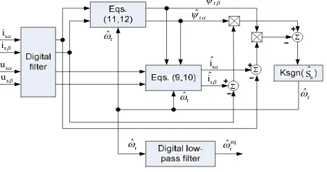
w =w . Fig. 1 shows the block diagram of the proposed observer.
å
å
å ˆ
a S s
ia
s ib
s ua
s ub
ˆs ia
ˆ s ib
ˆra y
ˆrb
y
ˆr
w
ˆr
w
ˆr
w
ˆr
w
ˆeq r
w
Fig. 1 Block diagram of the sliding mode observer
IV. SIMULATION AND EXPERIMENTAL RESULTS
The proposed sliding mode observer has been tested in order to verify its behaviour and robustness using testing system as shown in Fig. 2. The testing system consists of an AC induction motor (1.5kw), a torque sensor, a powder brake.
42
Fig. 2 Testing system in experiment
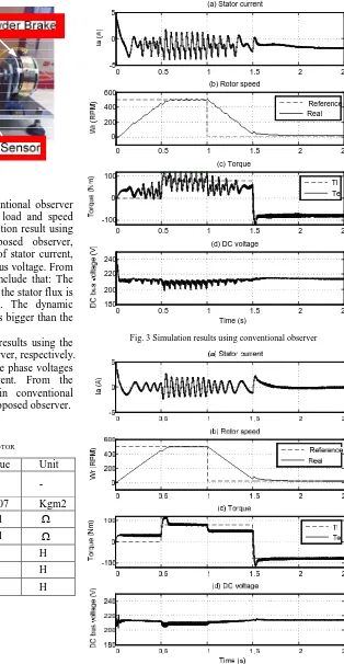
Simulation has been done with the conventional observer and the proposed observer in condition of load and speed variations. Fig. 3 and Fig. 4 show the simulation result using the conventional observer and the proposed observer, respectively. The simulation results consist of stator current, rotor speed, electromagnetic torque and DC bus voltage. From the results in Fig. 3 and Fig. 4, we can conclude that: The implementation of pure integrator to estimate the stator flux is difficult because of initial value problem. The dynamic performance is lower and torque oscillation is bigger than the proposed observer.
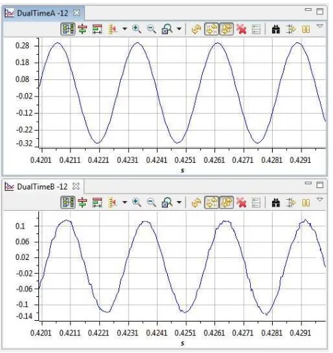
Fig. 5 and Fig. 6 show the experimental results using the conventional observer and the proposed observer, respectively. In experimental results, the upper pictures are phase voltages and the lower pictures are phase current. From the experimental results, the phase current in conventional observer has a larger ripple than the one in proposed observer.
TABLEI
PARAMETER'S VALUES OF INDUCTION MOTOR
Symbol Description Value Unit
p Number of pole
pairs 2 -
J Inertial moment 0.007 Kgm2
s
R Stator resistance 0.01 W
r
R Rotor resistance 0.01 W
r
L Rotor inductance 3.1 H
s
L Stator inductance 3.1 H
m
L Mutual inductance 3 H
0 0.5 1 1.5 2 2.5
-5 0 5
(a) Stator current
0 0.5 1 1.5 2 2.5
0 200 400 600
(b) Rotor speed
Reference Real
0 0.5 1 1.5 2 2.5
-100 0 100
(c) Torque
Tl Te
0 0.5 1 1.5 2 2.5
180 200 220 240
(d) DC voltage
Time (s)
Fig. 3 Simulation results using conventional observer
43
Fig. 5 Phase voltage and phase current using conventional observer in experiment
Fig. 6 Phase voltage and phase current using sliding-mode observer in experiment
V.CONCLUSIONS
This paper developed a sliding-mode observer for sensorless vector control of AC induction motor. The modeling was also presented. Hardware for the simulation and experiment is described. The proposed observer was compared with the conventional observer. The simulation and experimental results showed that the proposed observer has smaller torque ripple than the conventional observer. The proposed observer was robust in high speed and low speed operation and load variation.
ACKNOWLEDGEMENT
This research was supported by a grant from Construction Technology Innovation Program (CTIP) funded by Ministry of Land, Transportation and Maritime Affairs (MLTM) of Korean government.
REFERENCES
[1] M. Schroedl, “Sensorless control of AC machines at low speed and standstill based on the INFORM method,” Proc. IEEE-IAS Annual meeting (1996), pp. 270-277.
[2] P.L. Jansen, R.D. Lorentz, “Transducer-less position and velocity estimation in induction and salient AC machines,” IEEE Trans. Ind. Appl. , vol. 31, pp 240-247, Mar. 1995.
[3] C. Schauder, “Adaptive Speed Identification for Vector Control without Rotational Transducers,” IEEE Trans. Ind. Appl. Vol.28, pp.1054-1061, Sep. 1992.
[4] J. Maes, J.A. Melkebeek, “Speed Sensorless Direct Torque Control of Induction Motors Using an Adaptive Flux Observer,” IEEE Trans. Ind. Appl. Vol. 38, pp. 778-785, May 2000.
[5] R. Kim, S.K. Sul, M.H. Park, “Speed Sensorless Vector Control of Induction Motor using extended Kalman Filter,” IEEE Trans. Ind. Appl.
Vol. 30, pp. 1225-1233, Sep. 1994.
[6] K.D Hurst, T.G. Habetler, “Sensorless Speed Measurement Using Current Harmonic Spectral Estimation in Induction Machines Drives,” IEEE Trans. Power Electronics, vol. 11, pp.66-73, Jan. 1996.
[7] P. Vas, Artificial-Intelligence-Based Electrical Machines and Drives Application of Fuzzy, Neural, Fuzzy-Neural and Genertic-Algorithm Based Techniques, Oxford Univ. Press, UK, 1999.