ANALYZING THE BOUNCE AND PITCH
PHENOMENON OF VEHICLE MODEL THROUGH
XZBM ALGORITHM
Djoko W. Karmiadji
Mechanical Engineering Department, Pancasila University Srengseng Sawah – Jagakarsah, Jakarta Selatan 12640, Indonesia
E-mail: [email protected]
ABSTRACT
In general, a vehicle model is one having multiple bodies, with each body being supported on a suspension represented by the tires, springs, and damping devices. The components of rigid body motion contain displacements, velocities, and accelerations at the body center of mass. These components consist of translation and rotation in and about the orthogonal axis directions. Since the springs and dampers have the steady loading due to the sprung body, the steady state of the model can be determined. The vertical bounce and pitch responds are influenced by the stiffness of dampers, springs and tires. The pure bounce is represented by the vertical response and the pitch motion is represented by the rotation at its rotation center. This paper demonstrates the bounce and pitch phenomenon through the benchmark model of vehicle, which is analyzed for determining the equilibrium state. The equations for bounce and pitch plane motions representing the X-Z multibody system are established by using the XZBM algorithm. The vehicle parameters are used for the numerical computations which the analysis established the bounce and pitch conditions.
Key-Words: tires, springs, damping, bounce, pitch, steady, X-Z multibody system, XZBM algorithm
INTRODUCTION
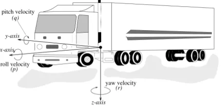
orthogonal system expressing the standard coordinate system [1] of a vehicle is shown in Figure 1., where the orthogonal axes are defined as
x-direction : positive forward.
y-direction : positive right.
z-direction : positive down.
These axis directions follow the right hand rule as seen by the driver. The orientation of the vehicle axis system x, y, z with respect to the fixed global reference axis system X, Y, Z can be described by a sequence of Euler angular rotations.
Vehicle velocity, therefore, is equal to the vector quantity expressing the velocity of a point in the sprung mass using the x, y, z axis system, relative to the fixed system. There are six velocity components [1]:
Figure 1. The orthogonal axis system.
1. Forward velocity is the component of the vector velocity perpendicular to the y-axis and parallel to the road plane (x).
2. Lateral velocity is the component of the vector velocity perpendicular to the x-axis and parallel to the road plane (y).
3. Bounce velocity is the component of the vector velocity perpendicular to the road plane and parallel to z-axis (z).
4. Roll velocity (p or ) is the angular velocity about the x-axis.
5. Pitch velocity (q or ) is the angular velocity about the y-axis. 6. Yaw velocity (r or ) is the angular velocity about the z-axis.
Basic Motion Equation
In accordance with Euler's method, the orientation of a moved body axis system (x, y, z) with respect to a fixed axis system (X, Y, Z) is given by a sequence of three angular rotations. The sequence of rotations is started from a condition in which the two sets of axes are initially aligned [1] and defined to be:
A yaw rotation, , about the aligned z and Z-axis.
A pitch rotation, , about y-axis.
A roll rotation, , about x-axis.
A rotational transformation matrix, in which a moved body system {B} rotates relative to the fixed reference frame {A}, is developed and is designated as the Z-Y-X rotation using the Euler angle convention [2]. The final orientation of
These rotational matrices result in non-linear equations if the sine and cosine terms are retained. Often simplifying assumptions are made. For instance, a vehicle motion will pitch excessively; hence, the terms sin, sin, cos, and cos are usually replaced by , , 1, 1, respectively, by use of small angle theory. This has a consequent simplification of the system relations [3].
The equations of motion can be determined by using a Lagrangian approach, which derives a differential equation in terms of kinetic, potential, and dissipative energies of the system. The algorithm for obtaining the equations of motion for a single-body system can be easily demonstrated by a set of spring-damping systems placed between a moving body i and a fixed body. The rotational transformation matrices, obtained using Euler's angle method, along with the coordinate systems of the model are developed and used to verify the kinetic and potential energies, and also the dissipative functions.
The Lagrangian approach to the formulation of the equations of motion can also alleviate some of the difficulties found in the direct application of Newton's laws of motion to complex systems. Lagrange's equation [3,4] may be written as
X - Z Body Motion Equation
The longitudinal distance between the axles generates a multi-input system that responds with pitch motions as well as vertical bounce. The pitch motions are generally considered as the primary source of longitudinal vibrations at locations around the center of gravity. The combination of pitch and bounce motions will determine the vertical and longitudinal vibrations at any point in the vehicle [5].
The vertical vibration response of the vehicle due to rigid-body motions will vary along the length of the vehicle, depending on the relative actions of the bounce and pitch motions. Near the center of rotation of the vehicle in the x - z plane, the vertical vibrations are affected only by bounce motion. On most vehicles there is a coupling of motions in the vertical and pitch directions, such that there is no pure bounce or pitch modes. The analytical study treats the system as a rigid body supported by suspensions consisting of springs and dampers as shown in Figure 2. Using Figure 2, the algorithm for the x-z plane can be developed by x - z body motion (XZBM) algorithm [6].
Figure 2. X-Z vehicle model.
By using the parameters in Figure 2 and XZBM algorithm, the kinetic energy can be expressed as the following equations.
-The dissipative function is
This system has three independent variables, therefore the motion equations are
ANALYSIS AND DISCUSSION
The benchmark model of the Bombardier Iltis vehicle [7] is analyzed for determining the equilibrium state. Referring to the definitions of Figure 2, Frik, et al. [7] quantified the Bombardier Iltis vehicle.
ms = 630.0 kg I' = 810.0 kg m
2
tf = 0.94 m tr = -1.047 m
Kvf = 24529.0 N/m Kvr = 36975.0 N/m
Cf = 9945.627 N s/m Cr = 9945.627 N s/m
kvf = 41641.0 N/m kvr = 40162.0 N/m
Ro = 0.214 m
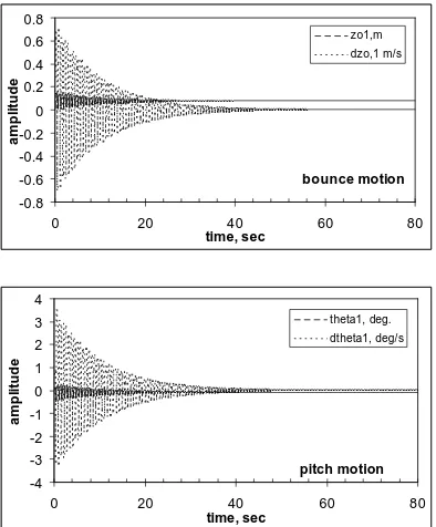
The stiffness coefficients for the dampers, springs and tires are the results of static equilibrium tests performed by Frik, et al. [7]. The test assumed that the tires produced no longitudinal or lateral forces in the equilibrium condition. However, the magnitudes of bounce and pitch displacements have not been determined. This implementation computes the equilibrium state and is represented by the bounce and pitch motion shown in Figure 3. The figure shows that steady state is reached after approximately 60 seconds. The vertical displacement, zo1, is 0.0756 m
and the rotation, 1, equals to -0.0863 degrees
bounce motion -0.8
-0.6 -0.4 -0.2 0 0.2 0.4 0.6 0.8
0 20 40 60 80
time, sec
a
m
p
li
tu
de
zo1,m dzo,1 m/s
pitch motion -4
-3 -2 -1 0 1 2 3 4
0 20 40 60 80
time, sec
a
m
p
li
tud
e
theta1, deg. dtheta1, deg/s
An input disturbance can be given to the tires through ff(t) and fr(t) during
the steady state. This is assumed that the vehicle runs at steady speed and there is a disturbance on the road which is first hit by the front tire and followed by the rear tire. The disturbance is given as a function of time and a sine wave defined as ff(t)
= 0.1 sin (xt) for 0.05 < t < 0.25 second and fr(t) = 0.1 \sin (xt) for 0.25 < t < 0.45
second as shown in Figure 4.
ff(t)=fr(t)=0.1 sin(xt), dx = 10 m/s
-0.15 -0.1 -0.05 0 0.05 0.1 0.15
0 0.1 0.2 0.3 0.4 0.5
time , se c.
a
m
p
li
tu
d
e
,
m
.
ff(t) fr(t)
Figure 4. A given disturbance as input parameters of ff(t) and fr(t).
bounce motion -0.4
-0.3 -0.2 -0.1 0 0.1 0.2 0.3 0.4
0 5 10 15 20
time, sec
a
m
p
li
tu
d
e
zo1, m dzo1, m/s
pitch motion -10
-8 -6 -4 -2 0 2 4 6 8 10
0 5 10 15 20
time, sec
a
m
p
li
tu
d
e
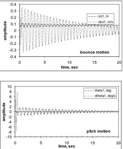
Figure 5 is an output in which the disturbance is shown in the "input" graph (figure 4) and the responses are expressed in the "bounce motion" and "pitch motion" graphs. The reaction of pitch motion is very significant during the disturbance, but sharply decreases after the disturbance ends, or t 0.45 second. The bounce motion sharply increases during the disturbance and smoothly decreases after this disturbance.
Further analyses can be performed as well on the problem given by varying the disturbances depending upon the condition of the road. The simulation should consider the vehicle speed and the distance between the front and rear tires.
CONCLUSION
The equations for bounce and pitch plane motions representing the X-Z multibody system were established by using the XZBM algorithm. The parameters of Bombardier Iltis vehicle [7] are used for the numerical computations which the analysis established the bounce and pitch conditions.
The algorithms are implemented into the protocols for symbolically deriving the motion equations which are valid to the same equations derived the other researchers. Besides the motion equations, the Fortran subroutines along with IMSL library computed the numerical analysis. The results of algorithm implementation have no contradiction with the study performed by the previous researchers.
With the simulation method that has been done above, there needs to be done similar simulations with the vehicle’s input parameters adjusted in accordance with the condition or types of the vehicle, which is often used on highways. For example, the simulations are performed by using suspensions with different suspension characteristics, different load and different dimension. This is needed to know how far are the critical bounce and pitch vehicle performances from empty to full load during its operation in the highways.
REFERENCES
SAE Handbook, Volume 4, On-Highway Vehicles and Off-Highway Machinery, Vehicle Dynamics Terminology - SAE J670e, Society of Automotive Engineers, Inc, 1993, pp 34.250-34.259.
Craig, John J., Introduction to Robotics Mechanics and Control, Addison-Wesley Publishing Company, Inc., second edition, 1989.
Ellis, J.R., Vehicle Dynamics. Business Books Limited, London, First published 1969.
Greenwood, D.T., Principles of Dynamics, Prentice-Hall, Inc., Englewood Cliff, New Jersey, second edition, 1988.
Karmiadji, D.W., Interaction Between The Tractor and Trailer as a Multibody System. Ph.D. Dissertation, The University of Alabama, 1997.
![Figure 2. Using Figure 2, the algorithm for the x-z plane can be developed by x - z body motion (XZBM) algorithm [6]](https://thumb-ap.123doks.com/thumbv2/123dok/1339278.795741/4.499.142.355.302.451/figure-using-figure-algorithm-plane-developed-motion-algorithm.webp)