Sanka Nirodha Perera *, Hetti Arachchige Nalani, Hans-Gerd Maas
Institute of Photogrammetry and Remote Sensing, Technische Universität Dresden, Helmholtz Straße 10, 01069
Dresden, Germany - [email protected], [email protected]
Commission III, WG IV
KEY WORDS: Airborne Laser Scanning, planar faces, adjacency relationship, roof topology graph, shortest closed cycles
ABSTRACT:
In this paper, an automatic approach for the generation and regularization of 3D roof boundaries in Airborne Laser scanner data is presented. The workflow is commenced by segmentation of the point clouds. A classification step and a rule based roof extraction step are followed the planar segmentation. Refinement on roof extraction is performed in order to minimize the effect due to urban vegetation. Boundary points of the connected roof planes are extracted and fitted series of straight line segments. Each line is then regularized with respect to the dominant building orientation. We introduce the usage of cycle graphs for the best use of topological information. Ridge-lines and step-edges are basically extracted to recognise correct topological relationships among the roof faces. Inner roof corners are geometrically fitted based on the closed cycle graphs. Outer boundary is reconstructed using the same concept but with the outer most cycle graph. In here, union of the sub cycles is taken. Intermediate line segments (outer bounds) are intersected to reconstruct the roof eave lines. Two test areas with two different point densities are tested with the developed approach. Performance analysis of the test results is provided to demonstrate the applicability of the method.
1.1
1.2
* Corresponding author
1. INTRODUCTION Motivation & Goals
With the development of sensor technology, Airborne Laser Scanner (ALS) demonstrates the high potential for the acquisition of accurate three dimensional dense point clouds in a rapid manner. Consequently, point clouds are often employed for the reconstruction of complex 3D building models. It has been shown that not only precise planar faces and accurate plane intersection lines, but also approximate building outlines can be reconstructed from the ALS data (Maas and Vosselman, 1999; Vosselman, 1999; Schwalbe et al., 2005). Moreover, step-edges can also be weakly defined. Although approximate roof edges should be regularised in order to improve the building shapes, building models can easily be reconstructed from the point clouds itself (Rottensteiner and Briese, 2003). The existing methods in automatic building modelling can be categorized into 2 groups namely data driven & model driven approaches. Due to the difficulty of defining sufficient number of model primitives, most authors still interest to work with the data driven concepts. However, missing data is the major drawback in this aspect (Ouder Elberink, 2010). Image data or building ground plans can be intergraded to avoid effect due to missing data of the point clouds (Khoshelham, 2005). If no such additional data are used, then modelling algorithms have to rely on sparely distributed point clouds itself. In this reconstruction workflow, automatic roof plane extraction and 3D roof modelling are the most crucial steps. Furthermore, recognition of correct topology, information like ridge-lines, semantics and proper constraints (geometric) are important since it enhances the completeness and correctness of the 3D building models (Ouder Elberink, 2010). Concerning above facts, in this paper, we focus above two steps and present an automatic 3D roof
reconstruction approach based on the data driven concepts. The proposed methodology mainly relies on the adjacency relationship of planar segments. We introduce (closed) cycle graph concept, especially, for the manipulation of the roof topology and feature-lines.
Initially, raw points cloud is segmented into planar faces and classified as terrain and off-terrain segments. Valid roof planes are extracted afterwards. A shape based urban vegetation recognition method is proposed in order to minimize the effect due to closed vegetation on subsequent roof modelling. Roof modelling is then performed based on the cycle graph approach with some geometric constraints. We fit roof corners, by extracting the information from the data, in a valid manner based on the closed cycles. The selection of proper corner features to be intersected and the nature of the convergence are given by the closed cycle.
The data used for the validation of the algorithms was captured by a Leica ALS50 over the city of Vaihingen, Germany. The dataset is being used by the authors as part of the ISPRS Test Project on Urban Classification and 3D Building Reconstruction in 2012 (ISPPS Commission III, 2011).
Related work
method. In this method, it is assumed that the building has a main orientation so that 3D polyhedral models are reconstructed through the generalization of weakly defined building edges. Rottensteiner and Briese (2003) describe problems related to the intersection line and step-edges, between two segments and how geometric constraints can be added on such features. Later, the work is extended and obtained a more reliable result in (Rottensteiner et al. 2005). Another method, based on planar segments, is devised by Dorninger and Pfeifer (2008) and mentioned that the segmentation is one of the most crucial steps for obtaining a reliable model. According to the method, segment borders are approximated by α-shapes and the deviations of the fitted outlines are regularized by forcing directional constraints to the outline directions. Schwalbe et al. (2005) propose another kind of reconstruction approach based on the specific orthogonal point projection strategy.
(Verma et al., 2006) assume that a complex building can be constructed by combining several primitive shapes and introduced the graph matching concept for building reconstruction. They decompose a complex roof into many predefined simple shapes through the recognition of roof adjacency by sub-graph matching. Ambiguity of the graph matching with data features is avoided by matching the sub-graphs in a decreasing order of their complexity. However, the approach was limited to a few primitive shapes. Later, formal grammar is applied on top of the primitive shapes which have been identified by the sub graph matching by Milde et al. (2008). In addition to the grammar rules, some additional corner connectors have also been used to get a valid roof model. The most recent contribution for building reconstruction based on roof topology is given by Oude Elberink (2010) and employs extended roof shape varieties for the sub-graph matching. The primitives, connected by graph edges are known as targets, and knowledge of the intersection lines, given by their neighbouring faces, is also incorporated to the targets in order to improve the matching process. Complete matching result with few incomplete matches is obtained for some buildings having some missing planes. Subsequently, the incomplete result is attempted to be solved by suggesting a best matched option due to the fact that the incomplete result was a consequence of that missing data.
Due to the limitations of primitive shapes for the matching, we propose a new approach using the data itself and extending the usage of roof topology graph based on the (closed) cycle graphs. Herein, inner and outer roof boundary lines are reconstructed without recognition of the primitive shapes.
2. ROOF PLANE EXTRACTION 2.1
2.2
Segmentation and Classification of point clouds Most of the roof faces that we come across in reality are planar so that we segment the ALS point clouds into planar patches. The method presented by Vosselman et al., (2004) using seed surface generation by 3D Hough transformation and subsequent surface growing by planar fitting is adopted, as it performs well in the presence of noisy data.
Terrain point identification is a prerequisite for our roof plane extraction. Therefore, assuming that we have quality segments, we classify the planar segments into terrain and off-terrain using an improved version of the filtering method proposed by
(Perera, 2007). An adjacency map is constructed to describe the connectivity among the segments. Afterwards, nearly oriented segments are merged in order to reduce the object complexity. Area constraint is then adopted for the classification of large terrain patches straight away. In here, knowledge about the data is considered for the recognition of proper constraints. Moreover, discontinuities of segments along the segment borders are computed in order to infer object segments correctly. Finally, original segments are mapped in order to proceed with original planar faces.
Roof plane extraction
One or more primitive shapes, for instance gable, hip, mansard, and so on can be seen in a complex roof structure. In this end, our idea is to detect as many as possible planar faces fulfilling one or more primitive shape properties and consider them as potential roof segments for the subsequent processes.
Taking the advantage of knowing mutual connectivity of segments, a fast roof extraction is commenced by detecting the break lines relevant to each pair of planar segments. In here, the intersection line, relevant to a corresponding segment pair, is extracted accurately and tested its horizontality. However, isolated flat and shed roofs are exceptional cases where we cannot find any intersection lines. On the other hand, individual roof planes might have a certain azimuth angle differences, near to 180°, 0° or 90°, with respect to the azimuth of the adjacent roof plane and are also used for the roof extraction. Degree of slope is used to discriminate flat roofs and isolated shed roofs. Moreover, oblique roofs, which have not followed our defined azimuth constraints at their given adjacencies and remained adjacent to the previously detected faces, are extracted by recalling the slope constraint. A height threshold, well above the terrain, is always imposed to reduce the low vegetation being portrayed as roof planes. In general, parameters shown in table 1 are used for the roof plane extraction.
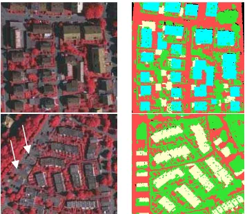
Figure 1: Aerial Images (left), Roof plane extraction (right): cyan – roofs, detected by azimuth constrains, white – flat and other oblique roofs, green – other objects (vegetation and non segmented points), red – terrain.
Nature of the constraint Statistics Azimuth threshold - for the roof pair ±3° deviation
Ridge-line horizontality < 3°
Slope constraint - for the oblique roof > 5° and < 75° Slope constraint - for the flat roof < 5°
Height threshold 2 meter
Table 1: Parameters for rules on roof segment extraction
After completion of the roof plane extraction, adjacent roof faces are assigned by a building number. As we do not have any additional data to demarcate the building boundaries, we assume that the entire connected roof planes should be represented by a single building, having ridge-lines and step-edges in between. Therefore, our next step is to reconstruct the inner bounds and is discussed in the next sections.
2.3
2.4
Ridge-lines and Step-edges construction
In general, inner bounds of a roof are mainly given by the ridge-lines and/or step-edge lines. The extraction of such features (i.e. feature-lines) between the adjacent roof planes provides the required vector data for inner polygon boundary of building model. Simultaneously, the information can be used to identify correct topological relationships among roof planes which we can later apply for the reconstruction of the outer bounds as well. (Oude Elberink, 2009; Verma et al., 2006) have shown a way of utilizing topological information in a form of a graph called roof topology graph. Similarly, we create roof topology graph while extracting the feature-lines.
Different measures can be used to assess in which situation an intersection line or a step-edge should be located at a common boundary between two segments. (Rottensteiner and Briese, 2003) use the rms error, while (Oude Elberink, 2009) use local distance thresholds to infer an intersection line. The latter measure is used, in a global form, for our approach and intersection lines are constructed by recognizing all the boundary points that lie within a narrow sharing zone along the common border. Half of the zone width is equal to the distance which is slightly less than twice the point spacing. At a common segment border, if every or higher percentage of boundary points can be separated from their nearest counter border points by height jumps, then there would be a step-edge. So that, the best fitted two line segments (up and down) are used to represent each step-edge. After generating a step-edge, the upper edge is recognized and planimetric coordinates of the edge terminals are then transferred to the down edge. The geometric regularization of the step-edges is carried out later, once the dominant building orientation is found.
Roof topology graph (RTG) construction
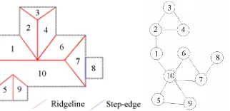
As described in the above section, the generation of a feature-line provides the necessary information to create a single graph line i.e. information on two vertices and an edge. A specific planar face is represented by a vertex whereas the topological relation between the two faces is basically represented by an edge of the RTG. “Ridge-line” and “Step-edge” are the only two possible relations that we accept for our graph edge and are represented by a unique label number. A complete RTG of a building can be constructed as shown in figure 2.
At this point, topological relationships between the roof segments are known and roof boundary delineation is remained.
For this, a new modelling approach based on the closed cycle graphs is introduced and discussed in section 3.
Figure 2: A complex roof structure (left) and its RTG, G (right)
2.5
3.1
Roof outline generation
Step-edges are weakly defined yet, thus their regularization can be performed with respect to the dominant building orientation. Since our graph construction is completed, the longest horizontal ridge-line (if any) or the longest outer line segment can be chosen as the dominant direction. For this reason, we extract all the boundary points of the whole connected components, through the contouring, and fit series of 3D line segments to represent building outer boundary in advance to the step-edge regularization.
3. CLOSED CYCLE ANALYSIS FOR INNER BOUNDS Assuming the G (figure 2) as a directed graph, different vertices can be chosen while traversing within the selected two end-vertices. For example, for the end-vertices 3 & 2, possible sets of vertices are; P1{3,2}, P2{3,4,2}, P3{3,4,6,10,1,2} and so on. Thus, we have more than one “path” to reach a given end node from a certain starting node. If the starting node becomes the end node, then the path will be a closed cycle, having a certain “length” (Pk, where k is the length). Consequently, above paths will become closed cycles C1, C2 and C3 such that C1={3,2,3}, C2={3,4,2,3} and C3={3,4,6,10,1,2,3}, having lengths (Ck) of 2, 3 and 6 respectively. As an initiation, we search closed cycles for a given edge which do not contain only that particular edge itself. So that the loop, having length two (e.g. C1) can be avoided and proceeded with other loops. However, considering the shortest path problem, cycles having higher degree of lengths can be disregarded and a unique ‘shortest’ closed cycle can be obtained for the given two end-vertices. As a result, assuming the RTG has equidistance edges, the well-known Dijkstra’s algorithm is applied to recognize every possible ‘shortest’ closed cycle that appears in a complete RTG graph. Finally, each RTG is decomposed into several shortest closed cycles having varying lengths which can be analyzed individually. Cycles having length 2, which appear as lines, will be recognized later, at the time of reconstruction of the roof outer boundary in this study.
Consequently, without knowing the roof primitive shapes, the geometric fitting of the roof corners associated with the ridge-line intersections can be robustly adjusted (figure 4). The other ends of the ridge-lines which are closer to the eaves or the gutters are reconstructed later, as described in section 4.
Figure 3: Convergence of Ridge-lines and Step-edges, at a closed cycle, (schematic diagram): red - ridges, blue - step-edges
Figure 4: Geometric fitting of roof corner, associated with ridge-lines: before (left) and after fitting (right)
3.2 Reconstruction of roof corners, relevant to step-edges In complex roof scenes, edges themselves and/or the step-edges & ridge-lines suppose to converge at more than one position, having the same planimetric coordinates with height jumps, and produce several roof corners (figure 5). The cycle analysis based on the 2D view is not sufficient to handle this case as relevant feature-lines reside on different planes at different height levels so that an advanced 3D view should be considered.
The number of planes or height levels depends on the number of edges which represent the “step-edge” label within a one cycle so that the cycle space should be split into different disjoined sections or “directed path graphs”. For example, the cycle space in figure 3 (right) is split into 2 disjoined sections, having edges in the order of {up, B, C-up} and {C-down, A-down} as there exist two height levels. In this case, the terminal ends of the path graphs are inserted with the terms ‘up’ and ‘down’ which tells us in which step-edge line is referring to that particular roof plane.
In case of the planimetric position, the top elevated roof corner having at least one ridge-line (if any, if not most top corner) is fitted first, and then other corners are fixed respectively (figure 5). During the process, step-edges are subjected to shift while preserving their direction based on the influence of the ridge-lines as ridge-ridge-lines are fixed in our approach. If two or more ridge-lines exist within a section, then we started from that corner as it can be defined with the most precision. In this way, every inner bound is adjusted and fixed. Geometrically valid closed polygons around the roof faces arethen reconstructed by adjusting the remaining outer bounds, as discussed in the next section.
4. OUTER BOUNDS FIXING
In the reconstruction of outer bounds, we assume, building bounds (eave lines) might be either parallel or orthogonal to the main building orientation when they deviate from a certain angular threshold. In this sense, previously fitted line segments are regularized with respect to the dominant direction, described in section 2.5. Afterwards, possible smoothens are
made in order to reduce the unusual irregularities, available within the consecutive parallel lines, exit on a same roof plane.
Figure 5: Geometric fitting of roof corner, associated with ridge-lines and step-edges: before (left), and after fitting (right)
Figure 6: Outer bounds fixing with roof skeleton
In addition to that, an important characteristic that could be considered in valid roof modelling is the geometrical fitting of outer roof corners and seamless connection of other intermediate outer bounds. In this case, inner roof skeleton can be directly taken into account. A feature-line of a roof skeleton frequently meet outer line segments in a way, making orthogonal corners or some regular corners deviate from 90°. In the orthogonal case, relevant outer line segments make a 180° angle themselves (spot 1 in figure 6) while in the latter case make 90° angles (spot 2, 3 in figure 6). Rather than an individual adjustment of each corner, a comparative adjustment of the roof corners helpful to achieve a geometrically correct 3D roof boundary. Therefore, we propose to fit such corners via the outer most cycle graph, available in the RTG, in an iterative manner.
Continuing the outer boundary reconstruction, testing of previously fitted line and currently fitted line, relevant to the two successive corners but associated with a same segment, is done in order to maintain the correct alignment of roof boundaries. This technique further assists to preserve the symmetric property of roof edges. Therefore, when a mismatch arises with the previous fitting, if it cannot be solved by the edge sweeping, then previously fitted corner is again fitted with respect to the current corner and one before previously with respect to the previously etc. Ultimately, the remaining intermediate line segments are intersected sequentially in between the two end lines of each laser segment. Some result of reconstructed roof models are shown in figure 7 and 8.
Figure 7: Generated L-Shaped roof structure with a height jump (left) and Complex connected roof (right): red – outer bounds, orange – ridge-lines, white – step-edges
5. RESULTS & DISCUSSION
original data (OD) set. The first scene contains 40 buildings and 115 roof planes while the second scene consists of 33 buildings and 49 roof planes. At present, the result is evaluated by manually with visual inspection.
In the classification, 0.5m height threshold is chosen for the measuring of segment discontinuities and all the building segments are correctly classified as the object segments except 2 buildings in test site 1. Although over 90% of roof planes (in OD), from the available figures, are detected by our rule based roof extraction algorithm, some vegetation patches are included inside the extraction. Furthermore, few flat and shed roofs, stay close to the terrain, are unable to detect due to the exceeding of constraints. The irregularity/regularity testing of segment boundary and minimum segment criteria, shared with the object adjacency largely rectify the erroneous roof detection. However, correct recognition of little vegetation patches, close to the roof planes and appears as regular polygon shapes, is difficult to fully achieve. Also, in the second test site, roof recognition has been misguided by a container yard (arrow in figure 1). Statistics of the roof extraction results is summarised in table 2.
During the RTG construction, fault adjacency of the roof segments is minimised by imposing a length criterion on feature-lines. Although, few roof corners are unable to fit due to the missing of one or more feature lines within the cycle, over 90% of inner bounds (from OD) are straightaway fixed, tightly, in respective buildings. The opening due to missing feature-lines is avoided by inserting the line segments at the time of closeness testing of the roof polygons at the end. Furthermore, over 80% of outer corners (from OD) are correctly fitted while preserving the geometric shapes. After fixing of the inner bounds, refinement on roof skeleton is also performed by averaging the z-coordinates of nearly horizontal ridge-lines.
In boundary point extraction, proper parameter tuning is important as the contouring of the segment boundaries highly sensitive to the point distribution and affected by the convex hull effect.
Test site 1 Test site 2
High Low High Low
# extracted roof planes 121 113 58 48
# correct extractions 112 100 44 40
Detection performance 98 94 90 81
Table 2: Summary of roof plane extraction
The problem of data gaps, occurred due to closely touched dormer edges with gutter lines, in boundary point extraction is considered in our process. For that, dormer segments, located fully inside or/and touched with an edge of the main roof faces are detected automatically and projected on to the main roof face in order to fill the gaps due to dormers. This technique assists for the extraction of real roof boundary points (without concave holes) along the eave lines via contouring (figure 9, right).
Furthermore, correct geometry of the roof boundary is maintained during the modelling process. In this case, flexible edge sweeping is adopted with respect to a shifting threshold and maintain the boundary alignment. For instance, the case where outer bounds intersect corresponding feature-line at two different positions having a considerable gap (figure 9); then the constraint doesn’t allow for sweeping of the edges.
Additionally, the cases where missing outer bounds occur due to less number of boundary points, for instance at elongated thin small roof faces, are rectified by inserting an orthogonal line segment in between the available adjacent edges (figure 10).
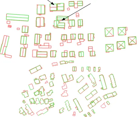
Figure 8: Visual appearance of roof models: red - 3D roof models reconstructed from high density data, green – with low density data (for the clarity, aerial view is chosen)
The forward and backward iteration step is utilized in order to rectify the common problem on boundary reconstruction i.e. non- coincidence of outer bounds and inner skeleton at the roof corners. Subsequently, a mis-closure, presented at the end of the process, is redistributed to preserve the geometry of the building.
Figure 9: Maintaining the correct boundary shape (left) and Roof models with dormers, after gap filling (right)
Figure 10: Gaps due to less number of points is solved (left) and error due to missing data on a flat roof (right)
modelled as separate buildings in low density data (arrows in figure 8). In this end, locally, self adaptable constraints are promising and will be adopted as a future work.
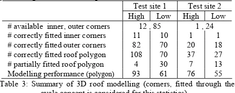
Test site 1 Test site 2 High Low High Low # available inner, outer corners 12 , 85 1 , 24
# correctly fitted inner corners 11 10 1 1
# correctly fitted outer corners 82 70 20 18
# correctly fitted roof polygon 108 70 37 27
# partially fitted roof polygon 4 30 7 13
Modelling performance (polygon) 93 61 76 55 Table 3: Summary of 3D roof modelling (corners, fitted through the
cycle concept is considered for this statistics)
The whole workflow is fully automated and performed with few user defined parameters. Although, some invalid RTG (and then cycles) is obtained due to some segmentation issues (over/under segmentation) and fault recognition of segment adjacencies, the developed method is promising for the reconstruction of complete 3D roof structures in complex urban environments.
6. CONCLUSION & OUTLOOK
The results show that topologically correct detailed roof models can be reconstructed by our method. The advantage of our approach is that the different roof structures can be reconstructed without identification of their primitive shapes. Over 80% of correct corner fitting (inner corners), in low density data, depict the robustness of corner fixing by close cycle graph concept. However, missing of the feature-lines within a cycle and invalid topological relationship invalidate the correct fixing of roof corners. Hence, correct recognition of constraints and validity of the segmentation step are significant in data driven reconstruction workflow. More accurate roof models are given by the high density data. Results on roof extraction together with vegetation removal reveal that our developed approach is considerable for the urban environment. However, few roof planes are incorrectly identified as polygons having irregular borders due to the problem of missing data and merging of close vegetation.
The geometric accuracy of the roof edges should be further increased so that the boundary refinements will be made by combing the image data in future.
ACKNOWLEDGEMENT
The Vaihingen data set was provided by the German Society for Photogrammetry, Remote Sensing and Geoinformation (DGPF) [Cramer, 2010]: http://www.ifp.uni-stuttgart.de/dgpf/DKEP-Allg.html (in German). The author wishes to thank the organizers of the ISPRS Commission III/4 for providing the data and Prof. G. Vosselman for enabling the use of mapping tools and library.
REFERENCES
Dorninger, P. Pfeifer, N., 2008. A Comprehensive Automated 3D Approach for Building Extraction, Reconstruction, and Regularization from Airborne Laser Scanning Point Clouds. Sensors, 8(11): 7323-7343.
ISPRS Commission III, 2011, "ISPRS Test Project on Urban Classification and 3D Building Reconstruction".
http://www.isprs.org/news/announcements/110314_ISPRS_Inte rcomparison-Flyer.pdf (02.01.2012).
Khoshelham, K., 2005. Region Refinement and Parametric Reconstruction of Building Roofs by Integration of Image and Height Data. In: International Archives of Photogrammetry and Remote Sensing and Spatial Information Sciences, Vol XXXVI, Part 3/W24, pp. 693-698.
Maas, H.G., and Vosselman. G., 1999, Two algorithms for
extracting building models from raw laser altimetry data, ISPRS
Journal of Photogrammetry & Remote Sensing, 54(2-3):
153-163.
Milde, J., Zhang, Y., Brenner, C., Pluemer, L. and Sester, M., 2008. Building Reconstruction using Structural Description based on a Formal Grammar. In: International Archives of Photogrammetry, Remote Sensing and Spatial Information Sciences, XXXVII, part 3B: pp. 227-232.
Oude Elberink, S. and Vosselman, G., 2009. Building Reconstruction by Target Based Graph Matching on Incomplete Laser Data: Analysis and Limitations. Sensors, 9(9): 6101-6118.
Oude Elberink, S., 2010. Acquisition of 3d topography: automated 3d road and building reconstruction using airborne laser scanner data and topographic maps. Ph.D. dissertation, University of Twente, Enschede, The Netherlands.
Perera Nirodha S., 2007. Segment based filtering of LASER scanner data, Master thesis, ITC, The Netherlands.
Rottensteiner, F., and Briese, C., 2003. Automatic Generation of Building Models from Lidar Data and the Integration of Aerial Images. In: International Archives of Photogrammetry, Remote Sensing and Spatial Information Sciences, XXXIV, part 3/W13: pp. on CD-ROM.
Rottensteiner, F., Trinder, J., Clode, S., and Kubik, K., 2005. Automated delineation of roof planes from lidar data. In: International Archives of Photogrammetry and Remote Sensing and Spatial Information Sciences, Vol. XXXIV, 3/W19, the Netherlands.
Schwalbe, E., Maas, H.-G., and Seidel, F., 2005, 3D building model generation from airborne laser scanner data using 2D GIS data and orthogonal point cloud projections. In: International Archives of Photogrammetry and Remote Sensing and Spatial Information Sciences, Vol XXXVI, Part 3/W19, pp. 209-213.
Verma, V., Kumar, R. and Hsu, S., 2006. 3D Building Detection and Modeling from Aerial LIDAR Data, IEEE Computer Society Conference on Computer Vision and Pattern Recognition (CVPR'06). IEEE Computer Society, Washington, DC, USA, pp. 2213-2220.
Vosselman, G., 1999. Building Reconstruction Using Planar Faces in Very High Density Height Data. In: International Archives of Photogrammetry, Remote Sensing and Spatial Information Sciences, XXXII, part 3/2W5: pp. 87-92.