MOBILIZATION OF MINI PILE UPLIFT RESISTANCE IN SAND
Andikanoza Pradiptiya1, Yuwono2, Handi Sudardja3 and Istiatun4
Department of Civil Engineering, State Polytechnic of Jakarta Email : 1[email protected],
Abstract
Shaft resistance of tension pile will be fully mobilized at certain displacement. Some structures impose limits to the displacement of pile with a relatively small value in order not to cause damage. Therefore, it is necessary to know the behavior of pile resistance reaction against load that works in every displacement.
The study was conducted using the model of single pile made of concrete with a length of 0,2 m ; 0,3 m ; 0,4 m and each diameter 0,02 m ; 0,03 m ; 0,04 m. The model pile is jacked in sand that has been compacted in a box and then given uplift load that refers to the ASTM D3689-07 procedure E. Pile resistance reaction is shown by pile friction modulus and determined by mobilized unit shaft resistance and pile displacement relationship.
The results showed that mobilization of uplift resistance of mini pile that has been counted using friction modulus can only approach the value of true observations, so that it requires further consideration as design parameter.
Keywords : Mini pile, sand , uplift resistance.
INTRODUCTION
Tension pile bearing capacity is strongly determined by shaft resistance than end bearing. Shaft resistance occurs on pile shaft that is in contact with soil and it will be fully mobilized at certain displacement. Some structures impose limits to the displacement of piles with a relatively small value in order not to cause damage. For example is application of piles and rigid pavement combination or called nailed slab system that is expected to prevent cavity between plate and ground to keep the piles displacement remains relatively small to the ground. Small pile displacement may indicate that shaft resistance has not been fully mobilized. Therefore, it is necessary to know the behavior of pile resistance reaction that works in every displacement by conducting it in Laboratorium using model of pile. Pile resistance reaction is shown by pile friction modulus (kt) and determined by mobilized unit shaft resistance (Rs) and pile displacement (δ) relationship.
Pile Modulus Friction (kt)
Pile friction modulus (kt) is mobilized unit shaft resistance (Rs) and pile displacement (δ) relationship [1].
Generally, pile load-displacement (F-δ) curves will show a non-linear tendency. The curve can be converted into a Rs and
δ relationship so that an auxiliary linear curve can be interpreted from the tangent modulus and secant modulus which would give a pile friction modulus (kt). Interpretation value of kt from Rs and δ relationship can be seen in Figure. 1. Pile friction modulus, kt in Figure. 1 is defined as:
Rs = mobilized unit shaft resistance
(kN/m2)
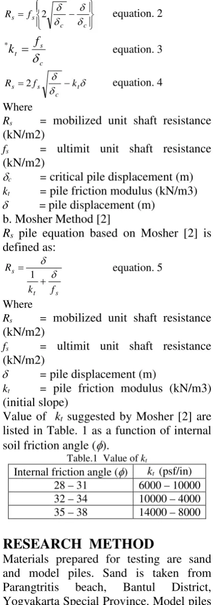
Mobilized Unit Shaft Resistance (Rs) Based on Pile Friction Modulus (kt)
a. Vijayvergiya Method (1977)
Rs = mobilized unit shaft resistance
(kN/m2)
fs = ultimit unit shaft resistance
(kN/m2)
δc = critical pile displacement (m) kt = pile friction modulus (kN/m3) δ = pile displacement (m)
Rs = mobilized unit shaft resistance
(kN/m2)
fs = ultimit unit shaft resistance
(kN/m2)
δ = pile displacement (m)
kt = pile friction modulus (kN/m3)
(initial slope)
Value of kt suggested by Mosher [2] are listed in Table. 1 as a function of internal soil friction angle (φ).
Materials prepared for testing are sand and model piles. Sand is taken from Parangtritis beach, Bantul District, Yogyakarta Special Province. Model piles can be seen in Figure. 2
Pile head is given a thin slab of Acrylic as a place to put a dial gauge for measuring the pile displacement. Equipment that is
Testing Box is 120 cm in length, 120 cm in width , 120 cm in height and made of reinforced polymer materials with reinforcement elbow.
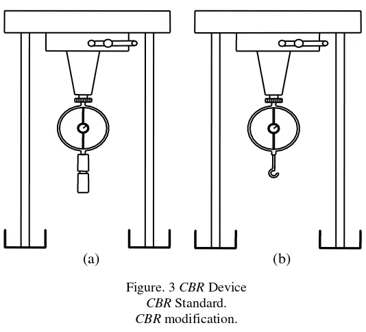
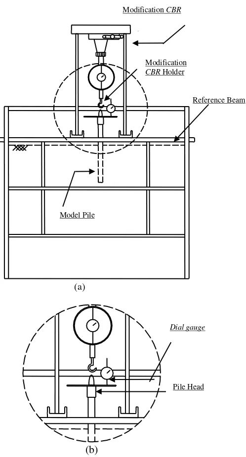
Model piles are jacked on distance of each by 30 cm. CBR tool is modified by changing the pressure to be device to test the hooks to be used to apply tensile force to the pile foundation model as shown in Figure. 3. Position cbr modification in Figure. 4 should be symmetrically on model pile so that application of a uplift load is expected to be exactly on model pile axis. Dial gauge used to measure pile displacement fastened to a block of reference so that dial is fixed and remain stable.
Investigation consists of a preliminary test and main test. Preliminary test is physical and mechanical properties of soil and the main test is done by giving uplift load on model pile using CBR modification, loading method refers to ASTM D3689-07 procedure E.
TEST RESULTS
Preliminary test results of Sand
Specific gravity (Gs) of sand is 3,14 with 99,76% sand, 0.2% gravel and 0,04% silt.
Sand is classified based on Unified Soil Clasification System as poorly graded sand and distributeduniformly orSP. γdmax of sand is 1,90gr/cm3 withwater content (w) 9,05%
while the value of γdmin is 1,70 gr/cm3 with dry conditions. Relative density (Dr) in the box is around 89,37%. Direct shear test on sand produces internal friction angle (φ) = 37,23oandcohesion(c) ≈ 0kN/m2 so thatcan
generally be assessed in a relatively dense conditions.
Main Test Results
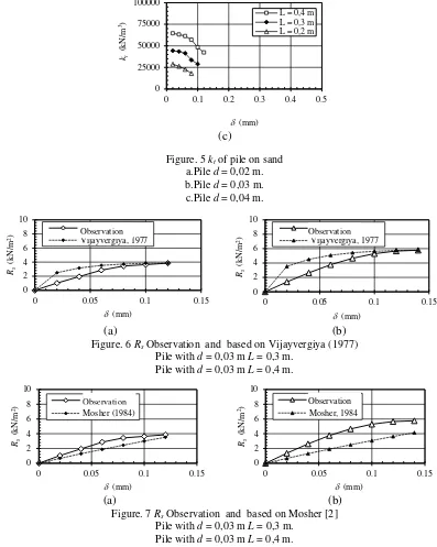
Pile friction modulus (kt) at pile displacement (δ) up to a critical displacement (δc) of each pile in sand are shown in Figure. 5.
0,03 m L = 0,4 m are shown in Figure. 6 and Figure 7.
Rs by Mosher [2] is smaller than Rs
observations, and Rs based on
Vijayvergiya (1977) will be closer to Rs observation with increasing displacement (δ) until it reaches a value equal to the observations pile critical displacement (δc).
CONCLUSIONS
Pile friction Modulus (kt) is reduced with
increasing pile displacement (δ). Mobilzed unit shaft resistance (Rs) by Mosher [2] is smaller than Mobilzed unit shaft resistance (Rs) observations.
Mobilzed unit shaft resistance (Rs) based on Vijayvergiya (1977) is smaller than Mobilzed unit shaft resistance (Rs) observations and will be closer to
Mobilzed unit shaft resistance (Rs) observation with increasing δ until it reaches a value equal to the observations pile critical displacement (δc).
Mobilization of uplift resistance of mini pile that has been counted using friction modulus can only approach the value of true observations, so that it requires further consideration as design parameter.
REFERENCES
[1] Hardiyatmo, H. 2011. Method to Analyze The Deflection of The Nailed Slab. International Journal
of Civil & Environmental
Engineering , p.22-28.
[2] Mosher, R., & Dawkins, W. 2000.
Figure.1 Interpretation value of kt
(a) (b) (c)
Figure. 2 Mini Pile Model
d = 0,04 m dengan L = 0,4 m, 0,3 m, 0,2 m. d = 0,03 m dengan L = 0,4 m, 0,3 m, 0,2 m. d = 0,02 m dengan L = 0,4 m, 0,3 m,0,2 m.
(a) (b)
Figure. 3 CBR Device CBR Standard. CBR modification.
Tangent Modulus
Secant Modulus
δ Rs
3 2
m kN m m kN R
k s
t = δ = =
(a)
(b)
Figure. 4 CBR modificationi dan dial gauge arrangement Position of CBR modification is on test box
Model pile and dial gauge detail position
(a) (b)
0 25000 50000 75000 100000
0 0.1 0.2 0.3 0.4 0.5
kt
(k
N/
m
3)
δ (mm)
L = 0,4 m L = 0,3 m L = 0,2 m
0 25000 50000 75000 100000
0 0.1 0.2 0.3 0.4 0.5
kt
(k
N/
m
3)
δ (mm)
L = 0,4 m L = 0,3 m L = 0,2 m Pile Head
Dial gauge Model Pile
Reference Beam Modification CBR
(c)
Figure. 6 Rs Observation and based on Vijayvergiya (1977)
Pile with d = 0,03 m L = 0,3 m.
Observation Observation