Design, Fabricate, and Performance Study of an Exhaust Heat-driven Adsorption Air-conditioning System for Automobile
LEO SING LIM
A thesis submitted
in fulfillment of the requirements for the degree of Doctor of Philosophy
F acuIty of Engineering
UNIVERSITI MALA YSIA SARAW AK
2009
ACKNOWLEDGEMENT
This thesis research based project could not be completed without the assistance and support of several individuals to whom the author wish to express his deepest gratitude. First of all, the author wishes to take this opportunity to sincerely thank his supervisor, Dr. Hj.
Mohammad Omar Abdullah for his kind supervision, guidance and motivation given to see through the success of this project. The author also would like to give a special thank to his parent, wife and son for their support and encouragement throughout the research work.
Apart from that, the author also wishes to thank all mechanical lab assistants for providing full assistance in ensuring the completion of his laboratory works. A sign of gratitude is also forwarded to the Ministry of Science, Technology and the Environment for their financial support awarded through the Zamalah KSTI (Ministry of Science, Technology and Innovation). Last but not least, the author would also like to note the motivation and support given by his friends throughout this research project.
III (
ABSTRACT
Adsorption cooling systems powered by waste heat or solar heat can help to reduce the use of ozone depletion substances, such as chlorofluorocarbons (CFCs) and hydro- chlorofluorocarbons (HCFCs). In recent years, this system has witnessed an increasing interest in many fields due to the fact that this system is quiet, long lasting, cheap to maintain and environmental friendly. In this research work, a novel prototype of automobile adsorption air-conditioning system powered by exhaust heat has been successfully built and tested in laboratory. The working pair used is local produce palm-derived activated carbon and 1
.
methanol, where activated carbons act as an adsorptive substance and methanol as refrigerant.
This system consists of two adsorbers, a blower, evaporator with a blower, expansion valve, a condenser with a fan, valves, an engine and some pipe connectors. Two identical adsorbers were constructed and operated intermittently to provide continuously cooling effect. The working pressure of the system is below 0.1 bars and no leakage. The system was initially charged with 400 mL of methanoL Variation of temperature for the entire system and some components of the system during operational were presented by using images captured from thermography camera. Experiments on various pressure regulating devices revealed the utilization of 0.5 mm orifice tube provide the lowest cooling temperature in a shortest time compared to common thermal expansion valve. The experimental results showed the chilled air temperature at approximately 22.6
°c
was produced for space cooling. The COP of automobile adsorption air-conditioning system was calculated to be approximately 0.19 while the SCP was around 396.6 Wkg-l. The conclusion drawn from the current work is that the adsorption technology, as prescribed in this work, is feasible and promising for automobile air-conditioning purpose; however, there is a need to further enhance the efficiency and the associated control system for effective on-the-road application .,
REKA BENTUK, PEMBINAAN DAN KAJIAN TERHADAP SISTEM PENYAMAN UDARA JENIS PENJERAPAN MENGGUNAKAN HABA EKZOS KENDERAAN
ABSTRAK
Sistem penyaman udara jenis penjerapan dengan menggunakan kuasa haba terbuang dan suria dapat mengurangkan penggunaan bahan-bahan yang boleh menyebabkan penipisan ozon seperti chlorofluorocarbons (CFCs) dan hydro-chlorofluorocarbons (HCFCs). Sejak kebelakangan ini, penggunaan sistem penjerapan telah menyakslkan peningkatan dalam pelbagai bidang kerana sistem ini adalah senyap, tahan lama, kos penyelenggaraan yang
, f
rendah dan tidak merosakkan alam sekitar. Dalam kerja penyelidikan ini, satu prototaip sistem penyaman udara jenis penjerapan yang dikhaskan untuk kenderaan telah berjaya dicipta dan dikaji di dalam makmal. Pasangan bahan yang digunakan untuk bertindak sebagai penyerap ialah karbon beraktif yang dihasilkan daripada temperung kelapa sawit manakala bahan yang dijerap ialah metano/. Prototaip ini terdiri daripada dua penjerap, satu peniup udara, sebuah kondenser dengan peniup udara, satu injap pengembangan, sebuah penyejat dengan kipas, beberapa buah injap kawalan, sebuah enjin empat lejang dan beberapa batang paip penyambung. Dua penjerap yang serupa telah direka dan dibina untuk memberi kesan penyejukan yang berterusan melalul kaedah pemanasan dan penyejukan
..
,penjerap-penjerap terse but secara berselang-seli. Setiap penjerap pula mengandungi dua katil penyerap yang dipenuhi dengan 0.8 kg butir karbon beraktifpada setiap kati/. Tekanan di dalam sistem ini adalah amat rendah iaitu di bawah 0.1 bar dan sebarang kebocoran perlu dielakkan supaya prototaip dapat berfungsi dengan balk. Sebanyak 400 mL methanol telah disuntik ke dalam sistem sebeZum operasi. Perubahan suhu pada keseluruhan sistem dan juga pada beberapa bahagian utama slstem semasa sedang beroperasi telah dipersembahkan melaZul gambar-gambar yang dlperolehi dengan menggunakan sebuah
kamera termografik. Eksperiment-eksperiment telah dijalankan untuk mengkaji beberapa jenis alat pengawal tekanan dan keputusan eksperiment menunjukkan bahawa penggunaan tiup orijis dengan diameter 0.5 mm menghasilkan suhu yang agak rendah pada masa yang singkat berbanding dengan penggunaan injap pengembangan suhu yang biasa. Dengan penggunaan injap tersebut, suhu udara yang ditiup keluar daripada penyejat adalah serendah 20.5 °C untuk tujuan pendinginan ruang di dalam kenderaan. Pekali perlaksanaan (COP) untuk sistem ini adalah sekitar 0.19 manakala kuasa penyejukan spesijik ialah 396.6 Wkg-J• Keputusan daripada eksperiment-ekperiment menunjukkan bahawa penggunaan teknologi penjerapan dalam penyaman udara kenderaan boleh menjadi salah satu alternative yang amat baik untuk menggantikan sistem pemampat wap pada masa depan. Walau bagaimanapun, penambahbaikan perlu dilakukan untuk meningkatkan kecekapan dan sistem kawalan yang berkaitan sebelum prototaip ini dapat diuji di atas jalan.
.. ,
TABLE OF CONTENTS
Page
ACKNOWLEDGEMENT 11
TABLE OF CONTENTS Vi
LIST OF FIGURES Xi
ABSTRACT III
LIST OF TABLES XIV
NOMENCLATURE xv
CHAPTER 1 INTRODUCTION 1
1.1 Introduction 1
1.2 History of Air-conditioning 2
1.3 Issue of Conventional Refrigerant's 4
1.4 Objective ofthe Research 6
1.5 Organization of the Thesis 7
CHAPTER 2 THEORETICAL BACKGROUND 9
2.1 Conventional Vapor-compression System 9
2.1.1 Typical components in vapor-compression system 12
2.1.1.1 Compressor 12
2.1.1.2 Condenser 14
2.1.1.3 Evaporator 15
...
I 2.1.1.4 Pressure regulating devices 16
2.1.1.5 Receiver-drier 18
2.1.1.6 Accumulator 19
2.1.1.7 Other components 20
2.1.2 Thermodynamics analysis of vapor compression cycle 21
2.2 Sorption Air-cooling Technologies 23
2.2.1 Adsorption cycle 24
2.2.1.1 Basic adsorption cycle 25
2.2.1.2 Mass recovery adsorption cycle 26 2.2.1.3 Continuous heat recovery adsorption cycle 26
2.2.1.4 Thermal wave cycle 27
2.2.1.5 Cascading cycle 29
2.2.2 Absorption cycle 29
2.2.3 Desiccant cycle 30
2.3 Principle of Adsorption 32
2.3.1 Adsorption equilibrium 33
4- 2.3.2 Type of solid adsorbents 36
2.3.2.1 Hydrophilic solid adsorbents 37
2.3.2.2 Hydrophobic solid adsorbents 38
2.3.3 Working pairs and their heat of adsorption 43 2.3.4 Heat and mass transfer inside the adsorbent bed 35 2.3.5 Thermodynamics Analysis of Adsorption Cycle 45
49 2.3.6 Perfonnance of the adsorption cycle
CHAPTER 3
\
..
CHAPTER 4
2.3.6.1 Coefficient of Perfonnance 49
2.3.6.2 Specific Cooling Power 49
2.4 Adsorption Cooling System versus Vapor Compression System 50
LITERATURE REVIEW 52
3.1 Adsorption System Development 52
3.2 Adsorbent-adsorbate Pairs of the Adsorption Cooling System 59 3.2.1 Activated carbon and alcohol systems 59
3.2.2 Zeolite and water systems 60
3.2.3 Zeolite composites and water systems 61
3.2.4 Silica-gel and water systems 61
3.2.5 Activated carbon and ammonia systems 61 3.2.6 Metal hydrides and hydrogen systems 62 3.3 Adoption of Adsorption Cooling Technologies in Automobile 62
3.4 Current Research Work 68
METHODOLOGY AND EXPERIMENTAL SETUP 71
4.1 Exhaust Heat-driven Adsorption Air-conditioning System 71
4.2 Working Pairs 72
4.2.1 Activated carbon 72
4.2.2 Methanol 74
4.3 Prototype Setup 75
}
4.3.1 Construction of the adsorbers 75
4.3.2 Characteristics of the engine 78
4.3.3 Condenser 78
4.3.4 Evaporator 80
4.3.5 Other components 81
4.3.6 Instrumentations 81
4.4 Integration and Commissioning of the Prototype 82
4.5 Operational of the Prototype 83
4.6 Scopes and Limitations 89
4.6.1 Scopes 89
4.6.2 Limitations 89
CHAPTER 5 RESULTS AND DISCUSSIONS 91
5.1 Operational Conditions 91
5.1.1 Variation of temperature in the system 91
5.1.l.1 Entire system 92
5.1.1.2 Adsorbers 94
5.1.1.3 Condenser 94
5.1.1.4 Evaporator 96
5.2 Experiments on Various Type of Pressure Regulating Devices 97 5.3 Experiments on Variation of Temperature during Cooling 99
Operation
CHAPTER 6 CONCLUSIONS AND RECOMMENDATIONS FOR FUTURE 108 WORK
6.1 Conclusions 108
6.2 Recommendations for Future Work III
REFERENCES 113
APPENDIX 123
LIST OF FIGURES
Figure Page
1. Single stage vapor-compression cycle. 9
2. Conventional automobile air-conditioning system. 11
3. Compressor and clutch. 12
4. Type of compressors. 13
5. Condenser. 15
6. Evaporator coiL ] 6
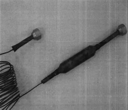
7. Orifice tube. 17
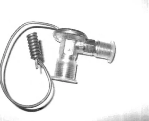
8. Thermal expansion valve. ] 8
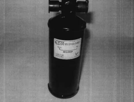
9. Receiver-drier. 19
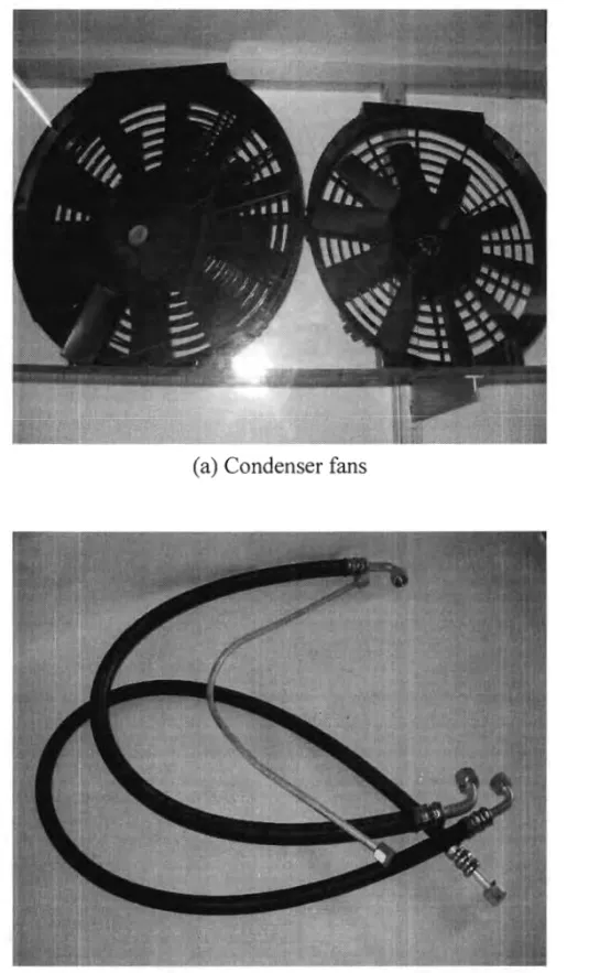
10. Condenser fans, hoses and aluminum pipes. 20
11. Temperature versus entropy diagram for a conventional vapor- 21 compression cycle air-conditioning system.
12. Sorption system. 24
13. Ideal adsorption cycle. 25
14. Schematics diagram of the two-bed heat recovery adsorption 26 refrigeration system.
15. Schematic diagram of the thermal wave cycle. 28
16. An open solid desiccant cycle. 31
17. Adsorption process. 32
18. Type of solid adsorbents. 36
19. A simple adsorption cooling system. 32
20. T -S diagram of an ideal adsorption single-effect system. 46
21. P-T-X diagram of an adsorption cycle. 47
22. Schematic diagram of a solar powered ice-maker. 53
23. Adsorption refrigerator invented by Patzner (2001). 54
24. Adsorption refrigerator invented by Monma and Mizota (2005). 56 25. Schematic diagram of adsorption air-conditioning system for electric 63
vehicle by Aceves (1996).
26. Schematic diagram of an adsorption air-conditioner for buses driven by 65 the waste heat from exhausted gases by Wang et al. (2001).
27. Schematic diagram of locomotive driver cabin air-conditioner by Lu et 67 al. (2004).
28. Schematic diagram of the prototype. 71
29. Palm-derived activated carbon. 73
30 SEM image of palm-derived activated carbon. 73
31. Design of the adsorbers with CATIA software. 76
32. Cross-section of the adsorber element. 77
33. Four-stroke EY20-3 Subaru Robin 5.0 HP engine. 78
34. Front and back views of the condenser. 79
35. Hanging type evaporator. 80
36. Experimental setup 82
;
37. Schematic diagram of the automobile adsorption cooling system 84 ( Adsorber 1 in desorption phase while Adsorber 2 in adsorption phase).
38. Schematic diagram of the automobile adsorption cooling system 85 (Adsorber 1 in adsorption phase while Adsorber 2 in desorption phase).
39. Simple T-S diagram ofthe automobile adsorption system. 92 40. Temperature variation ofthe entire system before operation. 93 41. Temperature variation of the entire system during operation. 93 42. Temperature variation of the exhaust pipe during operation. 94 43. Temperature variation of the adsorbers during operation. 95 44. Temperature variation of the condenser during operation. 95 45. Temperature variation of the evaporator during operation. 96 46. Temperature variation of the evaporator inlet and outlet. 97 47. Cooling generated with various types of pressure regulating devices. 98 48. Variation of temperatures during adsorption cooling process. 101 49. Variation of temperatures for the cooling coil and cooling space during 102
operation.
50. Variation of temperatures for the cooling coil. 103
51. Variation of temperatures for the chilled air. 104
•
LIST OF TABLES
Table Page
1. Timetable for refrigerant phase-out in the European Union. 5 2. Advantages and disadvantages of absorption cooling system. 29 3. Advantages and disadvantages of desiccant cooling system. 31
4. Total pore volume and surface area for some of the activated carbon. 39
5. Various forms of activated carbon. 42
6. Some of the common working pairs and their heat of adsorption. 44
7. General comparison between vapor-compression system and the 51 adsorption system.
8. Some of the development in adsorption technologies. 57 9. Some of the developments in automobile air-conditioning technologies. 68
10. Properties of the activated carbon. 74
11. Properties of the methanol. 73
12. Specification ofthe condenser. 80
13. Specification of the evaporator. 81
14. Adsorbers operating phases. 88
15. Operational conditions of the system. 91
16. Operating design temperatures. 105
1 7. Parameters used to calculate SCP. 106
NOMENCLATURE
Symbol
COP Coefficient ofPerfonnance SCP Specific Cooling Power (Wkg-') C specific heat capacity (kJkg-'K-1) D constant in DA equation
E interaction energy between absorbent and adsorbing molecules (Jmor')
,
h enthalpy (kJ/kg) isosteric heat (kJ/kg)
m mass (kg)
m mass flow rate ofthe adsorbate (kgs-')
n characteristic constant of adsorbent represent with small integer P pressure (mbar)
saturated pressure of adsorbate in liquid fonn (bar) adsorbate pressure in vapor fonn (bar)
Q
heat (J)'It ,
Q rate of heat transfer to the adsorbate (Js-')
m
rate of heat transfer from the adsorbate (1s-') Q(Jut
Qaux total auxiliary energy input (kJ)
Qload cooling provided by the system (kJ)
R universal gas constant (Jmor'K-1)
W rate of power input (JS·I)
W volume of the micro-pores in the adsorbent that is filled with adsorbate (m3/kg) Wo total volume of the micro-pores (m3/kg)
Greek Symbols
E adsorption potential (lmorl) P density (kg/m-3)
Subscripts
a adsorbent
ad adsorbate (refrigerant)
Ad Adsorber
ads adsorption
am ambient
c condenser
com compressor
de desorption
ev evaporator
i initial
iso isosteric
CHAPTER 1 INTRODUCTION
1.1 Introduction
In general, the automobile air-conditioning system is a combination of heater and refrigerant circuit. This allows the generation of the desired indoor air conditions, which is completely independent of the outside conditions. As a result, the air conditioning is an essential factor for safety and also traveling comfort. However, refrigeration and air-conditioning technology is required to evolve due to the new environmental regulation (Montreal protocol in 1987).
The regulation is concerning about the depletion of the ozone layer, which decided to phase
out chlorofluorocarbons (CFCs) and followed by hydro-chlorofluorocarbons (HCFCs). This trend leads to a strong demand of new systems for space cooling. Among the proposed cooling technologies, the adsorption cooling system has a very good potential. The advantages of this system are it is quiet, long lasting, cheap to maintain, non-polluting refrigerants and environmental friendly (Dieng & Wang, 2001).
In the past, adsorptive processes have been widely used for catalysis and gas
,
,
separation. As adsorption technology evolved, a lot of research was carried out (especially in China, United State of America, and Japan) to study the application of this technology for space cooling and refrigeration (Boubakri et aI., 2000; Douss & Meunier, 1989; El Fadar et al., 2009; Endo & Komori, 2005; Grenier et al., 1998; Jiangzhou et al. 2005; Lemmini &
Errougani, 2005; Li & Wu, 2009; Pons & Guileminot, 1986; Wang, 2001a; Xia et al. 2009) . According to ASHRAE (1972), adsorption cooling system is one of the potential thermal
adsorption system will make them as the most environmental friendly cooling alternative from every aspect; including ozone depletion potential, global warming potential and primary energy consumption. Thus, adsorption system can be a good alternative to conventional vapor-compression machines in the future.
Adsorption refrigeration cycle powered by solar energy or waste heat exhausted from engines has been successfully used for ice making and cold production. For example, solar adsorption ice maker (Boubakri et al., 2000; Lu et al., 2006), zeolite-water solar cold storage system (Lu et al., 2003), carbon-ammonia solar refrigerator for vaccine cooling (Critoph, 1994)., and a silica gel-water adsorption refrigeration cycle driven by waste heat of near- ambient temperature have been reported by Saha et al. (2001). Dieng and Wang (2001) have stimulated several theoretical and experimental studies on adsorption cooling systems. They also gave useful guidelines regarding the designs parameters of adsorbent bed reactors, and the applicability of solar adsorption for both air-conditioning and refrigeration purposes.
1.2 History of Air-conditioning
,
, ,A long time ago, the ancient Romans were known to circulate water through the walls of certain houses in order to cool them. However, only the wealthy could afford such a luxury cooling as this sort of water usage was expensive at that time. In 1820, British scientist and inventor Michael Faraday have discovered that by compressing and liquefying ammonia could chill air when the liquefied ammonia was allowed to evaporate. Dr. John Gorrie, a physician from Florida in 1842, has utilized compressor technology to create ice for cooling his patients in Apalachicola hospital. He hoped eventually to use his ice-making machine to
t
regulate the temperature of the buildings. In 1851, he was granted a patent for his ice-making machine although his prototype leaked and performed irregularly. Unfortunately, his hopes for its success vanished when his chief financial backer died. Dr. Gorrie died impoverished in 1855 and the idea of air conditioning faded away for 50 years.
The early commercial applications of air conditioning were manufactured to cool air for industrial processing rather than personal comfort. In 1902, Willis Haviland Carrier was invented the first modem electrical air conditioning. His invention was designed to improve the manufacturing process control in a printing plant by controlling not only the temperature but also the humidity. In this case, the low heat and humidity were needed to help maintain consistent paper dimensions and ink alignment. As technology evolved over time, air conditioning is used to improve comfort in residential houses and also in automobiles.
Normally, these air conditioners employed ammonia, propane and methyl chloride as a refrigerant.
In 1928, Thomas Midgley, Jr. created the first chlorofluorocarbon gas known as Freon. This refrigerant is safe but was later found to be harmful to the atmosphere's ozone layer. In general, "Freon" is a trade name of Dupont for any Chlorofluorocarbon (CFC), Hydrogenated CFC (HCFC), or Hydrofluorocarbon (HFC) refrigerants. HCFC known as R
22 is the most commonly used in direct-expansion comfort cooling. Several non-ozone depleting refrigerants have been developed as alternatives, such as R-4lOA. R-41OA also known by the brand name as "Puron". As evolvement in air conditioning technologies continue, recent emphasis is on energy efficiency and also for improving indoor air quality.
1.3 Issue of Conventional Refrigerants
Chlorofluorocarbons (CFCs) and hydro-chlorofluorocarbons (HCFCs) refrigerants were dominated the refrigeration and air-conditioning market before the Montreal Protocol was adopted in 1987. The popularity of fluorocarbons used in refrigeration and air-conditioning system is based on three important properties they present, which are:
• good compatibility with the component materials in the system,
• zero flammability, and
• low toxicity.
151
On October 2000, a new European Commission regulation on ozone layer depleting substances, Regulation 2037/2000, was implemented (Papadopoulos et ai., 2003).
This regulation treats the whole spectrum of control and phase-out schedule (as shown in Table 1) for all ozone depleting substances, especially for CFCs and HCFCs. As a result, this regulation will enforce the penetration of either alternative refrigerants or alternative refrigeration technologies.
Although there are various types of new refrigerants in the market that have been specifically developed to address the phase out of CFCs and HCFCs, only five important global refrigerant options remain for the vapor compression cycle. These refrigerants are:
• hydro fluorocarbons (HFCs, HFC-blends with 400 and 500 number designation),
• hydrocarbons and blends (HCs, e.g. HC-290, HC-600, HC-600a etc.),
• ammonia (R-717),
• carbon dioxide (C02 , R-744), and
• water (R-718).
Table 1: Timetable for refrigerant phase-out in the European Union (Papadopoulos et al., 2003).
Date Remarks
11112001 • CFCs banned for servicing and maintaining existing system
• Recovered CFCs must be destroyed
• HCFCs banned in new systems above 100 kW cooling capacity 1/7/2002 • HCFCs banned in new systems below 100 kW cooling capacity
• 15% cut in supply of new HCFCs 11112003 • 55% cut in supply of new HCFCs
111/2004 • HCFCs banned in new reversible and heat pump systems
• 70% cut in supply of new HCFCs
1/1/2008 • Review the alternatives for HCFCs (Ban on HCFCs for servicing and maintaining existing systems might be brought forward)
• 75% cut in supply of new HCFCs
111/2010 • Virgin HCFCs banned for maintaining and servicing existing systems
• Total ban on supply of new HCFCs
11112015 • All HCFCs banned for maintaining and servicing existing systems
However, none of these refrigerants is perfect. For instance, HFCs have relatively high global warming potential (GWP) and ammonia is more toxic than the other options.
Besides, both ammonia and hydrocarbons are also flammable. The existing legislation on ozone depleting substances has placed an increasing pressure on the CFC and HCFC end users to start using alternative fluids and technologies. This has resulted in the extended use of HFCs, which are highly attractive for cooling applications. The favorable properties that make HFCs a popular alternative are they have zero flammability and also low toxicity.
Furthermore, they also have zero ozone depletion potential (ODP). The disadvantage of HFCs is they have a significant global warming potential (GWP), which is typically in the
r
1.4 Objective of the Research
In order to achieve an air-conditioning system that can be operated with free energy such as waste heat or solar energy, adsorption cooling system could be one of a good alternatives.
Based on the literatures, extensive research has been performed on adsorption refrigeration, but research on the application of this technology for automobile air-conditioning purposes is still rare. The aim of this research is to utilize the waste heat from engine exhaust gas to run the adsorption cooling system. A novel laboratory prototype of exhaust heat-driven adsorption air-conditioning system was designed, built and tested in laboratory to examine the replacement of conventional vapor compression air-conditioning system in automobile.
The hypothesis of this research is the adsorption cooling system powered by waste heat can be employed in automobile air-conditioning to provide the cooling needed. Below stated the objectives for the current research work.
1. To carry out fundamental study on the adsorption cooling technology and the feasibility of applying this technology for automobile air-conditioning application.
2. To carry out a comprehensive study to select the suitable combination of working pair and components of the prototype for optimum cooling effect.
3. To design and fabricate the adsorbers (thermal compressors).
4. To integrate the system components.
5. To conduct test run of the prototype in laboratory and do necessary modifications for achieving the required cooling effect.
6. To observe the heat distributions profile in the system by using a thermography camera to capture the images before and during operations.
1.5 Organization of the Thesis
This thesis is organized in six associated chapters. Chapter 2 covered the theoretical background, which includes the conventional vapor-compression system, principle of adsorption and comparison between adsorption cooling system and vapor compression system.
Chapter 3 focused on the literature review related to the current research work, where previous works done by other researchers are presented.
Chapter 4 discussed the methodology and experimental setup employed m this research work. Description for the hardware used is also included.
Chapter 5 presented the results obtained from the experiments conducted in graphical form. In addition, analysis and discussion for each of the experiments are made based on the results.
Conclusions of the current research work are then presented in the last chapter.
Besides, recommendations for future work are also offered.
;
!
CHAPTER 2THEORETICAL BACKGROUND
2.1 Conventional Vapor-compression System
The conventional vapor-compression cycle is used in most household refrigerators and air- conditioning units. In this cycle, heat is transferred from a lower temperature source to a higher temperature heat sink. As a result, work is required to move heat from cold to hot due to second law of thermodynamics. Figure 1 provides a schematic diagram of a typical vapor- compression refrigeration system.
Compressor Condenser
Evaporator
Fan
Cold air
\=J ~ \=J
Warmrur
Expansion valve
Figure 1: Single stage vapor-compression cycle.
Refrigeration cycle commonly employs an electric motor to drive the compressor.
However in an automobile application, the compressor is usually driven by a belt connected
compartments and actively pump the refrigerant around. Refrigerant is pumped into low in both pressure and temperature compartment (evaporator coil), which causes the refrigerant to evaporate into a vapor and absorbing heat with it. While in another compartment, the refrigerant vapor is compressed to form high in both pressure and temperature vapor. The vapor is then forced through another heat exchange coil (condenser) and condense into a liquid by rejecting the heat previously absorbed from the cooled space. The heat exchanger in this compartment is often cooled by a fan blowing outside air through it.
Figure 2 shows the current air-conditioning system employed in automobile. The main features of this system are:
• clutch actuated compressor that hard mounted to the engine with belt driven,
• direct expansion evaporator located in the heating/cooling system interior aIr ductwork,
• fin-tube condenser is the most commonly used and other alternatives such as serpentine flat tube and fin and parallel flow flat tube and fin are also adopted (in order to obtain the most effective cooling airflow, the condenser is located at the front of the radiator),
• an expansion device (range from orifice tubes to thermostatic expansion valves) is used to control the flow of liquid refrigerant from the condenser to the evaporator, and
• numerous mechanical fittings are used, such as O-rings and gaskets, to interconnect the major system components and tubing (the joins location could cause potential leaks, but facilitating initial assembly and future servicing),
Passenger Compartment
...
Expansion Valve (or Orifice Tube)
I ..
High side
I Tap
Receiver Dryer Front of Car
Figure 2: Conventional automobile air-conditioning system (Bede, 2005).
• flexible rubber hoses are used to connect the compressor to the rest of the system components, in order to tolerate assembly tolerances, engine and vehicle road vibration.
2.1.1 Typical components in vapor-compression system
The components that usually found in conventional vapor-compression air-conditioning system used in automobile are the mechanical compressor, condenser, evaporator, pressure regulating devices, receiver-drier and accumulator.
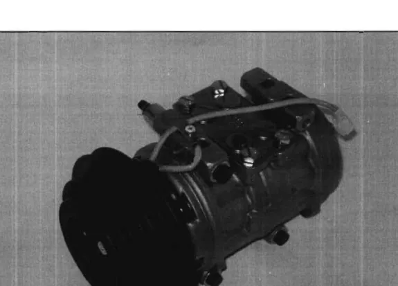
2.1.1.1 Compressor
Compressor (as shown in Figure 3) is commonly referred to as the heart of the system, which is usually powered by a belt driven pump that is fastened to the engine for compressing and transferring refrigerant gas. Typically, the air-conditioning system is split into two sides, a high pressure side (defined as discharge) and a low pressure side (defined as suction). Since the compressor is basically just a pump, it must have a suction side and a discharge side. The suction side draws in refrigerant gas from the outlet of the evaporator. Once the refrigerant is drawn into the suction side, it is compressed and then sent to the condenser.
Figure 3: Compressor and clutch.
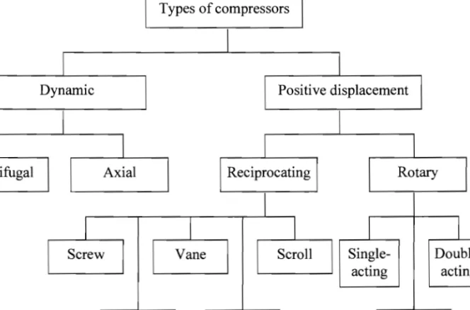
Figure 4 shows the types of compressors commonly used in conventional mr
conditioning system. Compressor generally can be divided into two primary categories; these categories are dynamic compressors and positive displacement compressors. Dynamic compressors are centrifugal and axial compressors, whereas positive displacement compressors are reciprocating and rotary compressors.
Types of compressors
Dynamic Positive displacement
Double
acting
Liquid ring Lobe Diaphragm
Figure 4: Types of compressors.
Centrifugal compressors
Centrifugal compressors are dynamic compressors. These compressors raise the pressure of the refrigerant by imparting velocity or dynamic energy and converting it to pressure energy
Axial-flow compressors
Generally, axial-flow compressors use a series of fan-like rotating rotor blades to progressively compress the gasflow. Stationary stator vanes (located downstream of each rotor) redirect the flow onto the next set of rotor blades. These type of compressors are normally used in high flow applications, such as medium to large gas turbine engines.
Reciprocating compressors
Reciprocating compressors use pistons driven by a crankshaft and can be either stationary or :J portable type. The operational of these compressors can be driven by electric motors or
r
internal combustion engines and can be single or multi-staged. Reciprocating compressors from 5 to 30 horsepower (hp) are commonly seen in automotive applications.Rotary screw compressors
Rotary screw compressors use two meshed rotating positive-displacement helical-screws to force the gas into a smaller space. It usually used for continuous operation in commercial and industrial applications. Besides, this type of compressor is also used for many automobile engine superchargers because it is easily matched to the induction capacity of a piston engine.
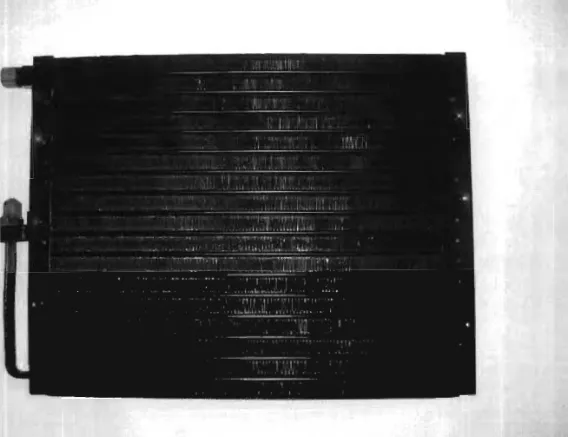
2.1.1.2 Condenser
The condenser (as shown in Figure 5) is the area in which heat dissipation occurs. In many cases, the condenser has the same appearance as the radiator as these two components have very similar functions. The condenser is generally designed to radiate heat from the air- conditioning system. It's usually mounted in front of the radiator. However in some cases, its location may differ due to aerodynamic improvements to the body of a vehicle. Besides, the condensers must have good air flow anytime the system is in operation. This is usually
accomplished by taking advantage of the existing engine's cooling fan on rear wheel drive vehicles. While on front wheel drive vehicles, condenser air flow is supplemented with one or more electric cooling fanes). When the hot compressed gasses from the compressor reach the inlet of the condenser, they are cooled off. As the gas cools, it condenses and exits at the bottom of the condenser as a high pressure liquid.
Figure 5: Condenser
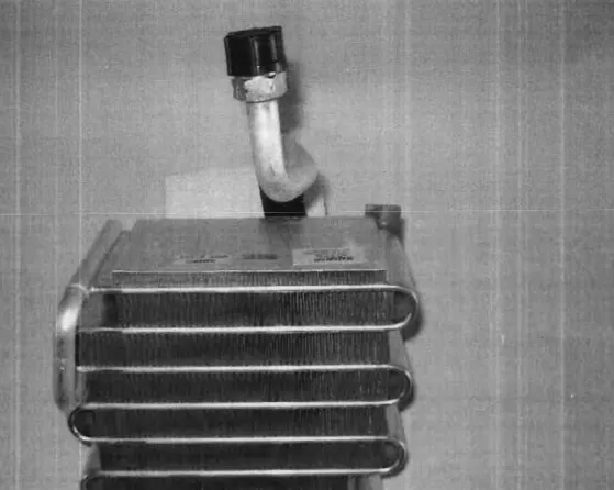
2.1.1.3 Evaporator
The evaporators (as shown in Figure 6) are located inside the automobile, which serves as the heat absorption component. Its functions are to remove heat from the automobile compartment and also dehumidification. The moisture contained in the air condenses on aluminum fins surface as the warmer air travels through the fins of the cooler evaporator coil.
In general, the ideal temperature of the evaporator is 32° Fahrenheit or 0° Celsius.
Refrigerant enters the bottom of the evaporator as a low pressure liquid. The warm air passing through the evaporator fins causes the refrigerant to boil because refrigerants have very low boiling points. As the refrigerant begins to boil, it can absorb large amounts of heat.
This heat is then carried off with the refrigerant to the outside of the automobile. Temperature and pressure regulating devices must be used to control the evaporator temperature in order to keep the low evaporator pressure and also to prevent evaporator from freezing.
Figure 6: Evaporator coil.
2.1.1.4 Pressure regulating devices
Controlling the evaporator temperature can be accomplished by controlling refrigerant pressure and flow into the evaporator. The most commonly used pressure regulators are orifice tube and thermal expansion valve.
Orifice tube
The orifice tube (as shown in Figure 7) is commonly used in most OM and Ford models. It is located in the inlet tube of the evaporator or somewhere between the outlet of the condenser and the inlet of the evaporator. This point can be found in a properly functioning system by locating the area between the outlet of the condenser and the inlet of the evaporator that suddenly makes the change from hot to cold. Most of the orifice tubes in use today measure approximately three inches in length and consist of a small brass tube, which surrounded by plastic and covered with a filter screen at each end.
Figure 7: Orifice tube.
Thermal expansion valve
Another common refrigerant regulator is the thermal expansion valve, as shown in Figure 8.
This type of valve can sense both temperature and pressure. It is also very efficient at
regulating refrigerant flow to the evaporator. This type of valve can be clogged with debris and may malfunction due to corrosion.
Figure 8: Thermal expansion valve.
2.1.1.5 Receiver-drier
Receiver-drier (as shown in Figure 9) is used on the high side of the systems that use a thermal expansion valve. The primary function of the receiver-drier is to separate gas and liquid. The secondary purpose is to remove moisture and filter out dirt. The receiver-drier usually has a sight glass in the top. This sight glass is often used to charge the system. Under normal operating conditions, vapor bubbles should not be visible in the sight glass. The use of the sight glass to charge the system is not recommended in R-134a systems because cloudiness and oil that has separated from the refrigerant can be mistaken as bubbles. This type of mistake can lead to a dangerous overcharged condition. There are variations of receiver-driers and several different desiccant materials, such as calcium chloride and silica
gel, are in use. The type of desiccant is usually identified through the sticker affixed on the receiver-drier.
Figure 9: Receiver-drier.
2.1.1.6 Accumulator
Accumulators are employed III the systems that accommodate an orifice tube to meter refrigerants flow into the evaporator. It is connected directly to the evaporator outlet and act to store excess liquid refrigerant because the introduction of liquid refrigerant into a compressor can do serious damage. Hence, the chief role of the accumulator is to isolate the compressor from any damaging liquid refrigerant. Besides, accumulators also help to remove debris and moisture from the cooling system.
2.1.1. 7 Other components
Figure 10 shows other components that could be utilized in vapor-compressiOn alr
conditioning system. These components are condenser fans, hoses, and aluminum pipe.
(a) Condenser fans
(b) Hoses and aluminum pipe
Figure 10: Condenser fans, hoses, and aluminum pipe.
2.1.2 Thermodynamics analysis o(vapor-compression cycle
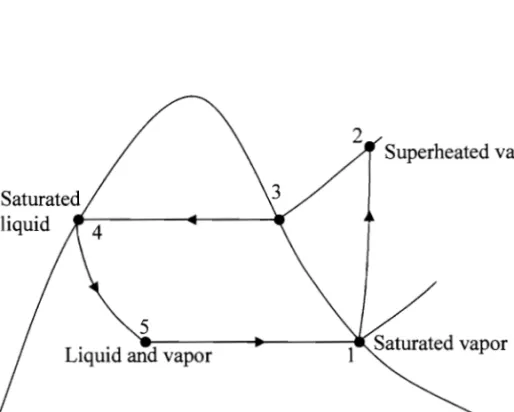
The vapor-compression refrigeration system uses a circulating liquid refrigerant as the medium to absorb and remove heat from the space to be cooled and subsequently rejects that heat elsewhere. The thermodinamic properties of the vapor-compression cycle can be analyzed on a temperature versus entropy diagram, as shown in Figure 11.
2 Superheated vapor
5
Liquid and vapor
Entropy
Figure 11: Temperature versus entropy diagram for a conventional vapor-compression cycle air-conditioning system.
In this cycle, a circulating refrigerant (such as Freon) enters the mechanical compressor as a vapor at point 1. From point 1 to point 2, the vapor is compressed and exits from the compressor as superheated vapor. Assuming there is no heat transfer to or from the
compressor, the mass and energy rate balance for a control volume enclosing the compressor is given as:
W com
- - - = h2 - hI (1)
m
where m is the mass flow rate of the refrigerant; W com / m is the rate of power input per unit mass of refrigerant flowing and h is the enthalpy.
" This superheated vapor travels through the condenser (from point 2 to point 3) to
removes the superheat by cooling the vapor. The vapor is then travels through the remainder of the condenser and is condensed into a saturated liquid (between point 3 and point 4) by removing the additional heat at constant pressure and temperature. The rate of heat transfer from the refrigerant per unit mass of refrigerant flowing for a control volume enclosing the condenser is given as:
(2) m
Between points 4 and 5, the saturated liquid refrigerant passes through the expansion valve and expands to the evaporator pressure. This process is usually modeled as throttling process for which:
(3)
It causes an adiabatic flash evaporation and auto-refrigeration of a portion of the liquid, which results in a mixture of liquid and vapor at a lower temperature and pressure (as shown at point 5). The cold liquid-vapor mixture then travels through the evaporator coil and
is completely vaporized by cooling the warm air being blown by a fan across the coil. The resulting saturated refrigerant vapor returns to the compressor inlet at point 1 to complete the thermodynamic cycle. The mass and energy rate balances reduce to give the rate of heat transfer per unit mass of refrigerant flowing for a control volume enclosing the evaporator is given by:
Qin ,
=
h - h 1 5 (4)m
i'
where Qin is referred to as the refrigeration capacity.r
In the vapor-compression system, the net power input is equal to the compressor power. Hence, the coefficient of performance (COP) of vapor-compression refrigeration system is given as:
,
/
Qinl m
COP
=
/ (5)Wenm/ m
2.2 Sorption Air-cooling Technologies
Sorption system can be classified as closed cycle and open cycle, as illustrated in Figure 12.
Closed cycles are referred to absorption and adsorption cycles, while open cycles are referred to desiccant cycle.
Sorption system
~ I
Closed cycle Open cycle
~ I ~
\VAdsorption cycle Absorption cycle Desiccant cycle
Figure 12: Sorption system
2.2.1 Adsorption cycle
An adsorption cycle for air-conditioning or refrigeration does not use any mechanical energy, but only heat energy. An adsorption unit usually consists of one or several adsorbers, a condenser, an evaporator and connected to the heat sources. The cycle is basically an intermittent because cold production is not continuous, where cold production proceeds only during part of the cycle. When there are two adsorbers in the unit, they can be operated out of phase and the cold production is a quasi-continuous. When all the energy required for heating the adsorber(s) is/are supplied by the heat source, the cycle is termed as single effect cycle.
When there are two adsorbers or more, double effect cycle can be processed. In double effect cycles some heat is internally recovered between the adsorbers, which enhances the cycle performance. Various type of adsorption cycles have been studied extensively by Wang (2001 a). Typically, some of the common adsorption cycles are basic cycle, mass recovery cycle, continuous heat recovery cycle, thermal wave cycle, cascade multi effect cycle, and hybrid heating and cooling cycle.
2.2.1.1 Basic adsorption cycle
Generally basic adsorption cycle can be well represented by using Clapeyron diagram, as shown in Figure 13. At point 1, the ideal adsorption cycle start with low pressure Ps and low temperature T\. The adsorbent-adsorbate inside the collector is then heated from point 1 to point 2 at higher pressure P3. Continue heating of the adsorbent-adsorbate from point 2 to point 3 will cause some adsorbate vapor to be desorbed from the collector and then condensed at point 4 (condenser). After that, the adsorbate in liquid form is flowed into the evaporator from point 4 to point 5 at lowest temperature T 5 and pressure Ps. Meanwhile, desorption process end when the adsorbent heated to the highest temperature at T4.
Decreasing in temperature to T6 will cause the collector pressure dropped to Ps. The evaporator is then connected to the collector, where adsorption of the adsorbate vapor occurs.
At the same time, the adsorbent is cooled from point 6 to point 1 and the cycle repeats again.
In P
4 2 3
Ts - liT
2.2.1.2 Mass recovery adsorption cycle
Mass recovery adsorption cycle is mostly operated with two adsorbent beds. At the end of each half cycle, one of the adsorber is hot and the other is cold. The high pressure inside the hot adsorber must be depressurized down to the evaporator pressure, while the cold adsorber in low pressure must be pressurized up to the condenser pressure. The pressurization
depressurization process can be achieved by transferring adsorbate vapor from the hot adsorber to the cold adsorber via a tube connected these adsorbers. This process is also called as an 'internal vapor recovery process'. Mass recovery adsorption process involves only mass transfer and thus the process is rapid. In order to obtain a 'double effect', mass recovery could be initiated followed by heat recovery.
2.2.1.3 Continuous heat recovery adsorption cycle
Semi-continuous heat recovery cycle is mostly worked with two adsorption beds. The heat from the ad sorber to be cooled will transfer to the adsorber to be heated; this includes sensible heat as well as the heat of adsorption. In order to attain higher COP, multi-beds adsorption system is implemented to get more heat recovery. However, the operation of system will be complicated. Wang (2001b) has investigated a quasi-continuous adsorption refrigeration system with heat recovery as shown in Figure 14. In this system, adsorber A is cooled and linked to the evaporator to realize adsorption refrigeration while adsorber B is heated and connected to the condenser. Refrigerant in the form of liquid will flow into the evaporator through a flow control valve. The system is operated out of phase and the go
between will be a short time for heat recovery process. Thermal fluid in the circuit is circulated between the adsorbers by using two pumps and the connection to the cooler and heater are blocked during this process.
Condenser
Evaporator
Heater
Adsorber A
Adsorber B
Cooler
Figure 14: Schematics diagram of the two-bed heat recovery adsorption refrigeration system.
2.2.1.4 Thermal wave cycle
Thermal wave cycle is an essential process to improve the heat regenerative ratio, where a large temperature gradient exists along the adsorption bed. In this system, heating and cooling of the adsorbent beds is achieved through a heat transfer fluid such as high temperature oil. The system consists of two heat exchangers and two adsorbent beds, which are connected in series to produce a semi-continuous process. The function of the heat exchanger and the adsorbent bed is to create a large surface area for heat transfer with a low
- -
..-...
... _ ...
Figure 15 showed a typical thermal wave cycle, which consists of two phases. During the first phase, the fluid will retrieve heat from Adsober A in hot condition. The fluid is further heated at the heat exchanger and then proceeds to heat Adsorber B, which is cold. As the heating of the Adsorber B is continues, refrigerant is desorbs and condensed in the condenser. Meanwhile, Adsorber A adsorbs gas from the evaporator which provides cooling effect. In the second phase, Adsorber A is heated and Adsorber B is cooled in a similar way until the original circumstances are reached by reversed the pump operation.
Adsorber
A Condenser
Adsorber
.,~ B
\ Evaporator
Figure 15: Schematic diagram of the thermal wave cycle.
Many researchers (Sun et at., 1997; Tierney, 2007) have been studied the thermal wave cycle, however, so far there is no report of a successful prototype adopting this cycle.
The performance of the thermal wave cycle is mediocre because the system depends on a relatively large number of parameters, such as the flow rate of the circulating fluid, the cycle time, the rates of various heat transfer processes, and the adsorber configuration.
2.2.1.5 Cascading cycle
In cascading cycle, desorption-condensation processes and evaporation-adsorption processes is operated at different temperature levels by using different working pairs. such as zeolite
water/activated carbon-methanol (Douss & Meunier, 1989), or zeolite-water/silica gel
water, etc. This cycle is usually applied when there exists a large temperature difference between the heat source/ambient and evaporator/refrigeration space. A high temperature heat source, such as boiler, is used to drive the high temperature stage adsorption refrigeration cycle. Meanwhile, the low temperature stage is driven by sensible heat and heat of adsorption obtained from high temperature stage.
2.2.2 Absorption cycle
Absorption cycle is a process that produced refrigeration effect through the use of fluids and some quantity of heat input, rather than electrical input as in the vapor compression cycle. In these systems, absorbent is used to circulate the refrigerant. Absorption machines are commercially available in the market for two basic configurations. The first configuration is for applications above O°C, which are mainly for air-conditioning purposes. This configuration usually uses lithium bromide as the absorbent and water as the refrigerant.
refrigerant and water as the absorbent. Previously, intennittent absorption cycle powered by solar energy was used to produce cooling effect due to the fact that solar energy is an intennittent heat source. With the evolvement of absorption cooling technologies, continuous solar absorption air-conditioning systems are the preferred choice. Table 2 stated the advantages and disadvantages of the absorption cooling system.
Table 2: Advantages and disadvantages of absorption cooling system.
Advantages Disadvantages
1. Require little maintenance. 1. COP is quite low.
2. The only moving part is pump and 2. Regeneration processes require high might be no moving part for a small temperature (~150oC).
system.
3. No auxiliary energy is requires for 3. Heat release to the ambient is quite high.
small system operation.
4. Low energy cost (for pump 4. The system is quite complicated, where employed in large system only). advanced knowledge for maintenance is
required.
2.2.3 Desiccant cycle
For desiccant systems, desiccants are used to remove water from the incoming air. By removing the moisture from air will decreased the amount of energy needed to cool the air and also increases the comfort level in the conditioned space. The most common used desiccant is silica gel, activated alumina and lithium chloride salt. Figure 16 showed an open- cycle desiccant cooling system operating in a re-circulation mode. This system takes air from the building and dehumidifies it with desiccant; the air is then cools by heat exchange and evaporative cools prior to re-entering the room. The desiccant must be regenerated by heat, which can be achieved by using solar energy with solar air collector or heated air that passed
through the dehumidifier. Table 3 showed the advantages and disadvantages of the desiccant cooling system.
OUTDOOR
Evaporative
1--...e.I Solar/gas 1---" 1 - - - _ _ . . EXHAUST
cooler 1--...e.I heater
ROOM
Cool Evaporative Hot
oist cooler ~--I Dry
Figure 16: An open solid desiccant cycle.
Table 3: Advantages and disadvantages of desiccant cooling system.
Advantages Disadvantages
l. This system is environmentally l. Moving part in the rotor wheel of the solid friendly because water is commonly desiccant system requires maintenance.
used as a working fluid.
2. Hard to achieve low temperature in the 2. Can be integrated with a ventilation humid region.
and heating system.
3. Desiccant can be easily contaminated.
3. Heat release to the surrounding is
quite low. 4. The overall system is quite big.
5. Dehumidifier is needed.
2.3 Principle of Adsorption
According to Ruthven (1984), adsorption (as shown in Figure 17) occurs at the surface interface of two phases, in which cohesive forces including electrostatic forces and hydrogen bonding, act between the molecules of all substances irrespective of their state of aggregation. The adsorbing phase is called as adsorbent, whereas the material concentrated at the surface of that phase is called as adsorbate. Adsorbent is the substrates that contain a lot of miniscule internal pores to produce a large surface area in order to increase the adsorption capacity. The process by which adsorbate removed from the adsorbent surface is called as desorption or regeneration.
o
Adsorbateo
o o
Figure 17: Adsorption process.
Adsorption is an exothermic process which accompanied by evolution of heat. The quantity of heat release during the adsorption process is largely depends on the latent heat and the bond energies. Adsorption normally is stronger than condensation to liquid phase. For instance, if an adsorbent and adsorbate in liquid form coexist separately in a closed vessel, transfer of the adsorbate to the adsorbent will happen in the form of vapor. As a result, the temperature of the liquid phase will becomes lower while the adsorbent temperature rises.
~.
Adsorption processes generally can be categorized into two types; namely physical adsorption and chemical adsorption. Physical adsorption (physisorption) refers to the type of adsorption in which the forces involved are intermolecular forces or Van der Waals forces.
Chemical adsorption, on the other hand, is the type of adsorption in which the forces involved are covalence or ionic forces between the adsorbing molecules and the adsorbent. Covalence or ionic bonding is usually greater than Van der Waals bonding and more heat is liberated when chemical adsorption occurred, thus the process of chemical adsorption is irreversible.
Adsorbent usually can be restored to original states by applying heat through a desorption process. In general, most of the adsorption processes applicable to the thermal system or cooling machine mainly involve physical adsorption. In this research work, a great attention was on physical adsorption that is more suitable for solar air-conditioning applications.
In physical adsorption process, the performance of the adsorbent is control by surface properties, for instance the surface area, size of granules, micro-pores
«
2 nm) and macro- pores (> 50 nm), crystals or in pellets. Adsorbents can be classified into two types; they are hydrophilic adsorbent and hydrophobic adsorbent. Hydrophilic or polar adsorbents, such as zeolites, silica gel and active alumina, have a special affinity to polar substances like water.A ~.
1 Hydrophobic adsorbents are non-polar; therefore they have more affinity to oils and gases than to water. Some examples of non-polar adsorbents include activated carbons, silicalites and polymer adsorbents.
2.3.1 Adsorption eqUilibrium
For a particular adsorbent/adsorbate system, adsorption equilibrium relation can be stated by using adsorption potential equation (Dubinin & Astakhov, 1971) as shown below:
l
(6)
Adsorption is usually described through isotherms, that is, functions which connect the amount of adsorbate on the adsorbent, with its pressure (if gas) or concentration (if liquid). Several theories have been proposed in order to describe the isotherms of an adsorption process, such as Henry's Law, Langmuir's approach, Gibb's theory and adsorption potential theory.
Henry's Law
This theory is only valid for an adsorption process on a uniform surface at adequately low concentrations. The formula for Henry's Law is:
e P
=
e kc (7)where e is the base of the natural logarithm (also called Euler's number) and its value is approximately 2.7182818, p is the partial pressure of the solute above the solution, c is the concentration of the solute in the solution and k is the Henry's Law constant.
Langmuir's approach
In 1916, Irving Langmuir has published a new isotherm for gases adsorbed on solids. This approach is based on the kinetic equilibrium and it is used to understand the adsorption process on a monolayer surface. It is based on four hypotheses, these hypotheses are:
1. the surface of the adsorbent is uniform where all the adsorption sites are equal, 2. all adsorption occurs through the same mechanism,
3. adsorbed molecules do not interact, and
r.
4. only a monolayer is formed at the maximum adsorption.
However, these hypotheses are seldom true because there are always imperfections on the surface, the mechanism is clearly not the same for the very first molecules as for the last to adsorb, adsorbed molecules are not necessarily inert and also more molecules can adsorb on the monolayer.
Gibb's theory
This theory is based on the perfect gas equation, where the adsorbate is treated in microscopic and bi-dimensional form.
Adsorption potential theory
This theory is a purely thermodynamic approach and it is suitable for adsorption in micro
porous substances. In order to analyze the adsorption process due to the presence of sub
critical vapors in the micro-pores solids, Dubinin and Astakhov (1971) have developed the semi-empirical DR equation as shown below:
(8)
The letter E in the above equation represents the interaction energy between the solid and adsorbing molecule. This equation is commonly used to describe the adsorption isotherms of sub-critical vapors in micro-porous solids such as activated carbon and zeolite.
Unfortunately, the DR equation does not describe well the equilibrium data when the degree
"
The equilibrium of adsorption for micro-porous material with surface heterogeneity iswell expressed by using DA (Dubinin-Astakhov) equation as shown below, where the exponent n describes the surface heterogeneity. This equation is sufficient for many engineering applications that used low-grade heat such as solar energy.
w
(9)2.3.2 Type of solid adsorbents
Solid adsorbents generally can be divided into two kind; namely hydrophilic and hydrophobic solid adsorbents. Some of the common solid adsorbents are as shown in Figure 18.
Solid adsorbents
,
!
J
Hydrophilic Hydrophobic
adsorbents adsorbents
I I I I I
Silica
gel Zeolites
I
ActivatedI
I
carbonMetal oxides
Metal hydrides
I
Activated Calcium alumina chloride
Figure 18: Type of solid adsorbents.
36
1
- - - -
...-~--...
2.3.2.1 Hydrophilic solid adsorbents
Hydrophilie, from the Greek (hydro) "water" and (phi lie ) "friendship", refer to a physical property of a molecule that can transiently bond with water through hydrogen bonding. This is thermodynamically favorable, which makes these molecules soluble in water and in other polar solvents. Some of the common hydrophilic adsorbents used in adsorption cooling system are silica gel, activated alumina, zeolites and calcium chloride.
Silica gel
r
Silica gel (Si02.xH20) is prepared from pure silica and retains chemically bonded with approximately 5% of water. Silica gel is normally used in applications under 200°C because it will lost its adsorption capacity if overheated. This substance is available in various pore sizes with the smaller pore size provides greater surface area per unit mass, which is typically 650 m2
/kg. Silica gel is widely used as a desiccant for dehumidication purposes as it has a large capacity for adsorbing water, especially at high vapour pressures. It is also used in the separation of gases and liquids. Silica gels with the pore sizes ranging from 2 nm to 3 nm (Type A) to 0.7 nm (Type B) are the most common used in commercial applications. Type A is specifically used for general drying and Type B used for relative humidities greater than
<
50%.
Activated alumina
Activated alumina is aluminium oxide in a porous form prepared by dehydration of aluminium hydrates (mostly Ah03.3H20) to about 6% moisture level. The pore sizes of activated alumina are ranging from 1.5 nm to 6.0 nm with surface area between 150 m2/kg
and 500 m2/kg. It is generally useful as a drying agent and also adsorbent for polar organic substances.
Zeolites
Zeolites are alumino silicate minerals, which are naturally occurring. Many types of synthetic zeolites have been developed for special applications, such as molecular sieves (using types 4A, SA, lOX and 13X which have been developed by the Linde Co. in U.S.A). In general, these substances have cavity volumes in the range of 0.05 to 0.30 cm3/g. Besides, they can be heated to about 500°C without damage their adsorption and regeneration properties. Type 4A (NaA) is used for drying and separation of hydrocarbon mixtures, while type SA (CaA) is used to separate paraffins and some cyclic hydrocarbons. Type lOX (CaX) and 13X (NaX) adsorb quite a wide range of adsorbates because of their larger diameter of inlet necks of their pores.
Calcium chloride
Calcium chloride is a very widely available adsorbent that remains solid until saturated. If saturated, it dissolves in water but can still be used as a low temperature liquid desiccant.
Typically, it has good potential for use as a solid chemical adsorbent for methanol and ethanol vapors.
2.3.2.2 Hydrophobic solid adsorbents
Hydrophobe, from the Greek (hydro) "water" and (phobos) "fear", in chemistry refer to a physical property of a molecule that is repelled from a mass of water. Hydrophobic molecules
j
I tend to be non-polar, thus prefer other neutral molecules and non-polar solvents.
f '
Hydrophobic molecules in water always cluster together. Some of the common used hydrophobic adsorbents are activated carbons, metal oxides and special developed porous metal hydrides.
Activated carbons
Activated carbon (also called as activated charcoal or activated coal) is a form of carbon that has been processed to make it extremely porous. Thus, activated carbon (as shown in Table 4) has a very large surface area available for adsorption or chemical reactions. In general, one gram of activated carbon has a surface area more than 500 m2 due to its high degree of microporosity. Normally, activated carbon is produced from carbonaceous source materials like nutshells, wood and coal.
Table 4: Total pore volume and surface area for some of the activated carbon (Ruthven, 1984).
Type of Activated Carbon Coconut shell
Bituminous coal Lignite coal f
Wood (Chemically activated)
\
Total Pore Volume (mL/g) 0.5 -0.6 0.6-0.7 0.9 - 1.0 1.4-1.8
Surface Area (m2/g) 1000 -1100 1000 - 1150
600 - 675 1200 - 1600
Activated carbons can be produced by physical reactivation and chemical reactivation processes. In physical reactivation process, the precursor is developed into activated carbons by using gases. This is generally done by using one or a combination of the following