PROJECTOR-BASED AUGMENTED REALITY FOR QUALITY INSPECTION OF
SCANNED OBJECTS
J. Kern, M. Weinmann, S. Wursthorn
Karlsruhe Institute of Technology (KIT), Institute of Photogrammetry and Remote Sensing (IPF), Karlsruhe, Germany (jens.kern, martin.weinmann, sven.wursthorn)@kit.edu
Commission II, WG II/4
KEY WORDS:Thematic mapping and monitoring, 3D, Augmented Reality, sensor and system calibration, projector-camera
ABSTRACT:
After scanning or reconstructing the geometry of objects, we need to inspect the result of our work. Are there any parts missing? Is every detail covered in the desired quality? We typically do this by looking at the resulting point clouds or meshes of our objects on-screen. What, if we could see the information directly visualized on the object itself? Augmented reality is the generic term for bringing virtual information into our real environment. In our paper, we show how we can project any 3D information like thematic visualizations or specific monitoring information with reference to our object onto the object’s surface itself, thus augmenting it with additional information. For small objects that could for instance be scanned in a laboratory, we propose a low-cost method involving a projector-camera system to solve this task. The user only needs a calibration board with coded fiducial markers to calibrate the system and to estimate the projector’s pose later on for projecting textures with information onto the object’s surface. Changes within the projected 3D information or of the projector’s pose will be applied in real-time. Our results clearly reveal that such a simple setup will deliver a good quality of the augmented information.
1. INTRODUCTION
With augmented reality (AR), our vision of real objects can be extended with additional computer generated information. If the virtual information is spatially registered to the real object in real-time, the user will be able to interact with spatial data in his natural environment and scale (Wursthorn et al., 2004). The augmentation can be achieved with the help of a head-mounted display (HMD, also called smart glasses or generally NED for near eye display (Hainich and Bimber, 2011) ) like Microsoft’s HoloLens (Microsoft, 2017) or a video-based solution by adding information to the video stream of a tablet’s back camera. With a video projector, a user does not need to wear a HMD or have to hold a tablet to view additional data. A group of users can jointly see the same projected information on an object with a sufficiently diffuse surface reflectance behavior. In (Ridel et al., 2014), it is proposed to highlight inscriptions on antique artifacts with projector-based augmented reality. The support of surgeries by projecting information on patients is addressed in (Nicolau et al., 2011; Lahanas et al., 2014; Kilgus et al., 2014).
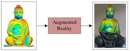
In this paper, we show how we use augmented reality techniques to project information on the surface of objects that fit approxi-mately into a cube of 1 m edge length to let one or more users naturally inspect this spatially registered information on the ob-ject itself. In this way, users can focus their work on the obob-ject instead of permanently changing views between the object and a display. For instance, the 3D information of color-coded differ-ences between two scanning results of a Buddha statue shown on the left side of Figure 1 can be projected directly onto the real ob-ject on the right side. The 3D information used for augmentation does not necessarily need to be static like in the above example.
One could project a point cloud resulting from a scanning task in real-time in order to give the user a direct feedback on regions on the object that still need to be scanned. The focus in this paper
Augmented Reality
Figure 1. Schematic representation of a projector-based aug-mented reality application. Some color coded 3D information related to an object (left) is directly projected onto the object it-self (right) to simplify an inspection task for the user.
is not on a distinct application but on the configuration, calibra-tion and registracalibra-tion of a low-cost projector system enabling aug-mentation with any 3D information, static or dynamic, of small objects.
The registration of object and projection is done with a combina-tion of a camera and an off-the-shelf projector and the use of a board with a pattern of coded targets. The working object is sim-ply put on the pattern board and registered once at the beginning of a session. The projector system itself is mounted on a move-able tripod to enmove-able a quick setup of different views. The pose of the projector system relative to the pattern board is computed in real-time. The main contributions of this paper are:
• A simple calibration method of the projector-camera system with a board of coded fiducial markers.
• The use of the calibration board for simple and real-time registration of object and projected information.
After briefly summarizing related work in the field of augmented reality in Section 2, we describe the proposed methodology for projector-based augmented reality in Section 3. Subsequently, in Section 4, we present the involved setup and we demonstrate its performance for the example of an indoor scene. The insights gained via our experiments are summarized in Section 5. Finally, in Section 6, we provide concluding remarks as well as sugges-tions for future work.
2. RELATED WORK
Research on augmented reality (AR) started with early works on display technology for virtual reality (Cruz-Neira et al., 1993) or head-mounted displays (Sutherland, 1968) before the terms augmented reality(Azuma, 1997) ormixed reality(Milgram and Kishino, 1994) have been defined.
The user’s vision can be augmented in different ways depen-dent on the technology, the application and the environment like prepared or unprepared indoor spaces or even outdoor spaces. With video-based AR, the environment is captured by a camera. Its image is shown on a screen fixed to the camera that can be augmented with computer-generated 3D models that are simply transformed into every camera frame. The camera’s inner and exterior orientation (its pose) have to be known at the moment the transformation takes place to fulfill the real-time constraint defined for AR (Azuma et al., 2001).
In AR, much of the research is focused on tracking the device’s pose in real-time with the help of one or more cameras. The simplest camera-based tracking method is marker-based with the typical planar square targets from projects like ARToolKit (Kato and Billinghurst, 1999; Abawi et al., 2004) or ArUco (Garrido-Jurado et al., 2014, 2016). If placing markers is not an option, nat-ural features like keypoints could be used (Comport et al., 2006; Klein and Murray, 2009). Typical smartphone or tablet hardware can do the processing of such system setups today. More sophisti-cated methods use 3D building models (Urban et al., 2013, 2016) or even textured city models for camera-based tracking within these models (Reitmayr and Drummond, 2006). Video-based augmented reality enables occlusions by virtual objects since the real environment is only visible through the display.
Modern HMDs like Microsoft’s HoloLens (Furlan, 2016) use four cameras in combination with a depth sensor to track the device within an unprepared environment and simultaneously create a sparse 3D model in a SLAM like manner. Environments are per-sistently stored between sessions and continuously updated. This enables the HoloLens to accurately determine its pose and ro-bustly place virtual objects, which Microsoft calls “holograms”, within the real environment. In order to enable occlusions with this technology, the HMD hardware has to be prepared for it (Gao et al., 2013). In a collaborative AR project, every participating person has to wear such a device. First, given the high price for the HoloLens or other HMDs, this will increase the costs for the project. Second, HMDs are still not comfortable enough for typ-ical working times (Schwerdtfeger et al., 2011).
Using tablets or smartphones instead of HMDs may reduce cost. But the drawback of these devices is that they have to by held by one hand while the other hand is used for interactions on the screen. This way, the user has to lay down the tablet for interac-tions with his real environment or the tablet has to be fixed some-where requiring users to always come back to see any augmented information on the tablet’s screen.
Projector-based AR, also called spatial AR (Bimber and Raskar, 2005), enables a group of users to see the same augmented in-formation. Bandyopadhyay et al. (2001) define the term “shader lamp” for projector-based textures. The AR setup can be prepared first without any action required by the actual users later on. The best usage scenario is an indoor space that could be specially pre-pared like surgery rooms (Nicolau et al., 2011; Lahanas et al., 2014; Kilgus et al., 2014), manufacturing workplaces (Otto et al., 2014; Sand et al., 2016) or exhibition rooms (Ridel et al., 2014). The geometry and texture of projection surfaces can be measured in advance or, with the help of depth sensors, in real-time (Hoang et al., 2017). Occlusions are not possible with projector-based augmented reality.
Table 1 gives an overview of the three different types for aug-mentation with a comparison of some characteristics like quality of perception, calibration or usability.
Typical projectors are made for flat uniformly colored surfaces with good reflectance capabilities. The geometry of more com-plex surfaces that differ from that flat model has to be known in order to correct the thereby resulting distortions. Pantuwong et al. (2016) use a projector in combination with a Microsoft Kinect depth camera to interactively augment the surface of sand in a sandbox with a color-coded height visualization and flowing wa-ter simulation. The surface of sand is ideal in this case because it has smooth edges. Every region of the sandbox can be measured by the depth camera with a nadir view and the sand’s texture is more or less homogeneous.
Many applications require a setup of more than one projector (Bimber and Raskar, 2005; Hainich and Bimber, 2011; Otto et al., 2014; Jones et al., 2014; Hoang et al., 2017) to increase the projected area or to cover an object with projections from several sides. Multi-projector setups are more complex for geometric calibration and need additional photometric correction at least in the overlapping areas (Brown et al., 2005; Hainich and Bimber, 2011).
Typical office projectors are not bright enough for outdoor usage at normal daylight conditions. Many of them are based on DLP (Digital Light Processing) or LCD technology. They have a nar-row depth of field because of the large apertures that are used to maximize the overall brightness. This causes problems for com-plex surfaces especially on surface parts that are outside the depth of field. Oyamada and Saito (2008) present a method for reducing the effect of defocus blur with a single projector-camera system. Laser projectors do not have these disadvantages because they op-erate with one laser beam that covers an area at a high frequency. They are able to project precise monochrome labels and signa-ture on surfaces. EXTEND3D (2017) provide such laser-based projector-camera systems for commercial industry applications.
Video-based See-through Projector-based
Device Smartphone, Tablet HMD, Smart Glasses DLP, LCD, LASER
Quality of perception display covers real environ-ment; enables occlusions
transparency of virtual ob-jects, like sunglasses
dependent on surface struc-ture and color
Calibration once once per session once
Number of users per device few single person few to many
Usability one hand to hold, both hands
for interactions
hands free, may be uncom-fortable on longer sessions
needs prepared environment
Outdoor capability dependent on display brightness only at night or with laser
projector
Table 1. Some characteristics for the three different types of augmentation: video-based, see-through and projector-based.
use a self-calibration approach with the help of the known geom-etry of an object or surface that is later used for projecting the information onto. Jones et al. (2014) use a setup of multiple pro-jectors, each in combination with a Microsoft Kinect. They use an automatic calibration process with the help of a projected code sequence observed by all units that yields dense correspondences in both 2D and 3D with the help of the depth images. After solv-ing the extrinsic parameters of each unit, a unified 3D model of the room is formed by combining the depth maps.
The use of depth sensors is common in AR projects because they provide 3D models of the near environment in real-time. This is the environment the user interacts with like placing virtual ob-jects on real tables or walls. The depth information enables occlu-sion of virtual objects by real objects which helps users to expe-rience precise spatial interaction of both virtual and real objects. Furthermore, depth sensors help to make egomotion tracking of the devices themselves more robust if combined with other sen-sors. For instance, the HoloLens HMD has a built-in depth sensor for tracking and mapping support and hand gesture recognition. Google’s Project Tango uses smartphones or tablets with a built-in depth sensor (Google Inc., 2017). There is even a small attach-able depth sensor called “Structure Sensor” for tattach-ablets availattach-able (Kakadiaris et al., 2016).
3. METHODOLOGY
Our augmented reality system consists of a rigid combination of an off-the-shelf color projector and a camera system. The camera is used for a simple marker-based pose estimation of the projec-tor relative to the 3D object and for calibration of the inner ori-entation (IO) of the projector. The projector restricts the system for indoor use. The system itself is mounted on a studio tripod with wheels that allow movements on the floor within the range of length of the cables used for data transfer and power supply to camera and projector. The inclination can be adjusted but has to be fixed with a locking screw. Most of the pose adjustments during a session will be the movements around the object and turn around the vertical axis in order to project information on different parts of the object.
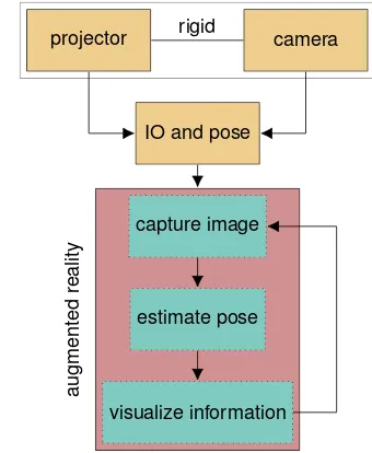
Since most off-the-shelf projectors have a lens that allows manual adjustment of focus or even zoom, the system needs a robust and automatic calibration procedure. Accordingly, calibration will be described first (Section 3.1). Afterwards, we will describe regis-tration and the steps needed for optimizing the rendering pipeline that allows us to project virtual 3D models onto the object’s sur-face (Section 3.2). A schematic overview of our system is pro-vided in Figure 2. Photometric corrections of the projections due
to the object’s varying texture or reflectance are not covered in this paper.
projector rigid camera
IO and pose
capture image
estimate pose
visualize information
augmented
reality
Figure 2. Flowchart of required steps to combine real and virtual world with a projector-based augmented reality application.
3.1 Calibration
To calibrate the projector-camera system, a marker-based method as presented in (Audet and Okutomi, 2009) is used. In general, the calibration of the interior orientation of the projector and the relative pose between projector and camera can be estimated us-ing standard camera calibration algorithms. One of the patterns is, as usual with many camera calibration techniques, printed on paper. The other is projected using the projector. The printed pattern is a chessboard-like arrangement of fiducial markers in which each square marker can be uniquely identified by different binary codes with the squared areas. We use the ArUco marker system specially optimized for pose estimation (Garrido-Jurado et al., 2014, 2016). This allows us to perform the calibration without requiring all markers to be visible at once. The projected pattern complements the empty spaces of the printed one with ArUco markers if they are overlaying properly. To facilitate the detection, the color of the projected pattern is inverted and has significantly smaller markers than the printed one. See the pic-ture of the calibration board on top of the flow chart in Figure 4. The projected white markers cover only a fraction of the board due to the limitation of the projector’s lens settings.
a common coordinate system. The scale of the printed pattern has to be known in order to perform a metric evaluation. Both patterns, the printed one and the projected one, need to have the same resolution or the scale between these patterns has to be well-known. Starting the calibration routine, the projected image is displayed as full-screen and has to lie mainly in the same area as the printed pattern. Both patterns are now superimposing in parts, so that a few transformation steps are required to solve this problem (see Figure 2).
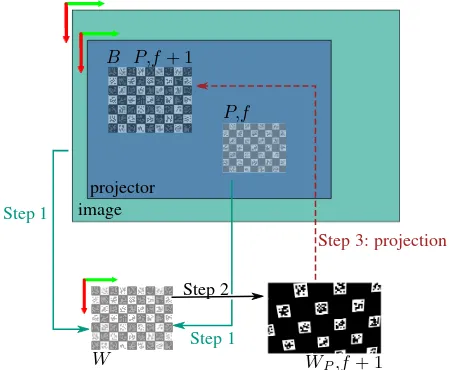
Figure 3. Use of a homography to warp the projected pattern. After applying the transformation, the projected pattern comple-ments the printed one.
First, the image to be projected is generated in a resolution four times larger than the resolution of the projector to decrease alias-ing effects while transformalias-ing the image.
Hereinafter, the common world target coordinates of the pro-jected and printed patterns (W) are∈R3(see Figure 3). Coordi-natesp∈R2which refer to printed components on the calibra-tion board are denoted with indexB and projected components with indexP. In the captured image at framefof the camera, the projected pointspP,f and the pointspB,fof the printed pattern on the board are detected.
The homographyHW
B is a perspective transformation model for planes which transforms the image points of the board to the im-age plane of the world coordinates. The Z-component of the world coordinates in the board can be omitted. The resulting points are calledpW ∈ R2. The homographyHPW transforms the image points of the projected pattern into the image plane of the world coordinates. Both homographies are calculated using a RANSAC-based method (see Step 1 in Figure 3). First, the cam-era image points of the printed markers are transformed to the target position in world coordinates:
pWB = HWB ·pB (1)
Then, the camera image points of the projected markers are trans-formed to the world coordinate system:
pWP = HWP ·pP (2)
In a further step, the previously projected pattern is warped so that the projected points are displayed at the desired positionpB,f+1 on the printed pattern of the next frame (f + 1, see Step 2 in
Figure 3):
pWP,f+1= HWP,f·H B
W·pWP,f (3) Since the image for projection is still in higher resolution, it has to be smoothed and scaled to the size of the projector resolution to reduce aliasing effects before it can be displayed.
Now the printed and projected markers are no longer superim-posed (see Step 3 in Figure 3) which allows a more accurate detection of the projected markers and images can be captured for calibration. To compute the calibration, all transformations made on the projected pattern have to be stored. The previously presented transformations are calculated and applied during the capturing of the calibration images. The calibration images and the corresponding stored transformations are required for the fol-lowing determination of the interior orientation of the projector and the relative pose between projector and camera. Figure 4 schematically shows the used calibration method of the projector-camera system. The interim results are highlighted in green (dot-ted) and implemented functions to estimate the calibration in red (dashed).
The calibration of a projector can be implemented by using cam-era calibration methods. For this, object points and corresponding image points of the projector are needed. The calibration of the relative pose between projector and camera is computed using a stereo camera calibration method. For this, object points and corresponding image points of the camera and the projector and their interior orientations are needed. The matrixV = HWP,f·HBW represents the stored homography applied to the projected image during capturing the calibration images. First, the printed mark-ers are detected in the image andHis estimated. The matrixH
is the renewed calculation of the homographyHWB, using opti-mized settings for the marker detection with subpixel accuracy of the edges. The visible projected markers are detected with subpixel accuracy, too. Because of the narrow depth of field of the projector, the defocused markers are bigger than the focused markers. To take this effect into account and minimize the in-fluence of inaccurate edge detection, the marker centers are used for calibration (Audet and Okutomi, 2009). The marker centers which are still distorted by the camera are used as image points of the camera. In a further step, the distortion of the camera is removed to get the object points (world coordinates) after apply-ing the transformation H. Now the marker centers in the im-age are only distorted by the projector. The imim-age points of the projector are calculated from the generated markers which are used for projection. For this purpose, the visible projected mark-ers are detected and the corresponding marker centmark-ers are deter-mined. The subsequently applied transformationV delivers the image points of the projector. To perform the calibration, the described steps have to be applied to every captured calibration image. The calibration itself is carried out using the OpenCV functioncalibrateCamera()based on methods from (Zhang, 2000) and (Bouguet, 2004). It resolves the interior orientation of the projector.
Now the interior orientations of the projector and the camera are known and the relative pose can be calibrated subsequently. For that, the OpenCV functionstereoCalibrate()can be called with the beforehand determined object points, image points of the camera and the projector. The interior orientations of the camera and the projector have to be handed over and labeled as fix while calling the function.
transformation H
image points of camera (marker centers, printed)
object points
stereoCalibrate()
IO camera
calibrateCamera()
image points of projector homography between
image points and world coordinates of the board (B)
undistort; transform with H
get center of visible markers; transform with V
Figure 4. Flowchart with the steps that are required to calibrate the relative pose between the camera and the projector.
inner orientations of both devices, the projector-camera system is ready for performing visual augmentations.
3.2 Augmentation
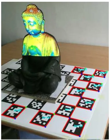
Figure 5 shows the projection of the rendered model onto the statue. The ArUco chessboard below the statue defines the world coordinate system in which the pose of the statue is known. It is the same pattern used for calibration. These markers are now used to estimate the pose of the projector-camera system in the world coordinate system. The virtual objects are then projected. The difference between the texture of the Buddha statue and the projected texture is clearly visible. Figure 2 schematically shows the procedure of a projector-based augmented reality application. At the start of the application, the software loads the required calibration parameters and settings. Now the actual augmented reality application can be executed. The first step of the AR loop is the capturing of a camera image and the detection of visible markers. The pose of the camera can be estimated using the known world coordinates of the markers and the image coordi-nates of the detected markers. The relative poseMPC between camera (C) and projector (P) is known from calibration. Using the actual poseMCof the camera, the poseMP of the projector
Figure 5. Live view with representation of the detected markers. Useful to control the field of view and the camera settings.
can be calculated as follows:
MP = MC·MPC (4)
with
M = "
R t 0 1 #
∈R4×4 , (5)
(a) Artifacts are clearly visible on the wall. (b) After applying the mask, the seam is removed.
Figure 6. Due to the remaining errors of calibration and pose estimation of the projector-camera system, colored artifacts can be observed (left image). These artifacts can be removed through applying a depth buffer-based mask (right image). The lower part is black due to the restricted area that the projector can cover.
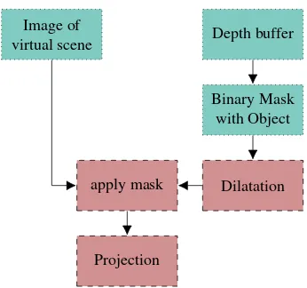
3.3 Depth buffer-based mask
Due to errors in the calibration of the interior orientation of the projector and camera, their relative pose and the pose estimation of the projector-camera system results in differences between de-sired and actual state of the projected information. The inac-curacy is especially visible at the edges of the real object. Un-wanted artifacts are pictured on surfaces behind the augmented object, which disturbs the subjective impression (see Figure 6a). These artifacts can be removed by applying a depth buffer-based mask. Figure 7 describes the developed method. First, the virtual objects are rendered and the resulting picture frame is buffered. While rendering the image, the depth buffer can be prompted as a grayscale image by using an OpenGL query. After binarization, the depth buffer delivers a mask which separates object informa-tion from the background. Now the mask is decreased with a morphological operator, so that it fades out the edge areas. After applying the mask, the projected image has no interfering seams (see Figure 6b). It can be observed that this method is simple and fast, however, it has a great influence on the subjective impression of the augmentation.
Image of
virtual scene Depth buffer
Binary Mask with Object
Dilatation apply mask
Projection
Figure 7. Process of applying a depth buffer-based mask on the projected image to remove unwanted seams.
4. EXPERIMENTAL RESULTS
We built a system which integrates OpenCV, ArUco and OSG to calibrate a projector-camera system and to test it in a specific application. For the setup we used the full HD sensor (1920× 1080) from the low-cost RGBD camera Intel RealSense R200 and a NEC V311W (1280×800color DLP) projector, with a footprint size of0.82 mm@2 mof a focused projected pixel. To test the system, a texture is projected onto a Buddha statue with a height of70 cm. The texture is a result of the rendering pipeline described in Section 3. With our system, we are able to project any 3D model onto real objects in this way.
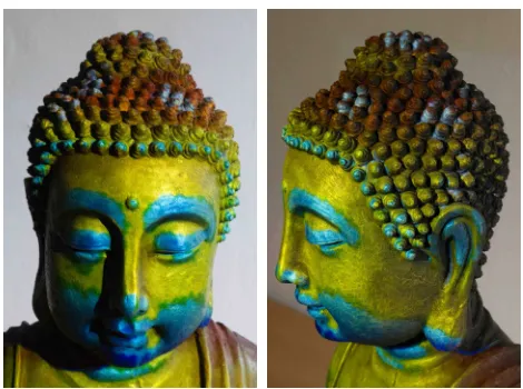
In Figure 1, the right side of the diagram shows how the pro-jector can cover the statue at a distance of approximately2 m. The lower part of the statue is black because it is outside the pro-jection area. In Figure 8, two close-ups of the resulting over-lay of our projector-based augmented reality system are shown. The overlaid texture is used for demonstration only. It visual-izes color-coded differences between two meshes resulting from different measurement techniques. The differences range from blue over green to red for−10 mmover0 mmto10 mm differ-ence between those two registered meshes. The referdiffer-ence model has been reconstructed from 86 scans created with a commer-cial scanning device (Breuckmann stereoSCAN3D-HE) based on fringe projection resulting in a dense and precise mesh. The other model has been reconstructed from 170 images with classic pho-togrammetric bundle adjustment and meshing.
The accuracy of the registration of the overlaid texture and the object can be seen in the detailed view in Figure 8(a). Overall, the configured system achieved a reprojection accuracy of known world coordinates better than4 mmin a hemisphere of4 m di-ameter. For the calibration, 15 different projector-camera views of the calibration board have been used.
(a) Detailed front view of the head. (b) Detailed side view of the head.
Figure 8. Detailed view of the projected color-coded representa-tion of a 3D comparison between the model of the statue and a point cloud. The detailed structures of the head allow to evaluate the quality of the projection.
5. DISCUSSION
We used two different low-cost RGBD cameras, the Intel Re-alSense R200 and the Microsoft Kinect V2 for testing purposes. For now, we did not use the depth sensing capabilities of these cameras in the methodology described in this paper. Even if the Kinect delivers images in higher quality, the RealSense is more suitable for the implemented application (Kern, 2016). In addi-tion, the RealSense is more compact and there are more possibili-ties to fix the camera to other objects. Another decisive advantage of using the RealSense is the ability to configure parameters like the exposure time, which is necessary for good calibration results.
The used off-the-shelf DLP office projector provides little lumi-nous intensity, so it can only be used in darkened rooms. In addi-tion, the footprint of unfocused pixels is bigger than the footprint of focused ones, so it is not suitable for high-precision applica-tions. Also the projection of text or numbers is not possible be-cause of the narrow depth of field. However, the projector is ide-ally suited for the application shown in this paper. The projector generates a color image from sequentially projected monochrome frames using a color wheel. In conjunction with rolling shutter cameras, there are some unpleasant effects, making it necessary to set the optimal camera and projector settings for best calibra-tion results.
The moveable tripod enables the user to quickly change the pro-jected view due to the registration with the marker board used for calibration. No other interference is needed by the user as long as there are enough markers within the camera’s sight. A successful pose estimation is clearly visible by the resulting projection onto the object. Because of the real-time tracking loop, the desired re-sult can be simply adjusted by the user by moving the tripod back and forth. If the freedom of movements with the projector-camera system on its tripod is too restricted by the length of cables, the laptop computer can be put on a rack directly fixed to the tripod.
Having all markers on just one plane is not the most robust so-lution for pose estimation. This was motivated by the fact that we wanted to keep the considered scenario as simple as possible for our first approach towards projector-based AR. If more ro-bustness and accuracy is required, the space covering the object
could be easily prepared with more markers on more planes, e.g. on the walls in a corner of a room.
6. CONCLUSIONS AND OUTLOOK
Even with our simple setup, small objects like our Buddha statue can be augmented with an off-the-shelf projector and a camera. Any kind of 3D information can be projected on known objects this way a long as this information is registered in 3D to the ob-ject. For the registration estimation of the projector-camera sys-tem, the flat calibration board with its coded fiducial markers is robust enough for a good quality. To compensate possible insuf-ficient calibration of intrinsic parameters of the projector’s lens, our depth buffer-based masking can remove unwanted seams.
Users are able to change the projected view by moving the tripod on its wheels around the object. The rendering process is contin-uously running in a loop adapting to all changes, be it the virtual 3D information or the projector’s pose.
Though we did not take photometric corrections due to varying properties of the object’s surface into account, the different colors of color-coded texture in our example projection are still distin-guishable. We started our project with less information in mind like the binary information to highlight “good” or “bad” regions, e.g. in terms of regions that have already been scanned or still need to be scanned or in terms of regions with a sufficient point density and regions with a point density below a given threshold.
In future work, using more than one projector would result in a more flexible system. This would for instance allow to com-pletely augment the statue with projected information. The user can then inspect the object from all directions without moving the system. Furthermore, different parts of the object can be augmented simultaneously because less parts are occluded, es-pecially for more complex objects like our test statue. Starting with two projectors, it would be necessary to take photometric corrections into account, at least for the overlapping regions.
In a laboratory, the projector could also be tracked by an installed (optical) tracking system. This could lead to more accurate re-sults but requires a large financial investment and different cali-bration methods. To project readable labels, a laser projector is indispensable. The actual system could be expanded by a laser projector to add this feature. The better way is to configure a sys-tem only using a color laser projector. This would solve problems like low luminous intensity and shallow depth of field.
References
Abawi, D. F., Bienwald, J. and Dorner, R., 2004. Accuracy in Opti-cal Tracking with Fiducial Markers: An Accuracy Function for
AR-ToolKit. In:Proceedings of the 3rd IEEE/ACM International
Sympo-sium on Mixed and Augmented Reality, ISMAR ’04, IEEE Computer Society, Washington, DC, USA, pp. 260–261.
Audet, S. and Okutomi, M., 2009. A user-friendly method to
geometri-cally calibrate projector-camera systems. In:Proceedings of the IEEE
Computer Society Conference on Computer Vision and Pattern Recog-nition Workshops, pp. 47–54.
Azuma, R., 1997. A survey of augmented reality. Presence:
Teleopera-tors and Virtual Environments6(4), pp. 355–385.
Azuma, R., Baillot, Y., Behringer, R., Feiner, S., Julier, S. and MacIntyre,
B., 2001. Recent advances in augmented reality. IEEE Computer
Bandyopadhyay, D., Raskar, R. and Fuchs, H., 2001. Dynamic shader
lamps: painting on movable objects. In:Proceedings of the IEEE and
ACM International Symposium on Augmented Reality, New York, NY, USA, pp. 207–216.
Bimber, O. and Raskar, R., 2005. Spatial Augmented Reality – Merging
Real and Virtual Worlds. A K Peters.
Bouguet, J.-Y., 2004. Camera Calibration Toolbox for Matlab. http:
//www.vision.caltech.edu/bouguetj/calib_doc/, visited in April 2017.
Brown, M., Majumder, A. and Yang, R., 2005. Camera-based calibration
techniques for seamless multiprojector displays. IEEE Transactions
on Visualization and Computer Graphics11(2), pp. 193–206.
Comport, A. I., Marchand, E., Pressigout, M. and Chaumette, F., 2006. Real-time markerless tracking for augmented reality: The virtual
vi-sual servoing framework. IEEE Transactions on Visualization and
Computer Graphics12(4), pp. 615–628.
Cruz-Neira, C., Sandin, D. J. and DeFanti, T. A., 1993. Surround-screen projection-based virtual reality: The design and implementation of the
cave. In: Proceedings of the 20th Annual Conference on Computer
Graphics and Interactive Techniques, SIGGRAPH ’93, ACM, New York, NY, USA, pp. 135–142.
EXTEND3D, 2017. Laser and video projection for the industry by
extend3d. http://www.extend3d.de/en/index.php, visited in
April 2017.
Furlan, R., 2016. The future of augmented reality: Hololens - Microsoft’s AR headset shines despite rough edges [Resources Tools and Toys].
IEEE Spectrum53(6), pp. 21–21.
Gao, C., Lin, Y. and Hua, H., 2013. Optical see-through head-mounted
display with occlusion capability. In: Proc. SPIE, Baltimore, MD,
USA, Vol. 8735, p. 87350F.
Garrido-Jurado, S., Mu˜noz-Salinas, R., Madrid-Cuevas, F. J. and Mar´ın-Jim´enez, M. J., 2014. Automatic generation and detection of highly
reliable fiducial markers under occlusion. Pattern Recognition47(6),
pp. 2280–2292.
Garrido-Jurado, S., Mu˜noz-Salinas, R., Madrid-Cuevas, F. J. and Medina-Carnicer, R., 2016. Generation of fiducial marker dictionaries using
Mixed Integer Linear Programming.Pattern Recognition51, pp. 481–
491.
Google Inc., 2017. Project Tango. https://www.google.com/atap/
projecttango/, visited in April 2017.
Hainich, R. R. and Bimber, O., 2011. Displays: Fundamentals &
Appli-cations. A K Peters LTD / CRC Press LLC.
Hoang, T., Reinoso, M., Joukhadar, Z., Vetere, F. and Kelly, D., 2017. Augmented studio: Projection mapping on moving body for
physio-therapy education. In: Proceedings of CHI 2017 – The ACM CHI
Conference on Human Factors in Computing Systems, Denver, CO, USA, pp. 1–12.
Jones, B., Sodhi, R., Murdock, M., Mehra, R., Benko, H., Wilson, A., Ofek, E., MacIntyre, B., Raghuvanshi, N. and Shapira, L., 2014. Roomalive: Magical experiences enabled by scalable, adaptive
projector-camera units. In:Proceedings of the 27th Annual ACM
Sym-posium on User Interface Software and Technology, UIST ’14, ACM, New York, NY, USA, pp. 637–644.
Kakadiaris, I. A., Islam, M. M., Xie, T., Nikou, C. and Lumsden, A. B.,
2016. iray: Mobile ar using structure sensor. In:Proceedings of the
2016 IEEE International Symposium on Mixed and Augmented Reality (ISMAR-Adjunct), Merida, Mexico, pp. 127–128.
Kato, H. and Billinghurst, M., 1999. Marker tracking and HMD cali-bration for a video-based augmented reality conferencing system. In:
Proceedings of the 2nd International Workshop on Augmented Reality (IWAR 99), San Francisco, CA, USA, pp. 85–94.
Kern, J., 2016. Entwicklung eines Projektor-basierten
Augmented-Reality-Systems. Master Thesis, Institute of Photogrammetry and Re-mote Sensing, Karlsruhe Institute of Technology.
Kilgus, T., Heim, E., Haase, S., Pr¨ufer, S., M¨uller, M., Seitel, A., Fangerau, M., Wiebe, T., Iszatt, J., Schlemmer, H.-P., Hornegger, J., Yen, K. and Maier-Hein, L., 2014. Mobile markerless augmented
re-ality and its application in forensic medicine.International Journal of
Computer Assisted Radiology and Surgery10(5), pp. 573–586.
Klein, G. and Murray, D., 2009. Parallel tracking and mapping on a
cam-era phone. In:Proceedings of the IEEE International Symposium on
Mixed and Augmented Reality - Arts, Media and Humanities.
ISMAR-AMH, Orlando, FL, USA, pp. 83–86.
Lahanas, V., Loukas, C., Smailis, N. and Georgiou, E., 2014. A novel augmented reality simulator for skills assessment in minimal invasive
surgery.Surgical Endoscopy29(8), pp. 2224–2234.
Microsoft, 2017. Microsoft HoloLens: a new way to see your
world. https://www.microsoft.com/microsoft-hololens/
en-us/hardware, visited in April 2017.
Milgram, P. and Kishino, F., 1994. A taxonomy of mixed reality
vi-sual displays.IEICE Transactions on Information SystemsE77-D(12),
pp. 1321–1329.
Nicolau, S., Soler, L., Mutter, D. and Marescaux, J., 2011. Augmented
reality in laparoscopic surgical oncology. Surgical Oncology20(3),
pp. 189–201.
OSG Community, 2016. OpenSceneGraph. http://trac.
openscenegraph.org/projects/osg/, visited in April 2017.
Otto, M., Prieur, M. and Rukzio, E., 2014. Using scalable, interactive
floor projection for production planning scenario. In:Proceedings of
the Ninth ACM International Conference on Interactive Tabletops and Surfaces, ITS ’14, ACM, New York, NY, USA, pp. 363–368.
Oyamada, Y. and Saito, H., 2008. Defocus Blur Correcting
Projector-Camera System. Springer, Berlin, Heidelberg, pp. 453–464.
Pantuwong, N., Chutchomchuen, N. and Wacharawisoot, P., 2016. Inter-active topography simulation sandbox for geography learning course. In: Proceedings of the 2016 8th International Conference on Infor-mation Technology and Electrical Engineering (ICITEE), Yogyakarta, Indonesia, pp. 1–4.
Reitmayr, G. and Drummond, T., 2006. Going out: Robust model-based
tracking for outdoor augmented reality. In:Proceedings of the
Inter-national Symposium on Mixed and Augmented Reality (ISMAR), Santa Barbara, CA, USA.
Resch, C., Keitler, P. and Klinker, G., 2016. Sticky projections – a
model-based approach to interactive shader lamps tracking. IEEE
Transac-tions on Visualization and Computer Graphics22(3), pp. 1291–1301.
Ridel, B., Reuter, P., Laviole, J., Mellado, N., Couture, N. and Granier, X., 2014. The Revealing Flashlight: Interactive Spatial Augmented
Reality for Detail Exploration of Cultural Heritage Artifacts.Journal
on Computing and Cultural Heritage7(2), pp. 6:1–6:18.
Sand, O., B¨uttner, S., Paelke, V. and R¨ocker, C., 2016.smARt.Assembly –
Projection-Based Augmented Reality for Supporting Assembly
Work-ers. Springer International Publishing, Cham, pp. 643–652.
Schwerdtfeger, B., Reif, R., G¨unthner, W. A. and Klinker, G., 2011. Pick-by-vision: there is something to pick at the end of the augmented tun-nel.Virtual Reality15(2), pp. 213–223.
Sutherland, I. E., 1968. A head-mounted three-dimensional display. In:
Proceedings of the AFIPS Fall Joint Computer Conference, Vol. 33, pp. 757–764.
Urban, S., Leitloff, J., Wursthorn, S. and Hinz, S., 2013. Self-localization of a multi-fisheye camera based augmented reality system in
texture-less 3d building models. In: ISPRS Annals of the Photogrammetry,
Remote Sensing and Spatial Information Sciences, Antalya, Turkey, Vol. II-3/W2, pp. 43–48.
Urban, S., Wursthorn, S., Leitloff, J. and Hinz, S., 2016. MultiCol bun-dle adjustment: A generic method for pose estimation, simultaneous self-calibration and reconstruction for arbitrary multi-camera systems.
International Journal of Computer Vision121(2), pp. 234–252.
Wursthorn, S., Coelho, A. H. and Staub, G., 2004. Applications for mixed
reality. In: The International Archives of the Photogrammetry,
Re-mote Sensing and Spatial Information Sciences, Istanbul, Turkey, Vol. XXXV-B3, pp. 1049–1054.
Yang, L., Normand, J. M. and Moreau, G., 2016. Practical and precise
projector-camera calibration. In: Proceedings of the 2016 IEEE
In-ternational Symposium on Mixed and Augmented Reality (ISMAR), Merida, Mexico, pp. 63–70.
Zhang, Z., 2000. A flexible new technique for camera calibration.IEEE