Q45U Discrete Output, 12-24 V DC
Range Temperature Compensation Connection Output Type Response Time Models 100 mm to 1.4 m No 2 m Bipolar NPN/PNP Programmable for 20, 40, 160 or 640 ms Q45UBB63DA5-pin Mini QD Q45UBB63DAQ
5-pin Euro QD Q45UBB63DAQ6
100 mm to 1.4 m Yes 2 m Bipolar NPN/PNP Programmable for 20, 40, 160 or 640 ms Q45UBB63DAC
5-pin Mini QD Q45UBB63DACQ
5-pin Euro QD Q45UBB63DACQ6
250 mm to 3 m† Yes 2 m Bipolar NPN/PNP Programmable for 40, 80, 320 or 1280 ms Q45UBB63BC
5-pin Mini QD Q45UBB63BCQ
5-pin Euro QD Q45UBB63BCQ6
Q45U Analog Output, 15-24 V DC
Range Temperature Compensation Connection Output Type Response Time Models 100 mm to 1.4 m Yes 2 m Selectable 0 to 10 V dc or 4 to 20 mA Adjustable from 40 to 1280 ms Q45ULIU64ACR
5-pin Mini QD Q45ULIU64ACRQ
5-pin Euro QD Q45ULIU64ACRQ6
250 mm to 3 m† Yes 2 m Selectable 0 to 10 V dc or 4 to 20 mA Adjustable from 80 to 2560 ms Q45ULIU64BCR
5-pin Mini QD Q45ULIU64BCRQ
5-pin Euro QD Q45ULIU64BCRQ6
Connection options: A model with a QD requires a mating cordset. For 9 m cable, add suffix W/30 to the 2 m model number (example, Q45UBB63DA W/30).
† The far limit may be extended as far as 3.9 m for good acoustical targets–hard surfaces with area greater than 100 cm2.
44.5 mm 54.1 mm 87.6 mm 30.0 mm 44.5 mm 79.4 mm 87.6 mm 30.0 mm
• The Q45U accepts programming storage cards for fast, easy sensing parameter changes with ranges up to 3 m • Bipolar discrete models have switches for ON/OFF presence
detection and HIGH/LOW level control
• In ON/OFF mode, bipolar discrete models detect when the target is within the set range or when it is outside the range • In HIGH/LOW mode, bipolar discrete models detect when
the target is outside the configured range, for fill level control, web tensioning control and similar applications
• Response time is programmed with switches in discrete models and with a potentiometer in analog models • Push-button and remote TEACH-mode programming with
an external switch, computer or controller for added security and convenience
Versatile Ultrasonic Sensors
Q45U Specifications
Sensing Range “A” suffix: Near limit: 100 mm min. (239 kHz) “B” suffix: Near limit: 250 mm min. (128 kHz)
“A” suffix: Far limit: 1.4 m max. (239 kHz) “B” suffix: Far limit: 3.0 m max. (128 kHz)
NOTE: The far limit may be extended on long range units, as far as 3.9 m for good acoustical targets (hard surfaces with area greater than 100 cm2)
Supply Voltage and Current Discrete: 12 to 24 V dc (10% max. ripple); 100 mA (exclusive of load) Analog: 15 to 24 V dc (10% max. ripple); 100 mA (exclusive of load)
Supply Protection Circuitry Protected against reverse polarity and transient voltages
Output Protection Circuitry Protected against false pulse on power-up and continuous overload or short-circuit of outputs
Output Configuration Discrete: Bipolar: One current sourcing (PNP) and one current sinking (NPN) open collector transistor
Analog: One voltage sourcing and one current sourcing; one or the other output is enabled by internal programming switch #2
Output Ratings Discrete: 150 mA max. (each)
OFF-state leakage current: less than 25 µA at 24 V dc ON-state saturation voltage: less than 1.5 V at 10 mA;
less than 2.0 V at 150 mA
Analog:
Voltage sourcing: 0 to 10 V dc, 10 mA max. Current sourcing: 4 to 20 mA, 1 to 500 Ω impedance Performance Specifications “A” suffix “B” suffix
Analog resolution or
discrete repeatability: ± 0.1% of sensing distance (± 0.25 mm min.) ± 0.1% of sensing distance (± 0.5 mm min.)
Analog Linearity: 1% of full scale 1% of full scale
Temperature effect: 0.05% of sensing distance/ °C with temp. comp. 0.05% of sensing distance/ °C 0.2% of sensing distance/ °C without temp. comp.
Min. window size: 10 mm 25 mm Hysteresis (discrete output): 5 mm 10 mm
Adjustments The following may be selected by a 4-position DIP switch.
Discrete: Switch 1: Output normally open/normally closed (pump in/pump out) Switch 2: High/Low level control mode or on/off presence sensing mode Switch 3 & 4: Response speed selection (digital filter)
Analog: Switch 1: Output slope positive or output slope negative Switch 2: Current output mode or voltage output mode Switch 3: Loss of echo min/max mode or loss of echo Hold Mode Switch 4: Loss of echo min/max default output value
Indicators Discrete: Three status LEDs:
Solid Green: power ON Flashing Green: output overloaded
Yellow: outputs are conducting (Yellow LED also indicates programming status during setup mode) Red: indicates relative strength of received echo
Analog: Three status LEDs:
Green: power ON Flashing Green: current output fault (4-20 mA current path to ground is open)
Yellow: target is sensed within the window limits (Yellow LED also indicates programming status during setup mode) Red flashing: indicates relative strength of received echo
5-segment moving dot LED indicates the position of the target within the sensing window. See data sheet for detailed information.
Construction Molded PBT polyester thermoplastic polyester housing, o-ring sealed transparent acrylic top cover, and stainless steel hardware.
Q45U sensors are designed to withstand 1200 psi washdown. The base of cabled models has a ½"-14NPS internal conduit thread.
Environmental Rating Leakproof design is rated IEC IP67; NEMA 6P
Operating Conditions Temperature: -25 to +70 °C Relative humidity: 100%
Vibration and
Mechanical Shock All models meet Mil. Std. 202F requirements. Method 201A (Vibration: 10 to 60Hz max., double amplitude 0.06", maximum acceleration 10G). Method 213B conditions H & I (Shock: 75G with unit operating; 100G for non-operation). Also meets IEC 947-5-2 requirements: 30G, 11 milliseconds duration, half sine wave.
Application Notes “A” suffix: Min. target size: 10 x 10 mm aluminum plate at 500 mm 35 x 35 mm aluminum plate at 1.4 m
“B” suffix: Min. target size: 50 x 50 mm aluminum plate at 3 m
Discrete: Enable/Disable; Connect yellow wire to +5 to 24 V dc to enable sensor and 0 to +2 V dc to disable sensor. When the sensor is disabled, the last output state is held until the sensor is re-enabled. The wire must be held to the appropriate voltage for at least 40 milliseconds for the sensor to enable or disable.
Certifications
SMB30A SMB30MM SMB30SC
Additional bracket information is available See page 722
5-Pin Euro-Style with Shield
Straight connector models listed; for right-angle, add RA to the end of the model number (example, MQDEC2-506RA) MQDEC2-506 2 m (6.5') MQDEC2-515 5 m (15') MQDEC2-530 9 m (30') 5-Pin Mini-Style with Shield
Straight connector models only MBCC2-506 2 m (6.5') MBCC2-515 5 m (15') MBCC2-530 9 m (30')
Additional cordset information is available See page 758
Q45UR Discrete Output, 12-24 V DC
Sensor Range Controller Connection ControllerOutput Kit Models Kit Includes: Controller & Sensor
50 to 250 mm 2 m Bipolar NPN/PNP Q45UR3BA63CK Q45UR3BA63C M18C2.0 Stainless Steel Barrel
5-pin Mini QD Q45UR3BA63CQK Q45UR3BA63CQ
5-pin Euro QD Q45UR3BA63CQ6K Q45UR3BA63CQ6
50 to 250 mm 2 m Bipolar NPN/PNP Q45UR3BA63CKQ Q45UR3BA63C Q13C2.0 Flat-Pak
5-pin Mini QD Q45UR3BA63CQKQ Q45UR3BA63CQ
5-pin Euro QD Q45UR3BA63CQ6KQ Q45UR3BA63CQ6
50 to 250 mm 2 m Bipolar NPN/PNP Q45UR3BA63CKS Q45UR3BA63C S18C2.0 Molded Barrel
5-pin Mini QD Q45UR3BA63CQKS Q45UR3BA63CQ
5-pin Euro QD Q45UR3BA63CQ6KS Q45UR3BA63CQ6
Q45UR Analog Output, 15-24 V DC
Sensor Range
Controller Cable
Controller
Output Kit Models Kit Includes: Controller & Sensor
50 to 250 mm 2 m Selectable 0 to 10 V dc or 4 to 20 mA Q45UR3LIU64CK Q45UR3LIU64C M18C2.0 Stainless Steel Barrel
5-pin Mini QD Q45UR3LIU64CQK Q45UR3LIU64CQ
5-pin Euro QD Q45UR3LIU64CQ6K Q45UR3LIU64CQ6
50 to 250 mm
2 m Q45UR3LIU64CKQ Q45UR3LIU64C
Q13C2.0 Flat-Pak
5-pin Mini QD Q45UR3LIU64CQKQ Q45UR3LIU64CQ
5-pin Euro QD Q45UR3LIU64CQ6KQ Q45UR3LIU64CQ6
50 to 250 mm
2 m Q45UR3LIU64CKS Q45UR3LIU64C
S18C2.0 Molded Barrel
5-pin Mini QD Q45UR3LIU64CQKS Q45UR3LIU64CQ
5-pin Euro QD Q45UR3LIU64CQ6KS Q45UR3LIU64CQ6
Connection options: A model with a QD requires a mating cordset. For 9 m cable, add suffix W/30 to the 2 m model number (example, Q45UR3BA63CK W/30). 44.5 mm
61.7 mm
87.6 mm
• Q45 housing with an available plastic or a stainless steel 18 mm threaded barrel sensing head or an ultra-compact plastic Flat-Pak sensing head
• The Q45UR has sensing ranges up to 250 mm • Resolution/repeatability +/- 0.2% of sensing distance
• Analog models feature a selectable positive or negative output slope • Environmental rating is IEC IP65 and NEMA 4
• Push-button and remote TEACH-mode programming with an external switch, computer or controller for added security and convenience
Remote Transducer Ultrasonic Sensors
Q45UR High-Gain Controllers
Version Model
Discrete 63060 Q45UR3BA63CQ6-63060
Analog 63667 Q45UR3LIU64CQ6-63667
NOTE: Special High-Gain controllers are available for small object detection. Contact factory for more information.
Q45UR Remote Sensors Specifications
Supply Voltage and Current Discrete: 12 to 24 V dc (10% max. ripple); 100 mA (exclusive of load) Analog: 15 to 24 V dc (10% max. ripple); 100 mA (exclusive of load)
Ultrasonic Frequency 400 kHz
Supply Protection Circuitry Protected against reverse polarity and transient voltages
Output Protection Circuitry Both outputs are protected against continuous overload and short circuit
Output Rating Discrete: 150 mA max. (each output)
OFF-state leakage current: less than 25 µA at 24 V dc ON-state saturation voltage: less than 1.5 V at 10 mA;
Analog: Voltage sourcing: 0 to 10 V dc, 10 mA max.
Current sourcing: 4 to 20 mA, 1 to 500 Ω impedance
Output Configuration Discrete: Bipolar: |One current sourcing (PNP) and one current sinking
(NPN) open collector transistor Analog: One voltage sourcing and one current sourcing; one or the other output is enabled by internal programming switch #2
Performance Specifications Discrete: Response Speed: 40 or 160 ms (switch selectable)
Repeatability*: ±0.2% of measured distance
Temperature stability: ±0.03% of the window limit positions per °C from 0 to 50 °C, (±0.05% per °C over remainder of operating temperature range)
Sensing window width: 5 to 200 mm, when independent near and far limits are taught; 1, 2, 3, or 4 mm (switch selectable), when a sensing distance set point is taught
Hysteresis: 0.5 mm Ultrasonic beam angle: ±3.5˚
Analog: Response Speed: 10 to 320 ms (2 to 64 cycles) selectable Resolution*: 0.2% of sensing distance at 320 ms response,
0.4% of sensing distance a 10 ms response Linearity*: 1% of full scale
Temperature stability: ±0.03% of sensing distance per °C from 0 to 50 °C, (±0.05% per °C over remainder of operating temperature)
Ultrasonic beam angle: ±3.5°
* Repeatability and analog resolution and linearity are specified using a 50 x 50 mm aluminum plate at 22° C under fixed sensing conditions (Analog: using the 4 to 20 mA output @ 15 V dc)
Adjustments Discrete: The following may be selected by a 4-position DIP switch
Switch 1: Output normally open (output is energized when
target is within sensing window limits), or normally closed (output is energized when target is outside sensing window limits)
Switches 2 & 3: Sensing window size (1, 2, 3 or 4 mm) Switch 4: Response speed selection
(40 or 160 milliseconds)
Analog: Push-button TEACH-mode programming of window limits. The following may be selected by a 4-position DIP switch located on top of the controller, beneath a transparent o-ring sealed acrylic cover and beneath the black inner cover. Switch 1: Output slope: output value increases or decreases
with distance
Switch 2: Output mode: current output or voltage output Switches 3 & 4: Response to loss of echo
Response Speed Adjustment: Single-turn potentiometer
selects six response values from 10 to 320 milliseconds
Indicators Discrete: Three status LEDs:
Green: Power ON
Yellow: Output are conducting (Yellow also indicates programming status during setup)
Red: Relative strength of received echo
5-segment moving dot LED indicates the position of the target within the sensing window
Analog: Three status LEDs: Solid Green: Power ON
Flashing Green: current output fault (4-20 mA current path to ground is open)
Yellow: Target is sensed within the window limits (Yellow LED also indicates programming status during setup mode) Red: Relative strength of received echo
5-segment moving dot LED indicates the position of the target within the sensing window (See data sheet for detailed information)
Construction Controller: Molded thermoplastic polyester housing, o-ring sealed transparent acrylic top cover, and stainless steel hardware
Sensors: M18C2.0: Stainless steel M18 threaded barrel housing and jam nuts, polyetherimide front cover, ceramic transducer, polyurethane rear cover
S18C2.0: Thermoplastic polyester S18 threaded barrel housing and jam nuts, polyetherimide front cover, ceramic transducer, polyurethane rear cover
Q13C2.0: Molded 30% glass reinforced thermoplastic polyester housing, ceramic transducer, fully epoxy-encapsulated
Environmental Rating Controller: IEC IP67; NEMA 6P Sensor: IEC IP65; NEMA 4
Operating Conditions Controller and sensor: -25 to +70 °C Relative humidity: 85% (non-condensing)
Vibration and
Mechanical Shock All models meet Mil. Std. 202F requirements. Method 201A Vibration: 10 to 60Hz max., double amplitude 0.06" (maximum acceleration 10G). Method 213B conditions H & I (Shock: 75G with unit operating; 100G for non-operation). Also meets IEC 947-5-2 requirements: 30G, 11 milliseconds duration, half sine wave.
Certifications
SMB30A SMB30MM SMB30SC
Additional bracket information is available See page 722
5-Pin Euro-Style with Shield
Straight connector models listed; for right-angle, add RA to the end of the model number (example, MQDEC2-506RA) MQDEC2-506 2 m (6.5') MQDEC2-515 5 m (15') MQDEC2-530 9 m (30') 5-Pin Mini-Style with Shield
Straight connector models only MBCC2-506 2 m (6.5') MBCC2-512 4 m (12') MBCC2-530 9 m (30')
Additional cordset information is available See page 758
Datasheet
Piezoelectric analog proximity mode sensors with push-button or remote programming of sensing window limits
• Ultrasonic proximity detection from 100 mm to 1400 mm (4 in to 55 in) • Push-button TEACH-mode programming of sensing window limits • Digital filtering for exceptional immunity to electrical and acoustic noise • 15 to 24 V dc operation
• Selectable 0 to 10 V dc voltage sourcing or 4 to 20 mA current sourcing analog outputs
• Selectable output slope: positive or negative with increasing target distance • Wide operating temperature range of –25 °C to +70 °C (–13 °F to +158 °F); all
models include temperature compensation
• Rugged design for use in demanding sensing environments; rated IEC IP67, NEMA 6P
• Choose models with an integral unterminated 2 m (6.5 ft) or 9 m (30 ft) cable, or with a Mini-style or M12/Euro-style quick-disconnect connection
• Input for remote TEACH-mode programming of window limits
Models Cable 1 Output Type Response Time Q45ULIU64ACR 2 m (6.5 ft)
Selectable 0 to 10 V dc or 4 to 20 mA sourcing
Adjustable from 40 milliseconds to 1.28 seconds
Q45ULIU64ACRQ 5-pin Mini-style quickdisconnect
Q45ULIU64ACRQ6 5-pin M12/Euro-style quickdisconnect
WARNING: Not To Be Used for Personnel Protection
Never use this device as a sensing device for personnel protection. Doing so could lead to serious injury or death. This device does not include the self-checking redundant circuitry necessary to allow its use in personnel safety applications. A sensor failure or malfunction can cause either an energized or de-energized sensor output condition.
Temperature Compensation
All models listed above feature temperature compensation. An increase in air temperature shifts both sensing window limits closer to the sensor. Conversely, a decrease in air temperature shifts both limits further away from the sensor. The shift is approximately 3.5% of the limit distance for a 20 °C change in temperature.
Temperature compensated models maintain the position of both sensing window limits to within 1% of each limit distance over the 0 °C to +50 °C (+32 °F to +122 °F) range, and to within 2.5% over the full operating range of –25 °C to +70 °C (–13 °F to +158 °F).
1 To order the 9 m (30 ft) cable models, add the suffix "W/30" to the cabled model number. For example, Q45ULIU64ACR W/30. Models with a quick disconnect (QD) connector require a mating cable.
Q45U Ultrasonic Sensors with Analog Outputs
(Short Range)
Overview
Limits N 1 2 3 4 5 3 4 5 1 2 7 Resp. Speed + – 6Figure 1. Q45U with Analog Outputs Features
1 - Push button for programming sensing window limits 2 - 5-segment target position indicator (N = near) 3 - Green POWER indicator LED
4 - Red SIGNAL indicator LED 5 - Amber OUTPUT indicator LED 6 - Response adjustment 7 - Slots for removing inner cover
Status Indicators
Status indicator LEDs are visible through the transparent, o-ring sealed acrylic top cover. Indicator function in the Run mode is, as follows:
• The green LED is on when power is applied to the sensor and flashes to indicate a current output fault. • The red LED is on when an echo is received and flashes at a rate proportional to echo strength. • The amber LED is on when the target is within the operating window limits.
The 5-segment moving dot LED indicator displays the relative position of the target within the programmed sensing window. LED 1 flashes when the target is closer than the near limit. LED 5 flashes when the target is beyond the far limit.
Configuring a Sensor
Output Response Settings
Important: Remove power before making any internal adjustments.
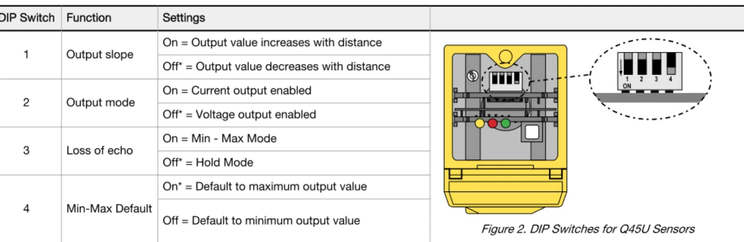
Insert a small, flat-blade screwdriver into the two slots shown in Figure 1. Lift up and remove the black inner cover to expose the 4-position DIP switch. Use these DIP switches to program the output slope, output mode, loss of echo, and min./max. output value default.
DIP Switch Function Settings
1 Output slope On = Output value increases with distance
1 ON 2 3 4
Figure 2. DIP Switches for Q45U Sensors
Off* = Output value decreases with distance
2 Output mode On = Current output enabled Off* = Voltage output enabled
3 Loss of echo On = Min - Max Mode Off* = Hold Mode
4 Min-Max Default
On* = Default to maximum output value
Off = Default to minimum output value
DIP Switch 1: Output Slope
0
Near
Window WindowFar 10 Target Position Analog Output (V dc) Positive Slope Voltage/Current-Sourcing Models 4 20 Analog Output (mA)
Figure 3. Output as a function of target position
On = Direct = Output value (voltage or current) increases with increasing distance of the target from the sensor
Off = Inverse = Output value decreases with increasing distance of the target from the sensor (default setting)
DIP Switch 2: Output Mode
Configure the D/A driver to use either the current output or the voltage output driver. This output function can only be set with the power to the sensor turned off.
On = The 4 to 20 mA current output (white wire) is enabled
Off = The 0 to 10V dc voltage output (black wire) is enabled (default setting) DIP Switch 3: Loss of Echo Mode
Select the output response to the loss of echo. Hold Mode maintains the output at the value present at the time of echo loss. Min-Max Mode drives the output to either the minimum value (0 V or 4 mA) or the maximum value (10 V or 20 mA) when the echo is lost.
On = Min-Max Mode
Off = Hold Mode (default setting) DIP Switch 4: Min-Max Default
Select the output response to loss of echo when Min-Max Mode is selected by DIP switch 3. On = Default to maximum output value at loss of echo (default setting)
Off = Default to minimum output value at loss of echo
Response Speed Adjustments
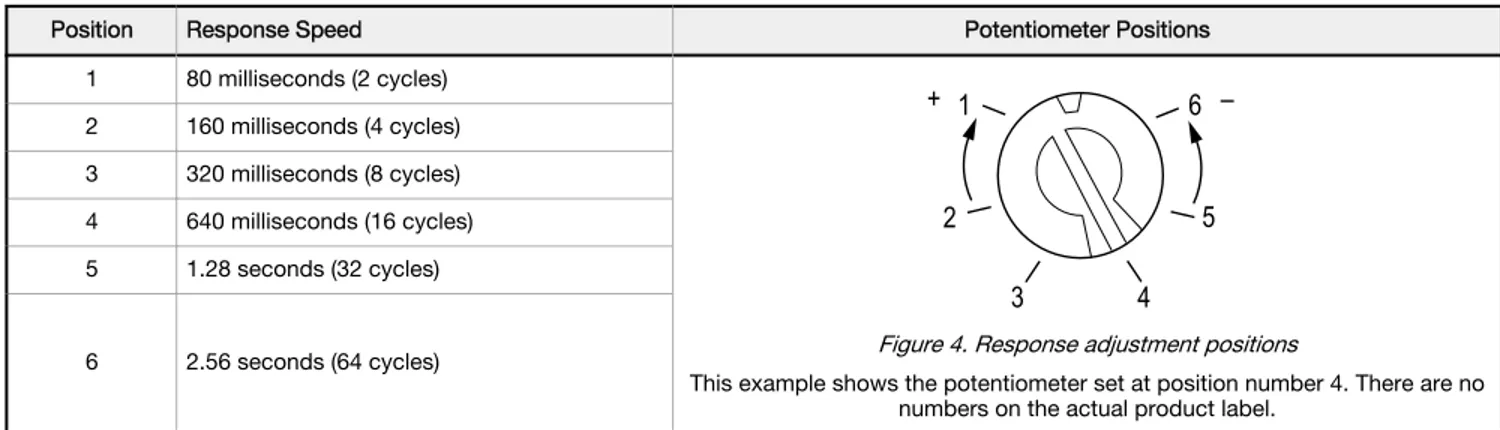
Set the output response speed by aligning the slot of the single-turn potentiometer with one of the marked positions. There are six values for response speed, which relate directly to the number of sensing cycles over which the output value is averaged.
Position Response Speed Potentiometer Positions 1 80 milliseconds (2 cycles)
1
2
3
4
5
6
+
–
Figure 4. Response adjustment positions
This example shows the potentiometer set at position number 4. There are no numbers on the actual product label.
2 160 milliseconds (4 cycles) 3 320 milliseconds (8 cycles) 4 640 milliseconds (16 cycles) 5 1.28 seconds (32 cycles)
6 2.56 seconds (64 cycles)
Programming the Window Limits
Use the Limits button, located under the transparent top cover, to program the near and the far limits.
The near limit may be set as close as 100 mm (4 inches) and the far limit may be set as far as 1400 mm (55 inches) from the transducer face. Minimum window width is 10 mm (0.4 inches). When possible, use the actual target to be sensed when setting the window limits.
The following procedure begins with the sensor in Run mode.
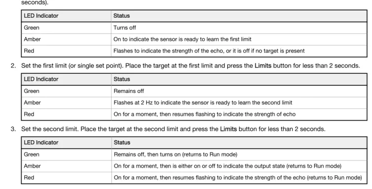
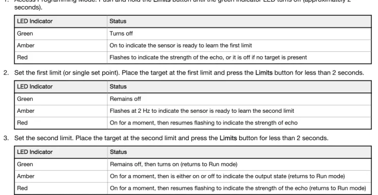
1. Access Programming Mode. Push and hold the Limits button until the green indicator LED turns off (approximately 2 seconds).
LED Indicator Status Green Turns off
Amber On to indicate the sensor is ready to learn the first limit
Red Flashes to indicate the strength of the echo, or it is off if no target is present
2. Set the first limit (or single set point). Place the target at the first limit and press the Limits button for less than 2 seconds.
LED Indicator Status Green Remains off
Amber Flashes at 2 Hz to indicate the sensor is ready to learn the second limit Red On for a moment, then resumes flashing to indicate the strength of echo
3. Set the second limit. Place the target at the second limit and press the Limits button for less than 2 seconds.
LED Indicator Status
Green Remains off, then turns on (returns to Run mode)
Amber On for a moment, then is either on or off to indicate the output state (returns to Run mode) Red On for a moment, then resumes flashing to indicate the strength of the echo (returns to Run mode)
Notes Regarding Window Limit Programming
1. Either the near or far limit may be programmed first.
2. There is a 2-minute time-out for programming the first limit. The sensor returns to Run mode with the previously programmed limits. There is no time-out between programming of the first and second limit.
3. Cancel the programming sequence at any time by pressing and holding the button for longer than 2 seconds. The sensor returns to Run mode with the previously programmed limits.
4. If a limit is rejected during either programming step, the sensor reverts to the first limit programming step, indicated by the Green LED (off), the Red LED (flashing to indicate signal strength), and the Amber LED (on).
5. If both limits are accepted, the sensor returns to Run mode, which is indicated by the Green LED (on).
6. During limit programming, the 5-segment moving dot indicator displays the relative target position between 100 mm (4 inches) and 1500 mm (the maximum recommended far limit position is 1400 mm (55 inches)).
7. If the target is father than 1400 mm (55 inches), the 5th segment of the moving dot indicator flashes to indicate that a valid echo is received, but the target is beyond the recommended 1400 mm (55 inches) maximum far limit.
8. If the target is held at the same position for programming of both limits, the sensor establishes a 10 mm-wide sensing window, centered on the target position.
Remote Programming the Window Limits
Connect the yellow wire of the sensor to a switch or process controller for remote programming of the sensing window limits. The programming procedure is the same as for the button. A remote programming input is generated when +5 to 24 V dc is applied to the yellow wire. The timing diagrams define the required input pulses.H = +5 to 24 V dc
L = Less than 2 V dc (or open circuit)
Notes regarding remote window limit programming:
1. The button is disabled during remote limit programming. (The remote programming input is disabled during push button programming.)
2. Also see the notes regarding window limit programming.
Step 1 Access Limit Programming Mode
Step 2 Set First Limit (Near or Far)
Step 3 Set Second Limit (Far or Near)
T T >2 sec
Wait >0.8 seconds before next input H
L
T 0.04 sec <T< 0.8 sec
Wait >2 seconds before next input H
L
T 0.04 sec <T< 0.8 sec H
L
Specifications
Proximity Mode RangeNear limit: 100 mm (4.0 inches) min Far limit: 1.4 m (55 inches) max Supply Voltage and Current
15 to 24 V dc (10% maximum ripple) at 100 mA, exclusive of load Supply Protection Circuitry
Protected against reverse polarity and transient voltages Performance Specifications
Sensing Repeatability: ±0.1% of the measured distance (±0.25 mm minimum)
Sensing Resolution: 0.25 mm (0.01 in) Analog Output Resolutions: 2 mV, 3 µA
Output Configuration
One voltage sourcing and one current sourcing; one or the other output is enabled by internal programming switch #2. Output function may be programmed by a 4-position DIP switch located on top of the sensor, beneath the transparent o-ring sealed acrylic cover.
Output Rating
Voltage sourcing: 0 to 10 V dc, 10 mA maximum Current sourcing: 4 to 20 mA, 1 to 500 ohm impedance Output Protection Circuitry
Both outputs are protected against continuous overload and short circuit
Indicators
Three status LEDs:
Green solid = power to sensor is ON
Green flashing = current output fault detected (indicates that the 4-20 mA current path to ground has been opened)
Amber solid = target is sensed within the window limits (Amber LED also indicates programming status during setup mode)
Red flashing = indicates relative strength of received echo
5-segment moving dot LED indicates the position of the target within the sensing window
Construction
Molded PBT thermoplastic polyester housing, o-ring sealed transparent acrylic top cover, and stainless steel hardware. Q45U sensors are designed to withstand 1200 psi washdown. The base of cabled models has a 1/2"-14NPS internal conduit thread
Connections
2 m (6.5 ft) or 9 m (30 ft) attached cable, or 5-pin Mini-style or 5-pin Euro-style quick-disconnect fitting
Environmental Rating
Leakproof design is rated IEC IP67; NEMA 6P Operating Temperature
Temperature: –25 to +70 °C (–13 to +158 °F) Maximum relative humidity: 100% Vibration and Mechanical Shock
All models meet Mil. Std. 202F requirements. Method 201A (Vibration: 10 to 60Hz max., double amplitude 0.06-inch, maximum acceleration 10G). Method 213B conditions H & I (Shock: 75G with unit operating; 100G for nonoperation). Also meets IEC 947-5-2 requirements: 30G, 11 ms duration, half sine wave
Application Notes
Minimum target size: 10 mm x 10 mm aluminum plate at 500 mm (20 in) 35 mm × 35 mm aluminum plate at 1.4 m (55 in)
Certifications
Performance Curves
Effective Beam with Plate Target (Typical) Effective Beam with Rod Target (Typical)
Lateral Distance Sensing Distance 2 in 4 in 6 in 2 in 4 in 6 in 50 mm 100 mm 150 mm 50 mm 0 0 100 mm 150 mm 0 200 mm 8 in 400 mm 16 in 600 mm 24 in 800 mm 32 in 1000 mm 40 in 1200 mm 48 in 1400 mm 56 in 100 x 100 mm Plate 10 x 10 mm Plate Lateral Distance Sensing Distance 2 in 4 in 6 in 2 in 4 in 6 in 50 mm 100 mm 150 mm 50 mm 0 0 100 mm 150 mm 0 200 mm 8 in 400 mm 16 in 600 mm 24 in 800 mm 32 in 1000 mm 40 in 1200 mm 48 in 1400 mm 56 in ø 25 mm Rod ø 10 mm Rod
Dimensions
Cabled Models 5-pin Mini-Style QD Models 5-pin Euro-syle QD Models
60.5 mm (2.38 in) 44.5 mm (1.75 in) 69.0 mm (2.72 in) 87.6 mm (3.45 in) 30.0 mm (1.18 in) 7.1 mm (0.28 in) 4.5 mm (#10) Screw Clearance (2) 50.8 mm (2.00 in) 6.4 mm (0.25 in) Transducer Centerline Internal Thread (1/2–14NPSM) External Thread M30 X 1.5 ø 6.1 (0.24 in) 2m (6.5 ft) Cable Hex Nut Supplied Transparent Cover (Gasketed)
View: Sensing Status Output Load Status Power Open to Access:
Push Button for Programming of Sensing Window Limits
14 mm (0.6 in) 15 mm (0.6 in)
Wiring Diagrams for Q45U Sensors with Analog Outputs
Sensor with Attached Cable Sensor with 5-pin Mini-style Quick Disconnect Sensor with 5-pin M12/Euro-style QuickDisconnect
1 2 3 – 4 5 15–24 V dc 4–20 mA 0–10 V Remote teach (+5–24 V dc) Load Load + shield 1 2 3 – 4 5 4–20 mA 0–10 V Remote teach (+5–24 V dc) Load Load + 15–24 V dc shield 1 2 3 – 4 5 4–20 mA 0–10 V Remote teach (+5–24 V dc) Load Load + 15–24 V dc shield
Banner Engineering Corp recommends the shield wire be connected to earth ground or dc common. 1 = brown 2 = white 3 = blue 4 = black 5 = gray or yellow 1 = brown 2 = white 3 = blue 4 = black 5 = yellow 1 = brown 2 = white 3 = blue 4 = black 5 = gray
Accessories
Cordsets
5-Pin Mini-Style Cordsets—with Shield
Model Length Style Dimensions Pinout (Female)
MBCC2-506 1.83 m (6 ft) Straight 7/8-16UN-2B ø 25.5 52 Typ. 4 3 1 5 2 1 = Brown 2 = White 3 = Blue 4 = Black 5 = Yellow MBCC2-512 3.66 m (12 ft) MBCC2-530 9.14 m (30 ft)
5-Pin Threaded M12/Euro-Style Cordsets—with Shield
Model Length Style Dimensions Pinout (Female)
MQDEC2-506 1.83 m (6 ft) Straight 44 Typ. ø 14.5 M12 x 1 2 3 4 1 5 1 = Brown 2 = White 3 = Blue 4 = Black 5 = Gray MQDEC2-515 4.57 m (15 ft) MQDEC2-530 9.14 m (30 ft) MQDEC2-550 15.2 m (50 ft) MQDEC2-506RA 1.83 m (6 ft) Right-Angle 32 Typ. [1.26"] 30 Typ. [1.18"] ø 14.5 [0.57"] M12 x 1 MQDEC2-515RA 4.57 m (15 ft) MQDEC2-530RA 9.14 m (30 ft) MQDEC2-550RA 15.2 m (50 ft) Brackets SMB30S
• Swivel bracket with 30 mm mounting hole for sensor • Adjustable captive swivel ball • Black reinforced thermoplastic
polyester
• Stainless steel mounting and swivel locking hardware included 63.5 mm [2.5”] 50.8 mm [2”] M5 x 0.8 x 30 mmScrew (2) Not Shown: (2) M5 x 0.8 x 60 mm screws are supplied for clamping bracket together
43.2 mm [1.7”] 25.4 mm [1”] 82.5 mm [3.25”] 12.2 mm [0.48”] SMB30C
• 30 mm split clamp, black PBT bracket
• Stainless steel mounting hardware included • Mounting hole for 30 mm
sensor 66 56 13 A B
Hole center spacing: A=ø 45 Hole size: B=ø 27.2
SMB30MM
• 12-ga. stainless steel bracket with curved mounting slots for versatile orientation • Clearance for M6 (¼ in)
hardware
• Mounting hole for 30 mm sensor 70 57 A B C 57
Hole center spacing: A = 51, A to B = 25.4 Hole size: A = 42.6 x 7, B = ø 6.4, C = ø 30.1
Banner Engineering Corp. Limited Warranty
Banner Engineering Corp. warrants its products to be free from defects in material and workmanship for one year following the date of shipment. Banner Engineering Corp. will repair or replace, free of charge, any product of its manufacture which, at the time it is returned to the factory, is found to have been defective during the warranty period. This warranty does not cover damage or liability for misuse, abuse, or the improper application or installation of the Banner product.
THIS LIMITED WARRANTY IS EXCLUSIVE AND IN LIEU OF ALL OTHER WARRANTIES WHETHER EXPRESS OR IMPLIED (INCLUDING, WITHOUT LIMITATION, ANY WARRANTY OF MERCHANTABILITY OR FITNESS FOR A PARTICULAR PURPOSE), AND WHETHER ARISING UNDER COURSE OF PERFORMANCE, COURSE OF DEALING OR TRADE USAGE. This Warranty is exclusive and limited to repair or, at the discretion of Banner Engineering Corp., replacement. IN NO EVENT SHALL BANNER ENGINEERING CORP. BE LIABLE TO BUYER OR ANY OTHER PERSON OR ENTITY FOR ANY EXTRA COSTS, EXPENSES, LOSSES, LOSS OF PROFITS, OR ANY INCIDENTAL, CONSEQUENTIAL OR SPECIAL DAMAGES RESULTING FROM ANY PRODUCT DEFECT OR FROM THE USE OR INABILITY TO USE THE PRODUCT, WHETHER ARISING IN CONTRACT OR WARRANTY, STATUTE, TORT, STRICT LIABILITY, NEGLIGENCE, OR OTHERWISE.
Banner Engineering Corp. reserves the right to change, modify or improve the design of the product without assuming any obligations or liabilities relating to any product previously manufactured by Banner Engineering Corp. Any misuse, abuse, or improper application or installation of this product or use of the product for personal protection applications when the product is identified as not intended for such purposes will void the product warranty. Any modifications to this product without prior express approval by Banner Engineering Corp will void the product warranties. All specifications published in this document are subject to change; Banner reserves the right to modify product specifications or update documentation at any time. Specifications and product information in English supersede that which is provided in any other language. For the most recent version of any documentation, refer to:
Datasheet
Piezoelectric proximity mode sensor with push button programming of sensing window limits; bipolar discrete outputs
• Ultrasonic proximity detection from 100 mm to 1400 mm (4 in to 55 in) • Push-button TEACH-mode programming of sensing window limits • Digital filtering for exceptional immunity to electrical and acoustic noise • 12 to 24 V dc operation
• Bipolar outputs: one NPN (sinking) and one PNP (sourcing)
• ON/OFF presence detection or HIGH/LOW level control are switch selectable
• Wide operating temperature range of –25 °C to +70 °C (–13 °F to +158 °F); some models are available with temperature compensation
• Rugged design for use in demanding sensing environments; rated IEC IP67, NEMA 6P • Choose models with an integral unterminated 2 m (6.5 ft) or 9 m (30 ft) cable, or with a
Mini-style or M12/Euro-Mini-style quick-disconnect connection • External enable/disable feature for remote gating control Analog models and models with other ranges are also available
WARNING: Not To Be Used for Personnel Protection
Never use this device as a sensing device for personnel protection. Doing so could lead to serious injury or death. This device does not include the self-checking redundant circuitry necessary to allow its use in personnel safety applications. A sensor failure or malfunction can cause either an energized or de-energized sensor output condition.
Models
Model Temperature
Compensation Connection Response Time
Q45UBB63DA
No
2 m (6.5 ft)
Programmable for 20, 40, 160, or 640 milliseconds
Q45UBB63DAQ Integral 5-pin Mini quick disconnect
Q45UBB63DAQ6 Integral 5-pin M12/Euro-style male quick disconnect (QD)
Q45UBB63DAC
Yes
2 m (6.5 ft)
Q45UBB63DACQ Integral 5-pin Mini quick disconnect
Q45UBB63DACQ6 Integral 5-pin M12/Euro-style male quick disconnect (QD)
Models with Temperature Compensation—An increase in air temperature shifts both sensing window limits closer to the sensor. Conversely, a decrease in air temperature shifts both limits further away from the sensor. The shift is approximately 3.5% of the limit distance for a 20°C change in temperature. Temperature compensated models maintain the position of both sensing window limits to within 1% of each limit distance over the range of from 0° to +50°C, and to within 2.5% over the full operating range of from -25° to +70°C.
To order the 9 m (30 ft) cable models, add the suffix “W/30” to the model number of any cabled sensor (e.g., Q45UBB63DA W/30). Models with a QD connector require an optional mating cable.
Overview
Near and Far Sensing Limit Settings. The Q45U features a single push button for programming the sensing window near and far limits.
Status Indicators. Status indicator LEDs are visible through the transparent, o-ring sealed polycarbonate top cover. Indicator function in the Run mode is as follows:
• The green LED is on when power is applied to the sensor and flashes to indicate an overloaded output. • The red LED flashes when an echo is received; the flash rate is proportional to echo strength.
U-GAGE
Q45UBB Ultrasonic Sensor
• The amber LED is on when the outputs are conducting. Limits N 1 2 3 4 5
3
4
5
1
2
6
Figure 1. Q45U Long-Range Features
1. Button for programming the sensing window limits 2. 5-Segment target position indicator (N = Near) 3. Green power indicator
4. Red signal indicator 5. Amber output indicator
6. Slots for removing the inner cover
The 5-segment moving dot LED indicator displays the relative position of the target within the programmed sensing window. The #1 LED flashes when the target is closer than the near limit. The #5 LED flashes when the target is beyond the far limit.
Setting the DIP Switches
Follow these steps to select the output response settings.
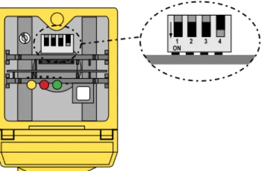
Important: Disconnect the power before making any internal adjustments. 1. Insert a small flat-blade screwdriver into the slots.
2. Lift up and remove the black inner cover to expose the 4-position DIP switch.
3. Use the DIP switches to program the following functions: 1 ON 2 3 4
Figure 2. Q45U Programming Switches
* Factory default setting
Description 1 2 3 4
ON/OFF Mode: Normally closed output (output energizes when target is absent)
HIGH/LOW Mode: Pump out ON
ON/OFF Mode: Normally open (output energizes when target sensed)
HIGH/LOW Mode: Pump in OFF *
Select HIGH/LOW Mode (fill level control) ON
Select ON/OFF Mode (the output follows the sensing action) OFF *
Response time (20 ms/cycle): 1 cycle (20 ms) OFF OFF
Response time (20 ms/cycle): 2 cycles (40 ms) ON OFF
Response time (20 ms/cycle): 8 cycles (160 ms) OFF * ON *
Response time (20 ms/cycle): 32 cycles (640 ms) ON ON
Important: A response setting of 2 cycles or higher is recommended for optimum sonic and electrical noise immunity. Always use the slowest acceptable response speed for your application. Single cycle update is only recommended for short range (< 50 cm) applications looking for a stationary target.
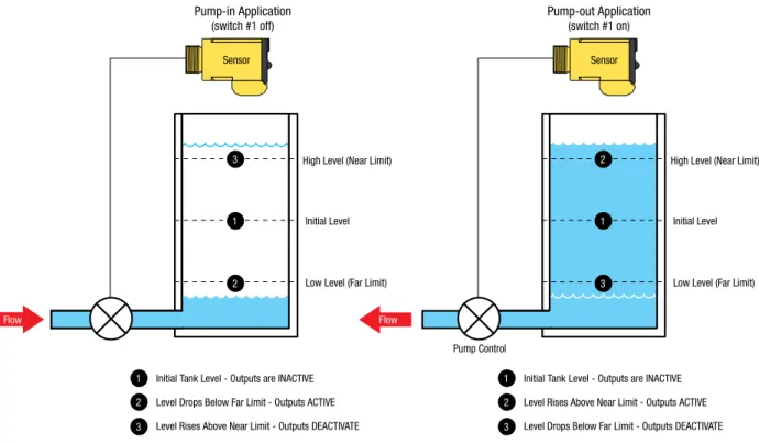
Sensor
High Level (Near Limit)
Pump-in Application
(switch #1 off)
Pump-out Application
(switch #1 on)
Low Level (Far Limit) Initial Level
1 Initial Tank Level - Outputs are INACTIVE
2 3
Level Drops Below Far Limit - Outputs ACTIVE Level Rises Above Near Limit - Outputs DEACTIVATE
2 1 3
Flow Flow
1 Initial Tank Level - Outputs are INACTIVE
2 3
Level Rises Above Near Limit - Outputs ACTIVE Level Drops Below Far Limit - Outputs DEACTIVATE
Sensor
Pump Control
High Level (Near Limit)
Low Level (Far Limit) Initial Level
3 1 2
Note: If no echo is received by the sensor, the target is assumed to be beyond the far window limit.
Figure 3. High/Low Control (DIP Switch 2 in ON)
The HIGH/LOW mode (DIP switch 2 is ON) provides the switching logic required for fill-level, web tensioning control, and similar applications. In the HIGH/LOW mode, the output energizes when the target reaches the first sensing window limit, and stays energized until the target moves to the second limit. The output then de-energizes at the second limit and does not re-energize until the target moves, again, to the first limit. The figure shows how pumping action might be controlled, directly, by the sensor in a fill-level application.
Programming the Window Limit
Use the Limits button, located under the transparent top cover, to program the near and the far limits.
The near limit may be set as close as 100 mm (4 in) and the far limit may be set as far as 1400 mm (55 in) from the transducer face. The minimum window width is 10 mm (0.4 in). When possible, use the actual target to be sensed when setting the window limits. Programming the window limit begins with the sensor in Run mode.
1. Push and hold the Limits button until the green LED turns off (approximately 2 seconds).
Green LED Amber LED Red LED
Off On to indicate the sensor is ready toprogram the first limit Flashes to indicate the strength of theecho; Off if no target is present
2. Set the first limit (near or far) by placing the target at the first limit and pressing the Limits button for less than 2 seconds.
Green LED Amber LED Red LED
Off Flashes at 2 Hz to indicate the sensor isready to program the second limit On for a moment, then resumes flashing toindicate the strength of the echo
3. Set the second limit (far or near) by placing the target at the second limit and pressing the Limits button for less than 2 seconds.
Green LED Amber LED Red LED Off, then turns on when the sensor returns
to Run mode
On for a moment, then is either on or off to indicate the output state when the sensor returns to Run mode
On for a moment, then resumes flashing to indicate the strength of the echo when the sensor returns to Run mode
1. Either the near or far limit may be programmed first.
2. There is a 2-minute timeout for programming of the first limit. The sensor returns to Run mode with the previously programmed limits. There is no timeout between the programming of the first and second limit.
3. Cancel the programming sequence at any time by pressing and holding the Limits button for ≥ 2 seconds. The sensor returns to Run mode with the previously programmed limits.
4. During limit programming, the 5-segment moving dot indicator displays the relative target position between 0 m and 1500 mm. The maximum recommended far limit position is 1400 mm.
5. If the target is positioned between 1400 mm and 1500 mm, the 5th segment of the moving dot indicator flashes to indicate that a valid echo is received, but the target is beyond the recommended 1400 mm maximum far limit.
6. If a limit is rejected during either programming step, the sensor reverts to the first limit programming step. This is indicated by the green LED (OFF), red LED (flashing to indicate signal strength), and the amber LED (ON).
7. If both limits are accepted, the sensor returns to Run mode, which is indicated by the green LED (ON).
8. If the target is held at the same position for programming of both limits, the sensor establishes a 10 mm wide sensing window, centered on the target position.
Specifications
Supply Voltage and Current12 to 24 V dc (10% maximum ripple) at 100 mA, exclusive of load Proximity Mode Range
Near limit: 100 mm (4 in) minimum Far limit: 1.4 m (55 in)
Supply Protection Circuitry
Protected against reverse polarity and transient voltages Output Rating
150 mA maximum (each)
Off-state leakage current: < 25 microamp at 24 V dc
On-state saturation voltage: < 1.5 V at 10 mA; < 2.0 V at 150 mA
Output Configuration
Bipolar: one current sourcing (PNP) and one current sinking (NPN) open-collector transistor
Use the 4-position DIP switch to select the following:
Switch 1: Output normally open/normally closed (pump in/pump out) Switch 2: High/Low level control mode or on/off presence sensing mode
Switch 3 & 4: Response speed selection (digital filter) Environmental Rating
Leakproof design is rated IEC IP67; NEMA 6P
Performance Specifications
Repeatability: ±0.1% of measured distance (±0.25 mm min) Minimum Window Width: 10 mm (0.4 in)
Hysteresis: 5 mm (0.2 in) Output Protection Circuitry
Protected against false pulse on power-up and continuous overload or short-circuit of outputs
Construction
Molded PBT thermoplastic polyester housing, o-ring sealed transparent acrylic top cover, and stainless steel hardware.
Q45U sensors are designed to withstand 1200 psi washdown. The base of cabled models has a 1/2"-14 NPS internal conduit thread Connections
2 m (6.5 ft) or 9 m (30 ft) attached cable, or 5-pin Mini-style or 5-pin M12/ Euro-style quick disconnect fitting
Hysteresis
ON/OFF mode: 5 mm HIGH/LOW mode: 0 mm Certifications
Indicators
Three status LEDs:
Green ON = power to sensor is ON Green flashing = output is overloaded
Amber ON = outputs are conducting (in Run mode); or programming status (in Setup mode)
Red flashing = indicates relative strength of received echo 5-segment moving dot LED indicates the position of the target within the sensing window
Operating Conditions
Temperature: –25 °C to +70 °C (–13 °F to +158 °F) Maximum relative humidity: 100%
Vibration and Mechanical Shock
All models meet Mil Std. 202F requirements. Method 201A (vibration: 10 Hz to 60 Hz max., double amplitude 0.06 inch, maximum acceleration 10G). Also meets IEC 947-5-2 requirements: 30G 11 ms duration, half sine wave. Method 213B conditions H & I (Shock: 75G with unit operating; 100G for non-operation).
Application Notes
Minimum target size: 10 mm × 10 mm aluminum plate at 500 mm (20 in) and 35 mm × 35 mm aluminum plate at 1.4 m (55 in)
Enable/Disable: Connect the yellow wire to +5 to 24 V dc to enable the sensor and 0 to +2 V dc to disable the sensor. When the sensor is disabled, the last output state is held until the sensor is re-enabled. Hold the wire to the appropriate voltage for at least 40 ms to enable or disable the sensor.
Performance Curves
Effective Beam with Plate Target (Typical) Effective Beam with Rod Target (Typical)
Lateral Distance Sensing Distance 2 in 4 in 6 in 2 in 4 in 6 in 50 mm 100 mm 150 mm 50 mm 0 0 100 mm 150 mm 0 200 mm 8 in 400 mm 16 in 600 mm 24 in 800 mm 32 in 1000 mm 40 in 1200 mm 48 in 1400 mm 56 in 100 x 100 mm Plate 10 x 10 mm Plate Lateral Distance Sensing Distance 2 in 4 in 6 in 2 in 4 in 6 in 50 mm 100 mm 150 mm 50 mm 0 0 100 mm 150 mm 0 200 mm 8 in 400 mm 16 in 600 mm 24 in 800 mm 32 in 1000 mm 40 in 1200 mm 48 in 1400 mm 56 in ø 25 mm Rod ø 10 mm Rod
Dimensions
Cabled Models 5-pin Mini-Style QD Models 5-pin Euro-syle QD Models
60.5 mm (2.38 in) 44.5 mm (1.75 in) 69.0 mm (2.72 in) 87.6 mm (3.45 in) 30.0 mm (1.18 in) 7.1 mm (0.28 in) 4.5 mm (#10) Screw Clearance (2) 50.8 mm (2.00 in) 6.4 mm (0.25 in) Transducer Centerline Internal Thread (1/2–14NPSM) External Thread M30 X 1.5 ø 6.1 (0.24 in) 2m (6.5 ft) Cable Hex Nut Supplied Transparent Cover (Gasketed)
View: Sensing Status Output Load Status Power Open to Access:
Push Button for Programming of Sensing Window Limits
14 mm (0.6 in) 15 mm (0.6 in)
Wiring Diagrams
Q45U Sensor with Attached Cable Q45U Sensor with 5-pin Mini-style or Euro-style QD Key
1 2 3 + − 4 5 Load 12–24 V dc Enable (+5–24 V dc) Load shield 1 2 3 + − 4 5 Load Load 12–24 V dc Enable (+5–24 V dc) shield 1 = Brown 2 = White 3 = Blue 4 = Black
5 = Gray (Euro-style) or yellow (Mini-style)
Banner Engineering Corp. recommends that the shield wire be connected to earth ground or dc common.
Accessories
Cordsets
5-Pin Mini-Style Cordsets—with Shield
Model Length Style Dimensions Pinout (Female)
MBCC2-506 1.83 m (6 ft) Straight 7/8-16UN-2B ø 25.5 52 Typ. 4 3 1 5 2 1 = Brown 2 = White 3 = Blue 4 = Black 5 = Yellow MBCC2-512 3.66 m (12 ft) MBCC2-530 9.14 m (30 ft)
5-Pin Threaded M12/Euro-Style Cordsets—with Shield
Model Length Style Dimensions Pinout (Female)
MQDEC2-506 1.83 m (6 ft) Straight 44 Typ. ø 14.5 M12 x 1 2 3 4 1 5 1 = Brown 2 = White 3 = Blue 4 = Black 5 = Gray MQDEC2-515 4.57 m (15 ft) MQDEC2-530 9.14 m (30 ft) MQDEC2-550 15.2 m (50 ft) MQDEC2-506RA 1.83 m (6 ft) Right-Angle 32 Typ. [1.26"] 30 Typ. [1.18"] ø 14.5 [0.57"] M12 x 1 MQDEC2-515RA 4.57 m (15 ft) MQDEC2-530RA 9.14 m (30 ft) MQDEC2-550RA 15.2 m (50 ft) Brackets SMB30S
• Swivel bracket with 30 mm mounting hole for sensor • Adjustable captive swivel ball • Black reinforced thermoplastic
polyester
• Stainless steel mounting and swivel locking hardware included 63.5 mm [2.5”] 50.8 mm [2”] M5 x 0.8 x 30 mmScrew (2) Not Shown: (2) M5 x 0.8 x 60 mm screws are supplied for clamping bracket together
43.2 mm [1.7”] 25.4 mm [1”] 82.5 mm [3.25”] 12.2 mm [0.48”] SMB30C
• 30 mm split clamp, black PBT bracket
• Stainless steel mounting hardware included • Mounting hole for 30 mm
sensor 66 56 13 A B
Hole center spacing: A=ø 45 Hole size: B=ø 27.2
SMB30MM
• 12-ga. stainless steel bracket with curved mounting slots for versatile orientation • Clearance for M6 (¼ in)
hardware
• Mounting hole for 30 mm sensor 70 57 A B C 57
Hole center spacing: A = 51, A to B = 25.4 Hole size: A = 42.6 x 7, B = ø 6.4, C = ø 30.1
Banner Engineering Corp. Limited Warranty
Banner Engineering Corp. warrants its products to be free from defects in material and workmanship for one year following the date of shipment. Banner Engineering Corp. will repair or replace, free of charge, any product of its manufacture which, at the time it is returned to the factory, is found to have been defective during the warranty period. This warranty does not cover damage or liability for misuse, abuse, or the improper application or installation of the Banner product.
THIS LIMITED WARRANTY IS EXCLUSIVE AND IN LIEU OF ALL OTHER WARRANTIES WHETHER EXPRESS OR IMPLIED (INCLUDING, WITHOUT LIMITATION, ANY WARRANTY OF MERCHANTABILITY OR FITNESS FOR A PARTICULAR PURPOSE), AND WHETHER ARISING UNDER COURSE OF PERFORMANCE, COURSE OF DEALING OR TRADE USAGE. This Warranty is exclusive and limited to repair or, at the discretion of Banner Engineering Corp., replacement. IN NO EVENT SHALL BANNER ENGINEERING CORP. BE LIABLE TO BUYER OR ANY OTHER PERSON OR ENTITY FOR ANY EXTRA COSTS, EXPENSES, LOSSES, LOSS OF PROFITS, OR ANY INCIDENTAL, CONSEQUENTIAL OR SPECIAL DAMAGES RESULTING FROM ANY PRODUCT DEFECT OR FROM THE USE OR INABILITY TO USE THE PRODUCT, WHETHER ARISING IN CONTRACT OR WARRANTY, STATUTE, TORT, STRICT LIABILITY, NEGLIGENCE, OR OTHERWISE.
Banner Engineering Corp. reserves the right to change, modify or improve the design of the product without assuming any obligations or liabilities relating to any product previously manufactured by Banner Engineering Corp. Any misuse, abuse, or improper application or installation of this product or use of the product for personal protection applications when the product is identified as not intended for such purposes will void the product warranty. Any modifications to this product without prior express approval by Banner Engineering Corp will void the product warranties. All specifications published in this document are subject to change; Banner reserves the right to modify product specifications or update documentation at any time. Specifications and product information in English supersede that which is provided in any other language. For the most recent version of any documentation, refer to:
Datasheet
Piezoelectric proximity mode sensors with push-button programming of sensing window limits
• Ultrasonic proximity detection from 250 mm to 3.0 m (9.8 in to 118 in) • Push-button TEACH-mode programming of sensing window limits • Digital filtering for exceptional immunity to electrical and acoustic noise • 15 to 24 V dc operation
• Selectable 0 to 10 V dc voltage sourcing or 4 to 20 mA current sourcing analog outputs
• Selectable output slope: positive or negative with increasing target distance • Wide operating temperature range of –25 °C to +70 °C (–13 °F to +158 °F); all
models include temperature compensation
• Rugged design for use in demanding sensing environments; rated IEC IP67, NEMA 6P
• Choose models with an integral unterminated 2 m (6.5 ft) or 9 m (30 ft) cable, or with a Mini-style or M12/Euro-style quick-disconnect connection
• Input for remote TEACH-mode programming of window limits
Models Cable 1 Output Type Response Time Q45ULIU64BCR 2 m (6.5 ft)
Selectable 0 to 10 V dc or 4 to 20 mA sourcing
Adjustable from 80 milliseconds to 2.56 seconds
Q45ULIU64BCRQ 5-pin Mini-style QD Q45ULIU64BCRQ6 5-pin M12/Euro-style QD
WARNING: Not To Be Used for Personnel Protection
Never use this device as a sensing device for personnel protection. Doing so could lead to serious injury or death. This device does not include the self-checking redundant circuitry necessary to allow its use in personnel safety applications. A sensor failure or malfunction can cause either an energized or de-energized sensor output condition.
Temperature Compensation
All models listed above feature temperature compensation. An increase in air temperature shifts both sensing window limits closer to the sensor. Conversely, a decrease in air temperature shifts both limits further away from the sensor. The shift is approximately 3.5% of the limit distance for a 20 °C change in temperature.
Temperature compensated models maintain the position of both sensing window limits to within 1% of each limit distance over the 0 °C to +50 °C (+32 °F to +122 °F) range, and to within 2.5% over the full operating range of –25 °C to +70 °C (–13 °F to +158 °F).
1 To order the 9 m (30 ft) cable models, add the suffix "W/30" to the cabled model number. For example, Q45ULIU64BCR W/30. Models with a quick disconnect (QD) connector require a mating cable.
Q45U Ultrasonic Sensors with Analog Outputs
(Long Range)
Overview
Limits N 1 2 3 4 5 3 4 5 1 2 7 Resp. Speed + – 6Figure 1. Q45U with Analog Outputs Features
1 - Push button for programming sensing window limits 2 - 5-segment target position indicator (N = near) 3 - Green POWER indicator LED
4 - Red SIGNAL indicator LED 5 - Amber OUTPUT indicator LED 6 - Response adjustment 7 - Slots for removing inner cover
Status Indicators
Status indicator LEDs are visible through the transparent, o-ring sealed acrylic top cover. Indicator function in the Run mode is, as follows:
• The green LED is on when power is applied to the sensor and flashes to indicate a current output fault. • The red LED is on when an echo is received and flashes at a rate proportional to echo strength. • The amber LED is on when the target is within the operating window limits.
The 5-segment moving dot LED indicator displays the relative position of the target within the programmed sensing window. LED 1 flashes when the target is closer than the near limit. LED 5 flashes when the target is beyond the far limit.
Configuring a Sensor
Output Response Settings
Important: Remove power before making any internal adjustments.
Insert a small, flat-blade screwdriver into the two slots shown in Figure 1. Lift up and remove the black inner cover to expose the 4-position DIP switch. Use these DIP switches to program the output slope, output mode, loss of echo, and min./max. output value default.
DIP Switch Function Settings
1 Output slope On = Output value increases with distance
1 ON 2 3 4
Figure 2. DIP Switches for Q45U Sensors
Off* = Output value decreases with distance
2 Output mode On = Current output enabled Off* = Voltage output enabled
3 Loss of echo On = Min - Max Mode Off* = Hold Mode
4 Min-Max Default
On* = Default to maximum output value
Off = Default to minimum output value
DIP Switch 1: Output Slope
0
Near
Window WindowFar 10 Target Position Analog Output (V dc) Positive Slope Voltage/Current-Sourcing Models 4 20 Analog Output (mA)
Figure 3. Output as a function of target position
On = Direct = Output value (voltage or current) increases with increasing distance of the target from the sensor
Off = Inverse = Output value decreases with increasing distance of the target from the sensor (default setting)
DIP Switch 2: Output Mode
Configure the D/A driver to use either the current output or the voltage output driver. This output function can only be set with the power to the sensor turned off.
On = The 4 to 20 mA current output (white wire) is enabled
Off = The 0 to 10V dc voltage output (black wire) is enabled (default setting) DIP Switch 3: Loss of Echo Mode
Select the output response to the loss of echo. Hold Mode maintains the output at the value present at the time of echo loss. Min-Max Mode drives the output to either the minimum value (0 V or 4 mA) or the maximum value (10 V or 20 mA) when the echo is lost.
On = Min-Max Mode
Off = Hold Mode (default setting) DIP Switch 4: Min-Max Default
Select the output response to loss of echo when Min-Max Mode is selected by DIP switch 3. On = Default to maximum output value at loss of echo (default setting)
Off = Default to minimum output value at loss of echo
Response Speed Adjustments
Set the output response speed by aligning the slot of the single-turn potentiometer with one of the marked positions. There are six values for response speed, which relate directly to the number of sensing cycles over which the output value is averaged.
Position Response Speed Potentiometer Positions 1 80 milliseconds (2 cycles)
1
2
3
4
5
6
+
–
Figure 4. Response adjustment positions
This example shows the potentiometer set at position number 4. There are no numbers on the actual product label.
2 160 milliseconds (4 cycles) 3 320 milliseconds (8 cycles) 4 640 milliseconds (16 cycles) 5 1.28 seconds (32 cycles)
6 2.56 seconds (64 cycles)
Programming the Window Limits
Use the Limits button, located under the transparent top cover, to program the near and the far limits.
The near limit may be set as close as 250 mm (9.8 inches) and the far limit may be set as far as 3.0 m (118 inches) from the transducer face. Minimum window width is 25 mm (1 inch). When possible, use the actual target to be sensed when setting the window limits.
The following procedure begins with the sensor in Run mode.
1. Access Programming Mode. Push and hold the Limits button until the green indicator LED turns off (approximately 2 seconds).
LED Indicator Status Green Turns off
Amber On to indicate the sensor is ready to learn the first limit
Red Flashes to indicate the strength of the echo, or it is off if no target is present
2. Set the first limit (or single set point). Place the target at the first limit and press the Limits button for less than 2 seconds.
LED Indicator Status Green Remains off
Amber Flashes at 2 Hz to indicate the sensor is ready to learn the second limit Red On for a moment, then resumes flashing to indicate the strength of echo
3. Set the second limit. Place the target at the second limit and press the Limits button for less than 2 seconds.
LED Indicator Status
Green Remains off, then turns on (returns to Run mode)
Amber On for a moment, then is either on or off to indicate the output state (returns to Run mode) Red On for a moment, then resumes flashing to indicate the strength of the echo (returns to Run mode)
Notes Regarding Window Limit Programming
1. Either the near or far limit may be programmed first.
2. There is a 2-minute time-out for programming the first limit. The sensor returns to Run mode with the previously programmed limits. There is no time-out between programming of the first and second limit.
3. Cancel the programming sequence at any time by pressing and holding the button for longer than 2 seconds. The sensor returns to Run mode with the previously programmed limits.
4. If a limit is rejected during either programming step, the sensor reverts to the first limit programming step, indicated by the Green LED (off), the Red LED (flashing to indicate signal strength), and the Amber LED (on).
5. If both limits are accepted, the sensor returns to Run mode, which is indicated by the Green LED (on).
6. During limit programming, the 5-segment moving dot indicator displays the relative target position between 250 mm (9.8 inches) and 4.0 m (the maximum recommended far limit position is 3.0 m (118 inches)).
7. If the target is father than 3.0 m (118 inches), the 5th segment of the moving dot indicator flashes to indicate that a valid echo is received, but the target is beyond the recommended 3.0 m (118 inches) maximum far limit.
8. If the target is held at the same position for programming of both limits, the sensor establishes a 50 mm-wide sensing window, centered on the target position.
Remote Programming the Window Limits
Connect the yellow wire of the sensor to a switch or process controller for remote programming of the sensing window limits. The programming procedure is the same as for the button. A remote programming input is generated when +5 to 24 V dc is applied to the yellow wire. The timing diagrams define the required input pulses.H = +5 to 24 V dc
L = Less than 2 V dc (or open circuit)
Notes regarding remote window limit programming:
1. The button is disabled during remote limit programming. (The remote programming input is disabled during push button programming.)
2. Also see the notes regarding window limit programming.
Step 1 Access Limit Programming Mode
Step 2 Set First Limit (Near or Far)
Step 3 Set Second Limit (Far or Near)
T T >2 sec
Wait >0.8 seconds before next input H
L
T 0.04 sec <T< 0.8 sec
Wait >2 seconds before next input H
L
T 0.04 sec <T< 0.8 sec H
L
Specifications
Proximity Mode RangeNear limit: 250 mm (9.8 inches) min Far limit: 3.0 m (118 inches) max
The far limit may be extended as far as 3.9 m for good acoustical targets (hard surfaces with area > 100 cm²)
Supply Voltage and Current
15 to 24V dc (10% maximum ripple) at 100 mA, exclusive of load Supply Protection Circuitry
Protected against reverse polarity and transient voltages
Output Configuration
One voltage sourcing and one current sourcing; one or the other output is enabled by internal programming switch #2. Output function may be programmed by a 4-position DIP switch located on top of the sensor, beneath the transparent o-ring sealed acrylic cover.
Output Rating
Voltage sourcing: 0 to 10V dc, 10 mA maximum Current sourcing: 4 to 20 mA, 1 to 500 ohm impedance Output Protection Circuitry
Both outputs are protected against continuous overload and short circuit Indicators
Three status LEDs:
Green solid = power to sensor is ON
Green flashing = current output fault detected (indicates that the 4-20 mA current path to ground has been opened)
Amber solid = target is sensed within the window limits (Amber LED also indicates programming status during setup mode)
Red flashing = indicates relative strength of received echo
5-segment moving dot LED indicates the position of the target within the sensing window
Construction
Molded PBT thermoplastic polyester housing, o-ring sealed transparent acrylic top cover, and stainless steel hardware. Q45U sensors are designed to withstand 1200 psi washdown. The base of cabled models has a 1/2"-14NPS internal conduit thread
Connections
2 m (6.5 ft) or 9 m (30 ft) attached cable, or 5-pin Mini-style or 5-pin Euro-style quick-disconnect fitting
Certifications
Performance Specifications
Sensing Repeatability: ±0.1% of the measured distance (±0.50 mm minimum)
Sensing Resolution: 0.50 mm (0.02 in) Analog Output Resolutions: 2 mV, 3 μA Environmental Rating
Leakproof design is rated IEC IP67; NEMA 6P Operating Temperature
Temperature: –25 to +70 °C (–13 to +158 °F) Maximum relative humidity: 100% Vibration and Mechanical Shock
All models meet Mil. Std. 202F requirements. Method 201A (Vibration: 10 to 60Hz max., double amplitude 0.06-inch, maximum acceleration 10G). Method 213B conditions H & I (Shock: 75G with unit operating; 100G for nonoperation). Also meets IEC 947-5-2 requirements: 30G, 11 ms duration, half sine wave
Application Notes
Minimum target size: 50 mm x 50 mm aluminum plate at 3.0 m (118")
Performance Curves
Effective Beam with 100 × 100 mm Plate Target (Typical) Effective Beam with 2.5 cm Rod Target (Typical)
Lateral Distance Sensing Distance 4 in 8 in 12 in 16 in 4 in 8 in 12 in 16 in 100 mm 200 mm 300 mm 100 mm 0 0 200 mm 300 mm 400 mm 400 mm 0 500 mm 20 in 1000 mm40 in 1500 mm60 in 2000 mm80 in 2500 mm100 in 3000 mm120 in 3500 mm140 in 4000 mm160 in Lateral Distance Sensing Distance 4 in 8 in 12 in 16 in 4 in 8 in 12 in 16 in 100 mm 200 mm 300 mm 100 mm 0 0 200 mm 300 mm 400 mm 400 mm 0 500 mm 20 in 1000 mm40 in 1500 mm60 in 2000 mm80 in 2500 mm100 in 3000 mm120 in 3500 mm140 in 4000 mm160 in
Dimensions
Cabled Models 5-pin Mini-style QD Models 5-pin Euro-style QD Models
79.4 mm (3.13") 44.5 mm (1.75") 69.0 mm (2.72") 87.6 mm (3.45") 30.0 mm (1.18") Internal Thread: (1/2 NPSM) External Thread: (M30 x 1.5) ø6.1 mm (.24") 2 m (6.5') Cable 7.1 mm (0.28") 4.5 mm (#10) Screw Clearance (2) 50.3 mm (1.98") 6.4 mm (0.25") Transducer Centerline Transparent Cover (Gasketed)
View: Sensing Status Output Load Status Power Open to Access:
Push Button for Programming of Sensing Window Limits
Hex Nut Supplied
14 mm (0.6") 15 mm (0.6")
Wiring Diagrams for Q45U Sensors with Analog Outputs
Sensor with Attached Cable Sensor with 5-pin Mini-style Quick Disconnect Sensor with 5-pin M12/Euro-style QuickDisconnect
1 2 3 – 4 5 15–24 V dc 4–20 mA 0–10 V Remote teach (+5–24 V dc) Load Load + shield 1 2 3 – 4 5 4–20 mA 0–10 V Remote teach (+5–24 V dc) Load Load + 15–24 V dc shield 1 2 3 – 4 5 4–20 mA 0–10 V Remote teach (+5–24 V dc) Load Load + 15–24 V dc shield
Banner Engineering Corp recommends the shield wire be connected to earth ground or dc common. 1 = brown 2 = white 3 = blue 4 = black 5 = gray or yellow 1 = brown 2 = white 3 = blue 4 = black 5 = yellow 1 = brown 2 = white 3 = blue 4 = black 5 = gray
Accessories
Cordsets
5-Pin Mini-Style Cordsets—with Shield
Model Length Style Dimensions Pinout (Female)
MBCC2-506 1.83 m (6 ft) Straight 7/8-16UN-2B ø 25.5 52 Typ. 4 3 1 5 2 1 = Brown 2 = White 3 = Blue 4 = Black 5 = Yellow MBCC2-512 3.66 m (12 ft) MBCC2-530 9.14 m (30 ft)
5-Pin Threaded M12/Euro-Style Cordsets—with Shield
Model Length Style Dimensions Pinout (Female)
MQDEC2-506 1.83 m (6 ft) Straight 44 Typ. ø 14.5 M12 x 1 2 3 4 1 5 1 = Brown 2 = White 3 = Blue 4 = Black 5 = Gray MQDEC2-515 4.57 m (15 ft) MQDEC2-530 9.14 m (30 ft) MQDEC2-550 15.2 m (50 ft) MQDEC2-506RA 1.83 m (6 ft) Right-Angle 32 Typ. [1.26"] 30 Typ. [1.18"] ø 14.5 [0.57"] M12 x 1 MQDEC2-515RA 4.57 m (15 ft) MQDEC2-530RA 9.14 m (30 ft) MQDEC2-550RA 15.2 m (50 ft) Brackets SMB30S
• Swivel bracket with 30 mm mounting hole for sensor • Adjustable captive swivel ball • Black reinforced thermoplastic
polyester
• Stainless steel mounting and swivel locking hardware included 63.5 mm [2.5”] 50.8 mm [2”] M5 x 0.8 x 30 mmScrew (2) Not Shown: (2) M5 x 0.8 x 60 mm screws are supplied for clamping bracket together
43.2 mm [1.7”] 25.4 mm [1”] 82.5 mm [3.25”] 12.2 mm [0.48”] SMB30C
• 30 mm split clamp, black PBT bracket
• Stainless steel mounting hardware included • Mounting hole for 30 mm
sensor 66 56 13 A B
Hole center spacing: A=ø 45 Hole size: B=ø 27.2
SMB30MM
• 12-ga. stainless steel bracket with curved mounting slots for versatile orientation • Clearance for M6 (¼ in)
hardware
• Mounting hole for 30 mm sensor 70 57 A B C 57
Hole center spacing: A = 51, A to B = 25.4 Hole size: A = 42.6 x 7, B = ø 6.4, C = ø 30.1
Banner Engineering Corp. Limited Warranty
Banner Engineering Corp. warrants its products to be free from defects in material and workmanship for one year following the date of shipment. Banner Engineering Corp. will repair or replace, free of charge, any product of its manufacture which, at the time it is returned to the factory, is found to have been defective during the warranty period. This warranty does not cover damage or liability for misuse, abuse, or the improper application or installation of the Banner product.
THIS LIMITED WARRANTY IS EXCLUSIVE AND IN LIEU OF ALL OTHER WARRANTIES WHETHER EXPRESS OR IMPLIED (INCLUDING, WITHOUT LIMITATION, ANY WARRANTY OF MERCHANTABILITY OR FITNESS FOR A PARTICULAR PURPOSE), AND WHETHER ARISING UNDER COURSE OF PERFORMANCE, COURSE OF DEALING OR TRADE USAGE. This Warranty is exclusive and limited to repair or, at the discretion of Banner Engineering Corp., replacement. IN NO EVENT SHALL BANNER ENGINEERING CORP. BE LIABLE TO BUYER OR ANY OTHER PERSON OR ENTITY FOR ANY EXTRA COSTS, EXPENSES, LOSSES, LOSS OF PROFITS, OR ANY INCIDENTAL, CONSEQUENTIAL OR SPECIAL DAMAGES RESULTING FROM ANY PRODUCT DEFECT OR FROM THE USE OR INABILITY TO USE THE PRODUCT, WHETHER ARISING IN CONTRACT OR WARRANTY, STATUTE, TORT, STRICT LIABILITY, NEGLIGENCE, OR OTHERWISE.
Banner Engineering Corp. reserves the right to change, modify or improve the design of the product without assuming any obligations or liabilities relating to any product previously manufactured by Banner Engineering Corp. Any misuse, abuse, or improper application or installation of this product or use of the product for personal protection applications when the product is identified as not intended for such purposes will void the product warranty. Any modifications to this product without prior express approval by Banner Engineering Corp will void the product warranties. All specifications published in this document are subject to change; Banner reserves the right to modify product specifications or update documentation at any time. Specifications and product information in English supersede that which is provided in any other language. For the most recent version of any documentation, refer to: