Night to Day Algorithm for Video Camera
Abstract—In this era, technology is something that we depend on every day and had covered a lot of aspect in our life, from daily life to important factors such as safety and security. This research will focus on security technology using the security camera. Security cameras often have day mode and night mode features to keep the image quality in both bright and dark conditions. They are also able to switch between the two modes automatically. This research will focused on night to day switching feature and aims to develop a night to day algorithm for video cameras using the available image sensor information. This prototype algorithm will be tested using MATLAB and build in an application. The application is able to communicate to the camera and perform the switching. The algorithm itself works as designed and can be tuned to perform the switching on different conditions desired by the user.
Keywords—Security camera; Night to day; Algorithm; MATLAB
I. INTRODUCTION
To provide safety and security, people often use security camera technology for surveilance and monitoring purpose. Security camera is expected to working 24 hours a day and deliver image with good quality. To deliver image with good quality, the cameras often have day mode and night mode. In day mode the cameras enable an infra-red (IR) filter and generates color images. While in night mode, the camera make use of infra-red light by disabling the infra-red filter and generate black and white images. The cameras may also activate the infra-red LED to increase the amount of infra-red in the scene. On top of these two modes, the cameras are also able to switch between day and night modes automatically.
Normally, scene luminance is used to determine whether the scene is bright enough or not, and is often used for day and night recognition. This poses no problem in day mode, but in night mode, the cameras also capture infra-red light to increase visibility in darkness. As a result, the scene luminance also increase and indicates the scene as bright as if it was day. A few security camera often could switch between day and night modes automatically. This switching process will need accuracy, good sensor, and right algorithm to decide which mode will be needed.
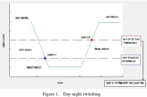
Infra-red light also counts into the luminance. If left alone, when luminance drops to certain point and switch to night mode, the activated infra-red light will increase the luminance back and possibly cause the camera to immediately switch back to day mode (Fig. 1). Therefore luminance alone cannot solve the issue and another method to classify day and night image is necessary. This is one of the reasons why day to night and night to day switching is separated.
Figure 1. Day-night switching
For this purpose security camera company usually used extra sensor and alogrithm. Such as, Bosch Security Systems add an extra sensor called Ambient Light Sensor (ALS) which always filter infra-red light even in night mode. ALS is often use for a light sensor from the environment such as on [1] and [2]. However, this solution has its own weakness. ALS and the image sensor have a different field of view because they are a separate sensor.
The final product will be a prototype application which will have a night to day switch algorithm implemented and is able to communicate with a camera to receive data and send commands to the camera using a library provided by the company. The goal of the research is to develop a night to day switching algorithm without using ALS and implement it in a prototype application (Fig. 2).
Figure 2. Research Development
II. PROCESS ANDRESULT A. Gathering Data from Camera
Gathering data from the cameras is the first step in offline development. In order to look at the cameras’internal data, a debug page can be accessed via http protocol of the IP-based cameras. To collect data, a logging tool must be developed to process the data in the debug pages into log files.
For the next step, a lot of log files need to be collected under many different scenes and camera settings. Bosch provides a light-room studio that allows someone to freely manipulate the light in the room and replicate both bright and dark scenes. To make process of gathering data easier, the logging tool is made to be able to integrate with the light-room studio lamp and control the light output.
The logging tool is developed in C# because of a few reasons:
• C# is for general purpose programming
• Libraries used to control light-room supports C#
• Project examples for the libraries are also in C#
First, we use a command line interface (CLI) program and a testing camera connect and create log files from camera’s internal data (Fig. 3). Then some important data such as R/G B/G ratio values [3] from the sensor, color temperature, color gains, integration time, and etc. Because of the image pipeline design [4], the full resolution of the picture’s data cannot be obtained, instead, the image is divided into 32 by 32 grid then summed up (so the result is data with 32x32 pixel).
Figure 3. Screenshot of camera logging tool and sample log files
B. Visualize Logged Data
The data gathered contain a bunch of numbers and some raw data which are obviously not very easy to read and understand. Therefore, the data are processed to show it in a more human-friendly way. MATLAB is chosen to visualize the data because:
• Optimized for matrix and statistic calculations
• Able to display 2D and 3D plots without external plugins
• Able to create graphical user interface (GUI)
The main focus of the visualization is the red, green, and blue (RGB) [5] values. To visualize RGB values in 2D plot, both red and blue values are divided by green value, which results B/G as X-axis and R/G as Y-axis. This plot allows the RGB color distribution to be observable.
C. Data Behavior
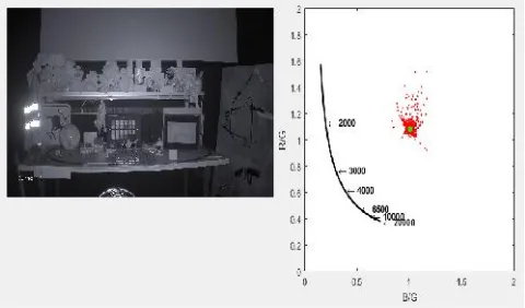
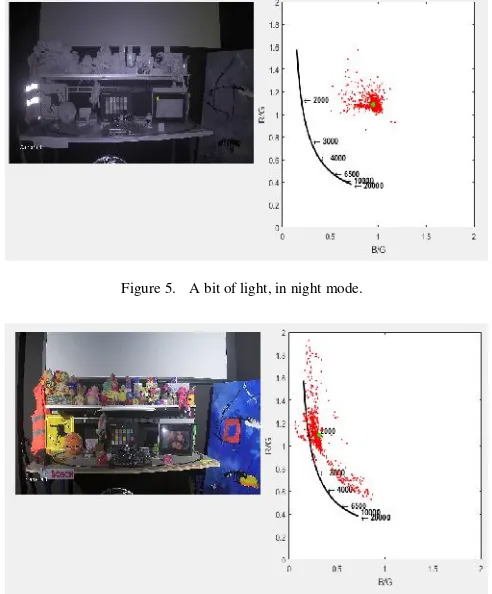
After the data have been gathered and visualized, the data can be observed and analyzed for any pattern or behavior that can be used in night to day switching. By observing the R/G B/G plots (as can be seen on Fig. 4, 5, and 6), these pattern are found:
Figure 5. A bit of light, in night mode.
Figure 6. Enough light, in night mode.
So we could conclude that R/G values will disperse and B/G values generally decrease as the scene gets brighter.
D. Determine Measurement
Although a behavior pattern is found, it needs to be processed into numerical value to represent day or night conditions. As show on Fig. 3, which contains pure infra-red light, the R/G and B/G values are accumulating around one point. If a region around that point is not counted toward scene luminance calculation, it is possible to have a value that can indicate day or night condition.
Figure 7. Region of Interest (ROI)
This value is called ambient sum, which is calculated by totaling the amount of green intensity of pixels that has R/G and B/G values outside the defined region, which is called Region of Interest (ROI), as seen on Fig 7. Only green values are counted into the total because of a few reasons:
• In scene luminance calculation, green’s weight significantly more than other colors:
R : G : B = 1 : 4.5907 : 0.0601 (1)
• Reduce processing load, which is important later on when implemented in the camera
E. Switching Condition
After the measurement to determine day or night condition (ambient sum) is determined, next the switching point also needs to be determined. Once ambient sum rise past the switching point (threshold), then the cameras should switch to day mode. Ambient sum is actually affected by camera settings, especially:
• Infra-red LED intensity
• Automatic Level Control (ALC)
• Exposure / Shutter time
Because the value of ambient sum changes along with the camera settings, the threshold must also adapt. Therefore threshold is formulated as follows:
Threshold = L norm x IR m x ALC m x Exposure m (2)
L norm = Base static value
Exposure m = Exposure multiplier. Based on current shutter time setting
The multiplier is calculated based on the 3 points which will be interpolated between each other using linear interpolation. The multiplier value is dependent to its respective settings (e.g. ALC multiplier is dependent to current ALC setting). These 3 points and L norm are tunable, which means it is set by user to allow the algorithm to adapt and suit as desired. It is not recommended to use more complicated interpolation or curve, as it will add more computation load when implemented into the camera.
F. Prototyping
This is the start of online development. The prototype needs to have these following functionalities:
• Connect to camera and receive data
• Calculate measurement
• Execute night to day switching
The main application is built on MATLAB, which will handle the GUI and the calculation. Connecting to camera and receive the data is done by C# application derived from the logging tool and integrated to the MATLAB application. Executing the night to day switching is done by third party application called Metis. Metis is application developed by Bosch for internal use, mainly used to read and write the cameras’ registry.
Additionally, the prototype application has timeout and sleep functionalities. Timeout is meant to prevent immediate oscillations of switching back to day mode after switching to night mode. This is because the cameras need a bit of time to adjust after switching modes. Sleep functionality is to avoid wasting resource to process the data while the camera is in day mode.
G. Testing
With the completion of prototype application, it is now possible to test and compare it with ALS. The comparison is done by getting the switching point of the two night to day switching mechanism and compare the result. The target of the new algorithm is to get values as close as possible to the values from ALS.
Because the way of the two algorithm operate is different, it is expected to have some difference, hence 100% accuracy is not possible. Thus, the comparison is done using mean squared error [6] and absolute error method [7]. Both are methods to measure how close the predicted/resulting values are compared to the target values.
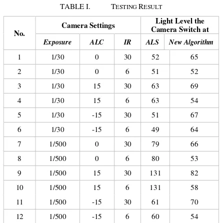
The resulting switching points shown in the table 1 are somewhat off the target. This is because the tuning values are not properly tuned yet. The values used are initial values which are based on only a few data samples. If desired, the experts in Bosch can change the tuning values themselves to get a better result from the prototype application.
TABLE I. TESTINGRESULT
No.
Camera Settings Light Level the Camera Switch at
Exposure ALC IR ALS New Algorithm
1 1/30 0 30 52 65
a.Light level are based on the output level of light-room studio lamp
b.Only one type of light is used (white light)
% Mean Squared Error = 15.2% % Absolute Error = 10.8%
Overall, the result is acceptable because there is no oscillation problem and the computation is not too tasking. It can be concluded that the developed algorithm is definitely a viable option for night to day switching mechanism.
III. CONCLUSION ANDRECOMMENDATION
In conclusion, the algorithm developed is capable of determining when to switch from night mode to day mode. The result shows that it is possible to do night to day switching without relying on ALS and only use camera’s internal data. The algorithm makes use of color distribution and RGB intensity to measure the ambient light. In addition, the algorithm can be adapted and flexible. The results can become even better by having the right tuning values.
There are some interesting things to note for future research. It is mentioned in previous chapter that the algorithm classification excludes scenes with both low ambient light and low IR light, which gives generally black images with lot of noises. For now, the problem can be avoided by having the right tuning values, but a more appropriate countermeasure may need to be researched further.
Overall, the project is successful and all of the objectives are achieved. The prototype application met the designed expectation and is able to fulfill all the required functionalities without any problem.
REFERENCES
[1] L. Schwittmann, C. Boelmann, V. Matkovic, M. Wander, T. Weis, “Identifying TV Channels & On-Demand Videos using Ambient Light Sensors,” Pervasive and Mobile Computing, Vol38, 2017, pp. 363–380, doi: 10.1016/j.pmcj.2016.08.018.
[2] J. Greena, H.P.Olivasa, S.M.Díazb, J.G.Márqueza, C.D. González, R.S.Montero, H. Guan, M. Rozenblat, S.Topsu, “VLC-beacon detection with an under-sampled ambient light sensor,” Optics Communications, Vol 397, 2017, pp. 122–128, doi: 10.1016/j.optcom.2017.04.014.
[3] TechTerms, “RGB (Red Green Blue) Definition,”[Online] Available: https://techterms.com/definition/rgb
[4] D. Lee and K.N. Plataniotis,“Lossless compression of HDR color filter array image for the digital camera pipeline,”Signal Processing: Image Communication, Vol 27, Issue 6, 2012, pp. 637-649, 10.1016/j.image.2012.02.017.
[5] Wikipedia, “Color image pipeline,” [Online] Available: https://en.wikipedia.org/wiki/Color_image_pipeline
[6] Gepsoft, “Mean Squared Error,” [Online] Available: http://www.gepsoft.com/gepsoft/APS3KB/Chapter09/Section2/SS10.ht m