PR ODUCTS HANDBOOK
Str uctural Steel
2006 Edition
PR ODUCTS HANDBOOK
Str uctural Steel
Continental Steel Pte Ltd
>
>>>
The Company
1
Profile
1
Services
2
Explanatory Notes
9
General information
9
Introduction
9
Materials - EN10025 : 2004 is the new European
10
standard for structural steel
History of the standard
10
The new standard EN 10025 : 2004
10
Grade designation systems
11
Grades, properties and nearest equivalents
13
Manufacturing tolerances
16
Comparison between general structural
17
steel specifications
Section Properties
18
Dimensional units
21
Mass and force units
21
Comparison Between Hot Finished and Cold Formed Hollow Sections
22
Introduction
22
Specifications
22
Manufacture of hollow sections
23
Section properties
24
Structural performance
25
Compression resistance
26
Web bearing and buckling
26
Tension, shear and bending
26
Summary
27
Fire resistance
27
Externally protected columns
27
Internally protected columns
28
Cost comparisons
28
Universal Beams and Columns
31
General
31
Rolling tolerances - EN 10034 : 1993
32
Metric sizes
34
Section sizes
57
Castellated Beams
58
Section sizes
58
Structural Tees
63
General
63
Metric sizes
64
Imperial sizes
68
Bearing Piles
77
General
77
Metric sizes
78
Imperial sizes
80
Hot Finished Ellipcon Sections
83
General
83
Ellipcon sections
84
Semi Ellipcon sections
85
Hot Finished Hollow Sections
87
General
87
Comparable specifications
87
Product specifications
88
Chemical composition
88
Mechanical properties
88
Tensile test
88
Charpy V-notch impact test
88
Manufacturing tolerances
89
Other specifications
90
Circular sections
91
Square sections
96
Rectangular sections
100
Cold Formed Hollow Sections
105
>>>>
Circular sections
108
Square sections
111
Rectangular sections
116
Channels
119
Rolling tolerances - EN 10279 : 2000
119
Tapered Flange
120
Metric sizes
120
Imperial sizes
121
Parallel Flange
124
Purlins
125
General
125
Introduction
125
Material specifications
125
Storage and handling
126
Holing and cleating for C Purlins
127
Plain Channels
129
Lipped Channels
130
High-Tensile Galvanised C Purlins
132
High-Tensile Galvanised Z Purlins
133
Angles
135
Rolling tolerances - EN 10056-2 : 1993
135
Equal Angles
136
Unequal Angles
138
Bars
139
Flat Bars
139
Square Bars
141
Deformed and Round Bars
142
Plates
143
Product specifications
143
Main specifications
143
List of standard specifications
144
Mild Steel Plates
148
Chequered Plates
149
Pipes
153
JIS G3452 (1988) SGP
153
BS 1387 (1985)
154
API 5L (1991) and ASTM A53 (1997)
156
Chemical composition
156
Mechanical properties
156
Section sizes
157
PU Steel Sheet Piles
169
Mechanical properties
169
Dimensions and sectional properties
169
Interlocking options
170
Dimensional tolerances
170
Handling holes and double piles
170
KSP Steel Sheet Piles
171
Mechanical properties
171
Dimensions and sectional properties
171
Interlocking options
172
Dimensional tolerances
172
Recommended maximum lengths for driving
172
KSP Straight Web Sections
173
Mechanical properties
173
Dimensions and sectional properties
173
Dimensional tolerances
174
Gratings
General
175
Sizes
175
Appendix
Continental Steel Pte Ltd
>
>>>
Note: Section tables are not numbered and put in the list, except from High-Tensile Galvanised C and Z Purlins, Mild Steel
Plates, Chequered Plates, API 5L (1991) and ASTM A53 (1997) pipes, Steel Sheet Piles to EN 10248:1996 and Other Steel
Sheet Piles.
Table 1 - EN 10025 : part 2 : 2004 Non-alloy structural steels
13
Table 2 - EN 10025 : part 3 : 2004 Normalised/normalised rolled
14
Table 3 - EN 10025 : part 4 : 2004 Thermo mechanically rolled
14
Table 4 - EN 10025 : part 5 : 2004 Structural steels with improved atmospheric
15
Table 5 - EN 10025 : part 6 : 2004 Flat products of high yield strength structural steels
15
Table 6 - Comparison between general structural steel specifications
17
Table 7 - Conditions for welding cold-deformed zones and adjacent material
25
Table 8 - Fire resistance: Cost comparison - universal columns vs. circular hollows
29
Table 9 - Fire resistance: Cost comparison - universal columns vs. rectangular hollows
29
Table 10 - Universal Beams and Columns: Standard specifications
31
Table 11 - Structural Tees: Standard specifications
63
Table 12 - Bearing Piles: Standard specifications
77
Table 13 - Hot Finished Hollow Sections: Comparable specifications
87
Table 14 - Hot Finished Hollow Sections: Mechanical properties
88
Table 15 - Hot Finished Hollow Sections: Manufacturing tolerances
89
Table 16 - Cold Formed Hollow Sections: Comparable specifications
105
Table 17 - Cold Formed Hollow Sections: Mechanical properties
106
Table 18 - Cold Formed Hollow Sections: Manufacturing tolerances
107
Table 19 - Purlins: Material specifications and tolerances
125
Table 20 - Purlins: Tolerances on length and thickness
126
Table 21 - High-Tensile Galvanised Purlins: Mechanical properties/Tolerances
126
Table 22 - High-Tensile Galvanised Purlins: Cleat holes position
128
Table 23 - High-Tensile Galvanised C-Purlins: Section sizes
132
Table 24 - High-Tensile Galvanised Z-Purlins: Section sizes
133
Table 25 - Plates: List of standards specifications
147
Table 26 - Plates: Sizes of Mild Steel Plates
149
Table 27 - Plates: Sizes of Chequered Plates
149
Table 28 - API 5L and ASTM A53 Pipes: Chemical composition
156
Table 29 - API 5L and ASTM A53 Pipes: Mechanical properties
156
Table 30 - PU Steel Sheet Piles: Section sizes
169
Table 31 - PU Steel Sheet Piles: Interlocking options
170
Table 32 - PU Steel Sheet Piles: Dimensional tolerances
170
Table 33 - KSP Steel Sheet Piles: Mechanical properties
171
Table 34 - KSP Steel Sheet Piles: Section sizes and properties
171
Table 35 - KSP Steel Sheet Piles: Interlocking options
172
Table 36 - KSP Steel Sheet Piles: Dimensional tolerances
172
Table 37 - KSP Straight Web Sections: Mechanical properties
173
Table 38 - KSP Straight Web Sections: Section sizes and properties
173
Table 39 - KSP Straight Web Sections: Interlocking strength
173
Table 40 - KSP Straight Web Sections: Dimensional tolerances
174
Purlins, Mild Steel Plates, Chequered Plates, API 5L (1991) and ASTM A53 (1997) pipes, Steel Sheet Piles to EN
10248:1996 and Other Steel Sheet Piles.
Figure 1 - Effect of cold working on material properties for cold formed hollow sections
24
Figure 2 - Comparison of corner radius of hot finished and cold formed hollow sections
24
Figure 3 - Compression/Slenderness curves for columns
26
Figure 4 - Universal Beams and Columns: Section shapes
31
Figure 5 - Structural Tees: Section shapes
63
Figure 6 - Bearing Piles: Section shape
77
Figure 7 - Twist of square or rectangular hollow sections
90
Figure 8 - How to measure cross-sectional dimensions of hollow sections
90
Figure 9 - C and Z Purlins
125
Figure 10 - Holing and cleats for C purlins
127
Figure 11 - PU Steel Sheet Piles: Dimensions
169
Figure 12 - KSP Steel Sheet Piles: Dimensions
171
Figure 13 - KSP Straight Web Sections: Dimensions
173
Being one of the biggest premier steel suppliers throughout the region, Continental Steel has the
first fully covered multi-storey warehouse that occupies a floor area of 350,000 sq. ft. The
ware-house has facilities that allows the following services:
a) Rust protected storage
b) Larger stockholding capacity that can accommodate 150,000 tons of material
c) 24 heavy-duty over-head cranes remotely controlled, some of which are magnetic
d) Ability to service 12 container trucks at any one time
e) Advanced handling system ensures quick delivery and turn around time
f)
Conducive working environment for more productive workforce in rain or shine
g) Ability to operate 24hr shifts to meet extra large quantity deadlines.
Continental Steel Pte Ltd is a CIDB registered supplier in the L5 category for all structural steel
The Company
○○○○○○○○○○○○○○○○○○○○○○
○○○○○○○○○○○○○○○○
○ ○ ○ ○ ○ ○ ○ ○ ○ ○ ○ ○ ○ ○ ○ ○ ○ ○ ○ ○ ○ ○ ○ ○ ○ ○ ○ ○ ○ ○ ○ ○ ○ ○ ○ ○ ○ ○ ○ ○
Apart from being the supplier of a comprehensive range of
quality steel sections, Continental Steel aims to extend its
commitment to customers by enhancing its services and adding
new facilities. A dedicated team is tasked to provide technical
support so as to advise the proper usage of steel and assist
With a new team of highly qualified
engineers we can advise our customers
on the correct use of structural steel and
provide help on the structural design.
•
Shearing of steel plate
Shearing facility that sizes steel plates up to
20mm thickness and maximum 6.1m width.
operations
In current competitive business environment,
efficiency and product specialization are the
essence to a business survival and profitability.
So for building contractors and developers,
material usage control and wastage management
plus other fixed overhead investments like
machinery and work-shop space should be kept
at a minimum level. To meet this demand we had
invested both machinery, skill workers and other
infra-structure to provide cut to size and bend to
shape reinforcement bars services. Thus
removing building contractors and developers
tons of on-site work. Our company is also a HDB
approved cut and bend service provider.
Dimensions and bend angles checks are part of
the work process to ensure the end product meet
customers' requirement. All bending activities are
either fully automatic or machines assisted.
Optimal layout of bending machines provides
valuable space for storing finished products.
Furthermore it provides capacity to bend bars up
to 12 meters length.
Thus out-sourcing cut and bend activities by
contractors and developers assist them in
managing their resources far more efficiently and
effectively.
•
CNC Drilling &
Bandsawing Line
System
range of material requirements.
KD series have two horizontal and one vertical
axis drill spindle, with a maximum drill capacity of
40 mm and are fitted as standard with an auto
tool changer.
Features of the KD machine:
- Machine gantry designed with robust
welded construction
- Programmed spindle speeds are
automatically assigned to each
drill diameter
- Automatic drill offset by touch sensing of
the drill tips against the material
- Lowering program for all three drill bits
- Electro-mechanical drill feed using ball
bearing spindle with servo motor
- Automatic cross-section measuring
- Fast and precise drill spindles positioning
via ball screw drive and servo motors.
ensures a fast and easy programming of the
machine.
Working Range and Technical Data:
Angle steel max (mm)
250 x 250 x 28
U Steel max(mm)
400 x 110
H beam max (mm)
1,000 x 400
Drilling unit:
Vertical (Y-axis) (pc)
1
Horizontal (Z- and W-axes)(pc)
2
Future expansion of new drilling technology will
satisfy steel industry with advanced bolt
connection for structural steel work industry. A
new Thermal Friction Drilling system will bush
length up to 3 times the original thickness. This
system produces perfectly formed bushes using
a combination of rotation speed and pressure to
locally heat the material, forming a bush in various
thickness of metal.
The Band saw KBS 1001 DG was developed for
the special requirements of steel construction and
steel suppliers and combine solid machine
construction with high performance elements. The
large cutting range, even for acutely angled
mitre-squares on both sides, combined with compact
construction, particularly distinguish this Bandsaw.
A Hydraulic saw band feed, infinitely variable at
the freestanding control cabinet (feed control by
proportional valve technology) and a 7.5 KW
strong drive motor with infinitely cutting speeds
ensures perfect cutting performance.
F
eatures of the KBS Bandsaw:
-
Short setup times due to NC-controlled
mitre angle setting and automatic cycle
control (clamping - sawing- releasing)
-
Enhanced band life thanks to full-stroke
hydraulic band tensioning with auto
stand-by tension feature, plus coolant
atomizer system.
-
Secure material clamping via
self-adjusting machine vise.
-
Coolant Atomizer System for efficiently
lubrification and cooling of the
sawband.
Via the graphical user surface Proficut, running
under Windows, the machine could be
programmed. The software is able to import DSTV
or CSV files from customers' software.
way and material handling equipment. With a
uniform control, Continental can achieve the
optimum production environment
In concert with our Quality Assurance program
and continuous inspection control, we are in the
edge in providing best flexibility, productivity and
reliability of steel saw and drill service. We
welcome the challenge to become your supplier
of high quality ready-to-use steel products to be
delivered on time.
Bundles:
90
°
mm
600 x 500
Square
90
°
mm
1,000 x 500
Beams
45
°
mm
640 X 500
30
°
mm
400 x 500
Mitre Cutting range
degrees 45 - 90 - 30
Technical data:
Band dimensions
mm
8,250 x 54 x 1.6
Drive capacity
KW
7.5
•
Auto shot blasting and
painting
For better steel finishes and protection, the fully
automatic shot blasting machines attend to the
steel treatment needs with the provision of
in-house painting.
•
Fully computerised
administrative system
Computer networks that ensure quicker and more
efficient administration fully support the office
procedures from quotations to delivery.
•
Galvanising
Hot dip galvanising provides the permanent good
appearance and freedom from maintenance that
ensures long service life.
•
In house delivery service
Having a highly motivated team of delivery staff
and efficient transportation services, just in time
requirements can be achieved. There are 24
heavy-duty over-head cranes remotely controlled,
some of which are magnetic with up to 12 tons
loading capacity. A mobile crane with maximum
30 tons lifting capacity is also available to ensure
unloading at any construction site.
General information
All weights and measures shown on invoices will be governed by standards of the
respective specifications so offered.
Care has been taken to ensure that all data and information herein are factual and that
numerical values are accurate. To the best of our knowledge, all information contained
in this handbook is accurate at the time of publication. Continental Steel Pte Ltd
assumes no responsibility for errors in or misinterpretation of the information contained
in this handbook or in its use.
Introduction
To serve the increasing demands for more section types and to create the awareness on the
proper use of steel, we have come up with a new product catalogue. The new handbook has a
more comprehensive range of products and useful technical information, and it also functions
as a design reference for the consultants and a product catalogue for our customers.
To help our customers to proper design and use of steel we have also extended the business by
offering our customers technical support from our team of Structural Engineers.
The catalogue contains up-to-date materials standards specifications.
Note that new European standards supersede most of the old British Standards, see sections
“Materials” and “Manufacturing tolerances” under this chapter, and the design guide BS 5950
substitutes BS 449.
The content list of our new catalogue shows that we have increased the range of section types
and sizes. This is to give our customers a bigger choice when selecting material and more room
for imagination, innovation and flexibility when designing and planning for new structures.
With more sections to choose from, the designers will have opportunities to make better and
more cost efficient designs, by selecting the section size closest to that required.
Some of the new section types we have added to our product list are:
Structural Tees
Cellular Beams
Hot Finished Ellipcon Sections, elliptical and semi elliptical
Parallel Flange Channels
High-Tensile Galvanised C and Z Purlins.
The new catalogue also contains a comparison between hot finished and cold formed hollow
sections. We included this because substitution of cold formed sections for hot finished sections
are very common in this region, but not everybody knows the differences between the two
section types.
The first few pages of the catalogue give a short resume of the company profile and the services
we provide. The summary shows that we have extended our business by adding more value to
the steel we supply to our customers.
EN 10025 : 2004 is the new European standard for structural steel. It shows the new grades,
properties and the nearest equivalent grades from former standards including EN 10025 : 1993.
The grade designation system is also explained.
History of the standard
The European Committee for Iron and Steel Standardisation is responsible for producing the
European Standards (ENs) for structural steels. The first of these standards, EN 10025, was
published in the UK by BSI as EN 10025 : 1990, partly superseding BS 4360 : 1986, which was
re-issued as BS 4360 : 1990. In 1993, a second edition of EN 10025 was made available together
with EN 10113 : parts 1, 2 & 3 and EN 10155. In June 1994, EN 10210 : part 1 was published and
at the same time BS 4360 was officially withdrawn. The balance of the BS 4360 steels not affected
by these ENs were re-issued in new British Standards BS 7613 and BS 7668. In 1996, with the
publication of EN 10137, BS 7613 was withdrawn. BS 7668 will remain until an EN for atmospheric
corrosion resistant hollow sections is available
In 2004 the standard EN 10025 was revised to address the provisions of EU Construction Products
Directive (89/106/EEC). It is now published in six parts to bring together almost all the 'Structural
Metallic Products' into one comprehensive standard.
The new standard EN 10025 : 2004
The new standard is published in six parts and draws together earlier standards to produce one
standard for the majority of structural steel products. The parts are:
• Part 1 - General technical delivery conditions.
• Part 2 - Technical delivery conditions for non-alloy structural steels.
Supersedes EN 10025 : 1993
• Part 3 - Technical delivery conditions for normalised / normalised rolled weldable fine
grain structural steels. Supersedes EN 10113 : parts 1 & 2 : 1993
Grade designation systems
The designation systems used in the new standard are similar but not identical to EN 10025 :
1993 and very different to the familiar BS 4360 designations so the guide below has been
prepared to assist purchasers, specifiers, designers and users of steel.
Symbols used in EN 10025 : part 2 : 2004 Non-alloy structural steels
S...
Structural steel
E...
Engineering steel
.235...
Minimum yield strength (Reh) in MPa @ 16mm
...JR..
Longitudinal Charpy V-notch impacts 27 J @ +20
°
C
...J0..
Longitudinal Charpy V-notch impacts 27 J @ 0
°
C
...J2..
Longitudinal Charpy V-notch impacts 27 J @ -20
°
C
...K2..
Longitudinal Charpy V-notch impacts 40 J @ -20
°
C
...+AR
Supply condition as rolled
...+N
Supply condition normalised or normalised rolled
Customer options
...C..
Grade suitable for cold forming
...Z..
Grade with improved properties perpendicular to the surface
Examples: S235JR+AR, S355K2C+N
Symbols used in EN 10025 : part 3 : 2004
Normalised/normalised rolled weldable fine grain structural steels
S...
Structural steel
.275...
Minimum yield strength (Reh) in MPa @ 16mm
...N..
Longitudinal Charpy V-notch impacts at a temperature not lower than -20
°
C
...NL..
Longitudinal Charpy V-notch impacts at a temperature not lower than -50
°
C
Customer options
...Z..
Grade with improved properties perpendicular to the surface
Examples: S275N, S420NL Z35
Symbols used in EN 10025 : part 4 : 2004
Thermo mechanically rolled weldable fine grain structural steels
S...
Structural steel
.275...
Minimum yield strength (Reh) in MPa @ 16mm
...M..
Longitudinal Charpy V-notch impacts at a temperature not lower than -20
°
C
...ML..
Longitudinal Charpy V-notch impacts at a temperature not lower than -50
°
C
Customer options
...Z..
Grade with improved properties perpendicular to the surface
S...
Structural steel
.355...
Minimum yield strength (Reh) in MPa @ 16mm
...J0..
Longitudinal Charpy V-notch impacts 27 J @ 0
°
C
...J2..
Longitudinal Charpy V-notch impacts 27 J @ -20
°
C
...K2..
Longitudinal Charpy V-notch impacts 40 J @ -20
°
C
...W..
Improved atmospheric corrosion resistance
...P..
Greater phosphorus content (grade S355 only)
...+AR
Supply condition as rolled
...+N
Supply condition normalised or normalised rolled
Customer options
...Z..
Grade with improved properties perpendicular to the surface
Examples: S235J0W+AR, S355K2W+N Z25
Symbols used in EN 10025 : part 6 : 2004 Flat products of high yield strength
structural steels in the quenched and tempered condition
S...
Structural steel
.460...
Minimum yield strength (Reh) in MPa @ 16mm
...Q..
Longitudinal Charpy V-notch impacts at a temperature not lower than -20
°
C
...QL..
Longitudinal Charpy V-notch impacts at a temperature not lower than -40
°
C
...QL1.. Longitudinal Charpy V-notch impacts at a temperature not lower than -60
°
C
Customer options
...Z..
Grade with improved properties perpendicular to the surface
Notes
1
For all products to be compliant with the EU Construction Products Directive (CPD 89/106/EC) the material
must offer a guaranteed minimum impact performance. This has resulted in the removal of this grade from the
standard, and the lowest grade now offered is the JR version for each yield strength variation.
2
Verification of the specified impact value is only carried out when agreed at the time of the enquiry and order.
Grades, properties and nearest equivalents
The tables below show the grades, properties and nearest equivalent grades from
earlier standards. The grade designations are explained on the previous pages.
Comparison between grades in EN 10025 : part 2 : 2004 and nearest equivalent versions in EN 10025 : 1993 and BS 4360 : 1990
EN 10025 : part 2 : 2004 EN 10025 : 1993 BS 4360 : 1990
Grade Yield (Reh) min Tensile (Rm) Charpy V-notch longitudinal
Strength at t = 16mm (MPa) Temp (oC) Energy (J) t =16mm
Grade Grade
S185 185 290/510 - - S185 -
-1 - - S235 40A
S235JR2 20 27 S235JRG1/G2 40B
S235J0 0 27 S235J0 40C
S235J2
235 360/510
-20 27 S235J2G3/G4 40D
-1 - - S275 43A
S275JR2 20 27 S275JR 43B
S275J0 0 27 S275J0 43C
S275J2
275 410/560
-20 27 S275J2G3/G4 43D
-1 - - S355 50A
S355JR2 20 27 S355JR 50B
S355J0 0 27 S355J0 50C
S355J2 -20 27 S355J2G3/G4 50D
S355K2
355 470/630
-20 40 S355K2G3/G4 50DD
E295 295 470/610 - - E295 -
S335 335 570/710 - - S335 -
E360 360 650/830 - - E360 -
1 MPa = 1 N/mm2
EN 10025 : part 3 : 2004 EN 10113 : part 2 : 1993
BS 4360 : 1990
Grade Yield (Reh) min Tensile (Rm) Charpy V-notch longitudinal Grade Grade
Strength at t = 16mm (MPa) Temp (oC) Energy (J) t =16mm
S275N -20 40 S275N 43DD
S275NL
275 370/510
-50 27 S275NL 43EE
S355N -20 40 S355N 50
S355NL
355 470/630
-50 27 S355NL 50EE
S420N -20 40 S420N -
S420NL
420 520/680
-50 27 S420NL -
S460N -20 40 S460N 55C
S460NL
460 550/720
-50 27 S460NL 55EE
1 MPa = 1 N/mm2
Table 2 –
EN 10025 : part 3 : 2004 Normalised/normalised rolled
weldable fine grain structural steels
Comparison between grades in EN 10025 : part 4 : 2004 and nearest equivalent versions in EN 10113 : part 3 : 1993
EN 10025 : part 4 : 2004 EN 10113 : part 3
:1993 Grade Yield (Reh) min Tensile (Rm) Charpy V-notch longitudinal
Strength at t = 16mm (MPa) Temp (°C) Energy (J) t = 16mm
Grade
S275M -20 40 S275M
S275ML 275 370/510 -50 27 S275ML
S355M -20 40 S355M
S355ML 355 470/630 -50 27 S355ML
S420M -20 40 S420M
S420ML 420 520/680 -50 27 S420ML
S460M -20 40 S460M
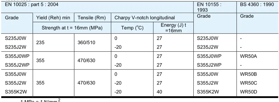
Comparison between grades in EN 10025 : part 5 : 2004 and nearest equivalent versions in EN 10155 : 1993 and BS
Table 4 –
EN 10025 : part 5 : 2004 Structural steels with improved atmospheric
corrosion resistance - also known as weathering steels
Comparison between grades in EN 10025 : part 6 : 2004 and nearest equivalent versions in EN 10137 : part 2 : 1996 and BS 4360 : 1990
Table 5 –
EN 10025 : part 6 : 2004 Flat products of high yield strength structural steels
in the quenched and tempered condition
Note
EN 10149 (1995/1996)
: “Hot-rolled flat products made of high yield strength steels for cold forming”
#
EN 10210 -Part 1 (1994)
: "Hot finished structural hollow sections of non-alloy and fine grain
structural steels"
EN 10219 -Part 1 (1997)
: "Cold formed welded structural hollow sections of non-alloy and fine
grain steels"
SS104 (1996)
: "Cold formed steel sections for general structures"
Some of the standards mentioned above are new European standards superseding the old British
Standards BS 4360: “Weldable structural steels” (1986) and BS 6363:
“Welded cold formed steel structural hollow sections” (1983).
Material to other specifications such as ASTM, AS and JIS can also be supplied.
Manufacturing tolerances
The dimensions, mass and tolerances of the sections are generally as listed in the following standards:
BS 4 -Part 1 (1993)
: "Structural Steel Sections" for hot rolled universal beams and columns and
tees cut therefrom, channels, bearing piles and rolled tees
#
EN 10029 (1991)
: “Specifications for tolerances on dimensions, shape and mass for hot rolled steel
plates 3mm thick or above”
EN 10034 (1993)
: “Structural steel I and H sections - Tolerances on shape and dimensions”
EN 10051 (1992)
: “Continuously hot-rolled uncoated plate, sheet and strip of non-alloy and alloy
steels - Tolerances on dimensions and shape”
EN 10056 -Part 2 (1993)
: "Structural steel equal and unequal leg angles -Tolerances on shape and
dimensions”
#+
EN 10210 -Part 2 (1997)
: "Hot finished structural hollow sections of non-alloy and fine grain
structural steels"
EN 10219 -Part 2 (1997)
: "Cold formed welded structural hollow sections of non-alloy and fine
grain steels"
SS104 (1996)
: "Cold formed steel sections for general structures" for lipped channels
Some of the standards mentioned above are new European standards superseding the old British
Standards BS 4848 - Part 2: “Hot-rolled structural steel sections - Hot-finished hollow sections”
(1991) and BS 6363: “Welded cold formed steel structural hollow sections” (1983).
In the section “Comparison between hot finished and cold formed hollow sections” we have explained
the differences between the two sections, and why cold formed sections can not be used to substitute
hot finished sections without rechecking the capacity.
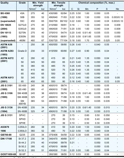
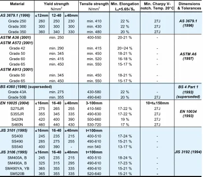
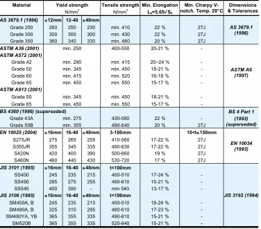
Comparison between general structural steel specifications
The following specifications are normally readily available, but offers depend upon acceptance of full
specification details or specifications not listed below.
Table 6 – Comparison between general structural steel specifications
Quality Grade Min. Yield
Notes: For BS, EN and JIS the values are for sections with thickness less than 16mm.
The followings are taken from EN 10210-2 (1997), EN 10219-2 (1997) and BS5950 Volume
1 Design Guide, 5th edition 1997
Corner radius ( r )
For hollow sections the corner radius are taken from EN 10210 and EN 10219, for hot
finished hollow sections and cold formed hollow sections respectively.
For hot finished square and rectangular hollow sections:
Nominal external corner radius for calculation is
r
o=1.5T
Nominal internal corner radius for calculation is
r
i=1.0T
For cold formed square and rectangular hollow sections:
Nominal external corner radius for calculation is
For thickness T
6mm:
r
o=2.0T
For thickness 6mm < T
10mm:
r
o=2.5T
For thickness T > 10mm:
r
o=3.0T
Nominal internal corner radius for calculation is
For thickness T
6mm:
r
i=1.0T
For thickness 6mm < T
10mm:
r
i=1.5T
For thickness T > 10mm:
r
i=2.0T
For other section types the manufacturers are using rules from various standard
specifications, which will take too much space to include in this handbook. Refer to the
respective country’s standards.
Second moment of area ( I )
The second moment of area of the section, often referred to as moment of inertia, has
been calculated based on first principal, by taking into account all tapers, radii and
fillets of the sections.
Radius of gyration ( r )
The radius of gyration is a parameter used in buckling calculation and is derived as
follows:
r
=
I
Elastic Modulus ( Z )
The elastic modulus is used to calculate the moment capacity based on the design
strength of the section or the stress at the extreme fibre of the section from a known
moment. It is derived as follows:
Z
I
y
=
where
y
is the distance to the extreme fibre of the section from the elastic neutral axis
and
I
is the second moment of area.
For castellated sections the elastic modulus given are those at the net section.
For channels the modulus about the minor axis (y-y) is given at the toe of the section.
For angles the elastic modulus about both axes are given at the toes of the section.
Plastic Modulus ( S )
The plastic modulus is calculated based on the first principal, by taking moment about
the equal area axis. Only the full plastic modulus (S) is given in the tables. When a
member is subject to both axial load and bending, the plastic modulus must be
reduced to take account of the reduction in plastic moment of resistance. The details
for the reduction are given in BS 5950.
Buckling parameter ( u ) and torsional index ( x )
The buckling parameter and torsional index used in buckling calculations are derived
as follows:
For bi-symmetric flanged sections and flanged sections symmetrical about the minor
axis only:
For flanged sections symmetric about the major axis only:
u
I
S
S
x= is the plastic modulus about the major axis
=
1
I
I
yx
I
x= is the second moment of area about the major axis
I
y= is the second moment of area about the minor axis
A
= is the cross-sectional area
h
= is the distance between the shear centres of flanges (for T sections, h is the
distance between shear centre of the flange and the toe of the web)
H
= is the warping constant
derived as given below.
Because this value is very small, it is not tabulated.
The warping constants (H) for I, H and channel sections are calculated using the
formulae given in the SCI publication (P057)
Design of Members Subject to Combined
Bending and Torsion
.
Torsion constant ( J )
For Tee sections cut from UB and UC sections,
the torsion constant (J) has been
derived as given below.
(
)
The torsion constants (J) for I, H and channel sections are calculated using the
formulae given in the SCI publication (P057)
Design of Members Subject to Combined
Bending and Torsion
.
For circular hollow sections:
J
=
2
I
For square and rectangular hollow sections:
Torsion modulus constant ( C )
For circular hollow sections:
C
=
2
Z
where Z is the elastic modulus.
For square and rectangular hollow sections:
C
J
t
k
t
=
+
The dimensions of sections are given in millimetres (mm) and the calculated properties (centroidal
distances, cross-sectional areas, radii of gyration, moments of inertia, elastic and plastic modulus)
are given in centimetre (cm) units. Surface areas are in square centimetres (cm
2). Some of the
sections have imperial sizes but the dimensions and sectional properties for these sections are
given in the metric system.
The units for force, mass and acceleration are those of the Systeme International (SI). They are the
Newton (N), the kilogram (kg) and the metre per second per second (m/s
2) so that 1N=1kgx1m/s
2.
The acceleration due to gravity varies slightly from place to place and for convenience a "standard"
value of 9.80665 m/s
2has become generally accepted in structural engineering. With this
convention, the force exerted by a mass of 1kg under the action of gravity is the "technical unit" of
9.80665N. In the same way 9.80665 kilo Newton is the force exerted by a mass of 1 tonne
(1000kg) under gravity and 1kN the force from a mass of 0.102 tonne.
Dimensional units
Introduction
The objectives of the comparison are to gain an understanding on the differences between hot and
cold formed sections, and subsequently, correct applications of the sections.
Hot finished hollow sections have been successfully used in primary structures for many years, but
there is yet little experience with the use of cold formed sections. Cold formed products differ from
the hot finished in many respects. Therefore, their use in primary structures must be approached
with caution.
Thin walled cold formed open sections have been used in construction as secondary members,
such as purlins, for a long time. However, there is a growing trend of manufacturing thicker walled
cold formed hollow sections and the temptation to introduce them into primary structures.
Cold formed hollow sections produced to EN 10219 are suitable for structural use. However,
they should not be used as a direct substitute for hot finished hollow sections without
reconsideration of the design capacity.
With the implementation of the European Standard for cold formed structural hollow sections
-EN 10219 - there exists a situation of identical grade designations for the majority of the common
strength grades used in both the hot finished (EN 10210) and cold formed (EN 10219) standards.
For instance, sections with yield strength of 275 N/mm2 and Charpy impact strength of 27 Joules at
-20 degrees will have a grade designation of S275J2H in both standards.
Common designation can lead to direct substitution and interchanging of the sections. Since cold
formed sections generally are weaker than hot finished sections it is essential that products are
specified accurately.
If a full designation of the steel is given to include both the standard number and the grade/quality
of the steel, substitution of cold for hot finished sections can be prevented. For example, a hollow
section of yield strength 275N/mm2 and a Charpy impact strength of 27 Joules at -20 degrees
should be designated as EN 10210 S275J2H for hot finished and EN 10219 S275J2H for cold
formed sections.
Hot finished hollow sections
The manufacture of hot hollow sections involves a number of processes and cold forming may be
used initially. However, the hot finished product is characterised by the final forming operation, which
is always being carried out in the austenitic state (i.e. above 920 degrees).
As a result, the forming operations do not affect the physical properties of the final product, which are
uniform around the complete periphery, including the seam weld in continuously welded sections.
Cold formed hollow sections
The physical properties of the cold formed sections are significantly affected by the method used in
producing the strip, section forming processes and the final shape and dimensions of the resulting
section. The strip used for the cold formed sections may be hot or cold rolled.
Plastic deformation and straining occur during the cold forming operations mentioned below:
1) uncoiling of strips
2) strip flattening
3) forming into a round section
4) welding of round sections
5) circular sections formed into square or rectangle
6) straightening of the curved walls and corners formed
Note: Square or rectangular hollow sections are not necessarily formed from round sections, some
manufacturers form the square or rectangle directly from strip.
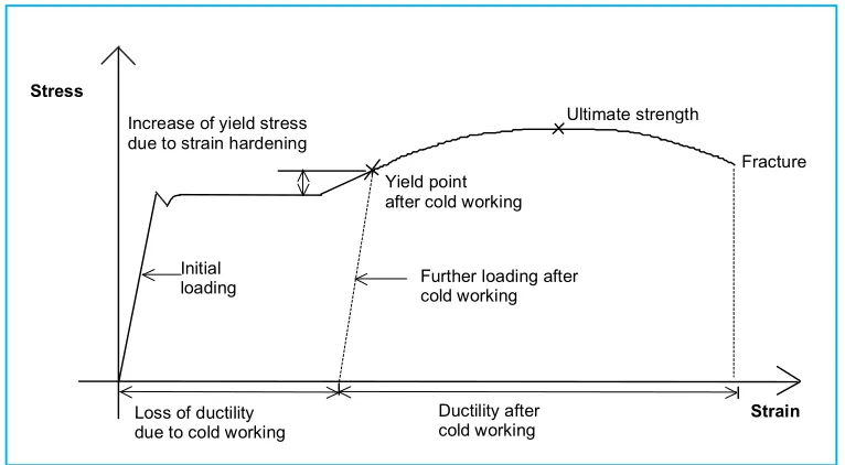
Cold forming is known to increase the yield and tensile strength of the materials due to cold working or
strain hardening (see Figure 1). However, as the strength increases, ductility decreases. And the
process may result in a section in which the strength and ductility vary considerably around the periphery.
For example, a test specimen from the flat face of the cold formed section will only indicate the conditions
applying to that face. There are also differences in the mechanical property transverse and longitudinally
on the section. Thus,
cold formed sections must be used with caution and proper design,
especially
in the use for primary structures.
There should be restrictions for the welding of cold formed sections. The corners of these sections are
subjected to high residual stress due to cold working. Welding further induces the residual stress at
the corners because of high local heating.Corner cracking occurs when the yield stress of these cold
formed sections is exceeded by the residual stress built up at the corners.
Cold formed welded structural hollow sections of non-alloy and fine grain steels
EN 10219-1 (1997):
Technical delivery requirements
EN 10219-2 (1997):
Tolerances, dimensions and sectional properties
BS 5950-1:
Structural use of steel works in building - Code of
practice for design of rolled and welded sections*.
*Subject to changes.
Design of cold formed hollow sections for primary structures will be included in the new BS 5950 Part 1, 1999/2000 (6th edition).
Figure 1 – Effect of cold working on material properties for cold formed hollow sections
Cold formed rectangular and square hollow sections have rounder corners than the hot finished
sections. This is to avoid corner cracking from occurring during the forming of cold formed sections,
because of too sharp corner radius or too thick sections.
However, the larger or rounder the corner radius, the smaller are the cross sectional area, moment
of inertia, section modulus and radius of gyration, etc. for a given size of section compared with a
similar hot finished section. Larger corner radii can make fabrication difficult and require additional
weld metal or profiling to produce the right fit-up. This is a problem particularly when connecting
one section to the face of another section of similar size (see Figure 2), and can also add to
fabrication costs.
Section properties
Stress
Strain
Ultimate strength Increase of yield stress
due to strain hardening
Yield point after cold working
Initial
loading Further loading after cold working
Fracture
Loss of ductility due to cold working
Maximum thickness (mm)
For cold formed sections in tension, the variation of strength around the section could lead to local
over-stressing, which together with the reduced ductility in cold formed sections could reduce the
capability of the sections to redistribute loads.
As local stress redistribution often occurs even in elastic design, the maximum value of yield/
tensile strength ratio should not exceed 80%. This limitation is incorporated in some standards
(extract from “Hot formed RHS winning on points” from British Steel).
The ductility and Charpy impact toughness for sections to EN 10219 are equivalent to hot finished
hollow sections to EN 10210.
For the classification of cross sections the limiting width to thickness ratio will need minor
adjustments to take into account the residual stresses in the section due to cold forming and the
ductility of the material.
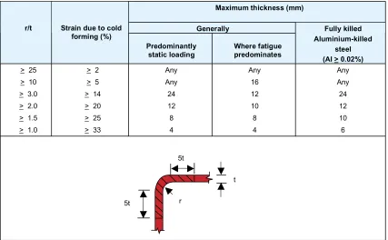
According to Europe Code 3 (ENV 1993-1-1:1992/A1:1994), welding of cold formed sections should
not be carried out in the cold deformed zones or within the adjacent width of 5t each side, see
Table 7, unless either:
-the cold-deformed zones are normalised after cold-forming but before welding;
-the thickness does not exceed the relevant value obtained from Table 7.
Due to stress relief effects, cold formed hollow sections are subject to greater distortion than hot
finished sections when subject to shot blasting, galvanising and welding. This can cause local
buckling, corner cracking and other deformations, and will obviously have a large impact on the
capacity when used as beams and columns.
Maximum thickness (mm)
Table 7 – Conditions for welding cold-deformed zones and adjacent material
5t
5t
t
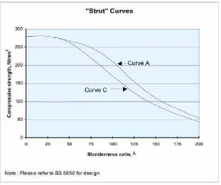
For compression members, the design strength should be based on the yield strength of the cold
finished section (as given in EN 10219) and not on that of the parent plate. Because of the lower
sectional properties and the residual stresses caused by the manufacturing process, a lower column
curve (curve C) is used for the cold formed sections compared to curve A for the hot finished sections.
This results in a larger reduction of the compression strength. Figure 3 shows the column curves.
Figure 3 – Compression/Slenderness curves for columns
"Strut" Curves
0 50 100 150 200 250 300
0 25 50 75 100 125 150 175 200
Slenderness ratio,
Compressive strength, N/mm
2
Curve A
Curve C
Note : Please refer to BS 5950 for design
Formulae for buckling and bearing for hot finished hollow sections can be found in the SCI Publication
Design Guide to the BS 5950: Part 1; Volume 1 Section Properties and member capacities and these
may also be used for cold formed sections (extract from New Steel Construction, August/September
1998).
Summary
Light gauge open cold formed sections have been widely used for secondary structures of
steel-framed buildings, such as purlins. Concern is however on the use of the cold formed hollow sections
for primary structures. For a cold formed hollow section of the same nominal size, thickness and
grade as a hot finished hollow section, the compression capacity dependent on the slenderness, can
be 34% lower than for the hot finished section.
The application of the current design rules on cold formed hollow sections might lead to optimistic
results, because the rounder corner radius for these sections can affect the “web” buckling
characteristics of the section.
Most design rules have restrictions on welding of cold formed sections due to the residual stresses
that occurs and to avoid corner cracking.
The advice is that there should not be direct substitution or interchanging of sections
without a capacity checking.
To avoid uncertified substitution the designers and quality surveyors have to know how to visually
differentiate cold formed and hot finished sections. A few things they should know are:
•
Because of the cold forming process the cold formed sections have a smoother, sometimes
oily surface, while the hot finished sections have a rougher surface.
If the sections are blasted or painted the corner radius and weld seam will indicate if the beam/
column is hot finished or cold formed.
•
As mentioned earlier the corner radius of cold formed sections are rounder than the corner
radius of hot finished sections.
•
The seam of welded cold formed sections are always on one of the flat sides, with a
distance from the corner, and on the same place for all members of the same bundle, but
for the hot finished sections the seam can be anywhere on the cross-section.
Fire resistance
There are several options to insure the fire resistance of steel structures. While hollow sections can
be protected on the inside, the outside or a combination of both, the universal columns can only be
protected on the outside.
Externally protected columns
For universal columns and
unfilled structural hollow sections
there are a number of ways to protect
Structural hollow sections
have the advantage that fire protection material like water or concrete,
can be
filled
inside the columns. It is very simple to design a hollow section with structural grade
concrete filling. First, the column is checked for room temperature loading, and then the fire resistance
is checked, if required, an external fire protection system is added. This method is very economic as
it both minimises the wall thickness of the hollow section, because of the concrete, and reduces the
thickness of the external protection system markedly below that of the unfilled section.
With use of concrete as internal protection of a
structural hollow section
, external protection
might not be necessary at all. The
concrete filling
will support the load when the temperature has
reached the point where the load bearing capacity of the steel is under the actual forces imposed on
the structure. The concrete core is designed to carry the whole of the load at the fire limit-state.
Plain concrete filling is suitable for mainly axially loaded columns, while bar reinforced concrete is
required for columns with significant moments.
For externally protected columns the composite concrete filled, intumescent-coated solution gives
the smallest required columns. While for the internally protected columns the bar reinforced concrete
filled solution gives the smallest footprint. Among all the four solutions the composite concrete filled,
intumescent-coated column gives the most economic solution.
Cost comparisons
British Steel in the United Kingdom has made a comparison between different types of fire protection
on hollow section columns and other steel sections. The study compared options for a typical
7-storey internal column carrying a loading of 6kN/m2 on a grid layout of 7.2 metres by 6 metres.
Where possible steel of design grade S355 was used, in general, this gives the most economical
solution for structural steelwork. In the case of internal protection, plain or bar reinforced concrete is
assumed. In the case of external protection, fire resistant boards were assumed for non-circular
columns, such as universal columns and rectangular/square hollow columns.
Three basic design options are possible for column design of structural hollow sections, and British
Steel looked at all 3 of them in this study.
Table 8 and Table 9 compares the costs of UC, CHS and RHS columns for various
methods of fire protection. Circled solutions are most economical.
Fire Protection Options CHS
External Board Intumescent Paint Internal Concrete Filling
Circular Hollow Sections Columns
Options UC Unfilled Composite Plain concrete Bar Reinforced
concrete
Option 1 100 111 88 134 88
Option 2 100 159 113 186 107
Option 3 100 111 97 186 107
Table 8 – Fire resistance: Cost comparison – universal columns vs. circular hollows
Fire Protection Options
RHS External Board External Board Intumescent
Paint
Internal Concrete Filling
Rectangular Hollow Sections Columns
Options UC Unfilled Composite Composite Plain concrete Bar Reinforced
concrete
Option 1 100 108 92 90 163 113
Option 2 100 111 121 115 231 123
Option 3 100 111 100 102 231 123
Universal Beams and Columns
General
The section sizes of universal beams and columns are given in the tables on the following pages.
We have split up the sections in metric and imperial sizes because the sections are rolled after
different standard specifications.
The tables cover I-beams, IPE- beams, H-beams and HE-beams. The difference between these
beams is that the H/HE-beams have wider flange than the I/IPE-beams and therefore look more like
the letter H than the letter I, see Figure 4. In our catalogue we put them all together to make it easier
to make the ultimate choice.
This European standard specifies tolerances
on shape dimensions and mass of structural
steel universal beams and columns. These
requirements do not apply to taper flange sections.
Section Height (h)
The deviation from nominal on section height
measured at the centre line of web thickness shall
be within the tolerance given in the following table.
Section Height h (mm) Tolerance (mm)
Up to and including 180 +3 -2 Greater than 180 up to and
including 400 +4 -2
Greater than 400 up to and
including 700 +5 -3
Greater than 700 +5 -5
Flange width (b)
The deviation from nominal on flange width
be within the tolerance given in the following
table.
Flange width b (mm) Tolerance (mm)
Up to and including 110 +4 -1 Greater than 110 up to and
including 210 +4 -2
Greater than 210 up to and
including 325 +4 -4
Greater than 325 +6 -5
Web thickness (s)
The deviation from nominal on web thicknes
measured at the mid-point of dimension (h)
be within the tolerance given in the following
table.
Flange thickness (t)
The deviation from nominal on flange thickness
measured at the quarter flange width point shall
be within the tolerance given in the following table.
Flange width (b)
The deviation from nominal on flange width shall
be within the tolerance given in the following table.
Web thickness (s)
The deviation from nominal on web thickness
measured at the mid-point of dimension (h) shall
be within the tolerance given in the following table.
Flange thickness s (mm) Tolerance (mm)
Less than 6.5 +1.5 -0.5
6.5 up to but excluding 10 +2.0 -1.0
10 up to but excluding 20 +2.5 -1.5
20 up to but excluding 30 +2.0 -2.0
30 up to but excluding 40 +2.5 -2.5
40 up to but excluding 60 +3.0 -3.0
60 and over +4.0 -4.0
h
x
x
d
s
y
b
r
Out-of-squareness (k + k')
The out-of-squareness of the section shall not
exceed the maximum given in the following table.
q
g
g
Section height h (mm) on length L (%) Greater than 80 up to
and including 180 0.30 L Greater than 180 up to
and including 360 0.15 L
Greater than 360 0.1 L Tolerance qxxor qyy
g
g
Flange width b (mm) Tolerance (mm)
Up to and including 110 1.5
Greater than 325
2% of b (maximum 6.5mm
Straightness (qxx or qyy)
The straightness shall comply with the requirements given
in the following table.
Tolerance on mass
The deviation from the nominal mass of a batch or a
piece shall not exceed
±
4.0%.
The mass deviation is the difference between the
actual mass of the batch or a piece and the calculated
mass. The calculated mass shall be determined using
a density of 7850kg/m3
Tolerance on length
The sections shall be cut to ordered lengths to
tolerances of
a.
±
50mm
or
b.+ 100mm where minimum lengths are requested
L represents the longest useable length of the section
assuming that the ends of the section have been cut
square.
Web off-centre (e) on mass
The mid-thickness of the web shall not deviate from
the mid-width position on the flange by more than
the distance (e) given in the following table.
Flange width b (mm)
Web off-centre where
e= (b1-b2)/2 T < 40
Up to and including 110 +4 Greater than 110 up to
and including 325 +4 T 40 Greater than 110 up to
and including 325 +4
Greater than 325 +6
b1
b2
COLUMNS
Depth Width Root Depth Area Size Mass Of Of Radius Between Of
Per Section Section Fillets Section End Metre Flange Web Flange Web Clearance
D B T t r d A b/T d/t C N n mm kg/m mm mm mm mm mm mm cm2
mm mm mm 100x50 9.30 100 50 7 5 8 70 11.8 3.57 14.0 5 33 15 100x100 14.8 100 100 7 5 10 66 19.2 7.14 13.2 5 58 17 16.9 100 100 8 6 8 68 21.6 6.25 11.3 5 57 16 17.2 100 100 8 6 10 64 21.9 6.25 10.7 5 57 18 125x60 13.2 125 60 8 6 9 91 16.8 3.75 15.2 5 37 17 125x125 23.6 125 125 9 6.5 8 91 30.0 6.94 14.0 5 69 17 23.8 125 125 9 6.5 10 87 30.3 6.94 13.4 5 69 19 150x75 14.0 150 75 7 5 8 120 17.8 5.36 24.0 5 45 15 150x100 20.7 148 100 9 6 8 114 26.3 5.56 19.0 5 57 17 21.1 148 100 9 6 11 108 26.8 5.56 18.0 5 57 20 150x150 31.1 150 150 10 7 8 114 39.6 7.50 16.3 6 82 18 31.5 150 150 10 7 11 108 40.1 7.50 15.4 6 82 21 37.4 154 151 12 8 11 108 47.7 6.29 13.5 6 82 23 175x90 18.0 175 90 8 5 8 143 22.9 5.63 28.6 5 53 16 18.1 175 90 8 5 9 141 23.0 5.63 28.2 5 53 17 175x125 23.3 169 125 8 5.5 12 129 29.7 7.81 23.5 5 70 20 175x175 32.8 171 174 9 6 12 129 41.7 9.67 21.5 5 94 21 40.2 175 175 11 7.5 12 129 51.2 7.95 17.2 6 94 23 40.4 175 175 11 7.5 13 127 51.4 7.95 16.9 6 94 24 200x100 17.8 198 99 7 4.5 8 168 22.7 7.07 37.3 4 57 15 18.2 198 99 7 4.5 11 162 23.2 7.07 36.0 4 57 18 20.9 200 100 8 5.5 8 168 26.7 6.25 30.5 5 57 16 21.3 200 100 8 5.5 11 162 27.2 6.25 29.5 5 57 19 200x150 29.9 194 150 9 6 8 160 38.1 8.33 26.7 5 82 17 30.6 194 150 9 6 13 150 39.0 8.33 25.0 5 82 22 36.9 198 151 11 7 13 150 47.0 6.86 21.4 6 82 24 200x200 41.4 196 199 10 6.5 13 150 52.7 9.95 23.1 5 106 23 49.9 200 200 12 8 13 150 63.5 8.33 18.8 6 106 25 57.8 204 201 14 9 13 150 73.6 7.18 16.7 7 106 27 65.7 208 202 16 10 13 150 83.7 6.31 15.0 7 106 29 250x125 25.1 248 124 8 5 8 216 32.0 7.75 43.2 5 70 16 25.7 248 124 8 5 12 208 32.7 7.75 41.6 5 70 20 29.0 250 125 9 6 8 216 37.0 6.94 36.0 5 70 17 29.6 250 125 9 6 12 208 37.7 6.94 34.7 5 70 21 250x175 43.6 244 175 11 7 13 196 55.5 7.95 28.0 6 94 24 44.1 244 175 11 7 16 190 56.2 7.95 27.1 6 94 27 51.6 248 176 13 8 16 190 65.7 6.77 23.8 6 94 29 59.1 252 177 15 9 16 190 75.3 5.90 21.1 7 94 31 250x250 66.5 248 249 13 8 16 190 84.7 9.58 23.8 6 131 29 71.8 250 250 14 9 13 196 91.4 8.93 21.8 7 131 27 72.4 250 250 14 9 16 190 92.2 8.93 21.1 7 131 30 98.1 260 253 19 12 16 190 125 6.66 15.8 8 131 35 300x150 25.0 294 148 6 4.5 16 250 32.6 12.3 55.6 4 82 22 Designation Thickness Ratios For Dimensions For Detailing
Notch Local