James Macfarlane
Network Routing Basics
Understanding IP Routing
James Macfarlane
Network Routing Basics
Understanding IP Routing
10475 Crosspoint Boulevard Indianapolis, IN 46256
www.wiley.com
Copyright © 2006 by James Macfarlane
Published by Wiley Publishing, Inc., Indianapolis, Indiana Published simultaneously in Canada
ISBN-13: 978-0-471-77273-6 ISBN-10: 0-471-77273-9
Manufactured in the United States of America 10 9 8 7 6 5 4 3 2 1
1MA/TQ/QT/QW/IN
No part of this publication may be reproduced, stored in a retrieval system or transmitted in any form or by any means, electronic, mechanical, photocopying, recording, scanning or otherwise, except as permitted under Sections 107 or 108 of the 1976 United States Copyright Act, without either the prior written permission of the Publisher, or authorization through payment of the appropriate per-copy fee to the Copyright Clearance Center, 222 Rosewood Drive, Danvers, MA 01923, (978) 750-8400, fax (978) 646-8600. Requests to the Publisher for permission should be addressed to the Legal Department, Wiley Publishing, Inc., 10475 Crosspoint Blvd., Indianapolis, IN 46256, (317) 572-3447, fax (317) 572-4355, or online at http://www.wiley.com/go/ permissions.
Limit of Liability/Disclaimer of Warranty:The publisher and the author make no representations or war-ranties with respect to the accuracy or completeness of the contents of this work and specifically disclaim all warranties, including without limitation warranties of fitness for a particular purpose. No warranty may be created or extended by sales or promotional materials. The advice and strategies contained herein may not be suitable for every situation. This work is sold with the understanding that the publisher is not engaged in ren-dering legal, accounting, or other professional services. If professional assistance is required, the services of a competent professional person should be sought. Neither the publisher nor the author shall be liable for dam-ages arising herefrom. The fact that an organization or Website is referred to in this work as a citation and/or a potential source of further information does not mean that the author or the publisher endorses the infor-mation the organization or Website may provide or recommendations it may make. Further, readers should be aware that Internet Websites listed in this work may have changed or disappeared between when this work was written and when it is read.
For general information on our other products and services or to obtain technical support, please contact our Customer Care Department within the U.S. at (800) 762-2974, outside the U.S. at (317) 572-3993 or fax (317) 572-4002.
Library of Congress Cataloging-in-Publication Data:
Macfarlane, James,
1953-Network routing basics : understanding IP routing in Cisco systems / James Macfarlane. p. cm.
"Wiley Technology Publishing."
Includes bibliographical references and index. ISBN-13: 978-0-471-77273-6 (cloth)
ISBN-10: 0-471-77273-9 (cloth)
1. TCP/IP (Computer network protocol) 2. Routers (Computer networks) I. Title. TK5105.585.M33 2006
004.6'2--dc22
2005035954
Trademarks:Wiley and related trade dress are registered trademarks of Wiley Publishing, Inc., in the United States and other countries, and may not be used without written permission. Cisco is a registered trademark of Cisco Systems, Inc. All other trademarks are the property of their respective owners. Wiley Publishing, Inc., is not associated with any product or vendor mentioned in this book.
James Macfarlane has worked in the personal computer and networking industry for over 20 years. He has worked in the capacity of consultant, net-work engineer, instructor, courseware developer, and technical writer.
Present and past certifications include Cisco CCNA, Microsoft MSCE and MCT, CompTIA A+ Trainer, and Novell CNE and CNI. James can be reached through his website at www.HotTrainingMaterials.com, and at
Technical Editor
Scott Bradneris the University Technology Security Officer at Harvard Uni-versity. Scott founded the Harvard Network Device Test Lab, is a frequent speaker at technical conferences, and a weekly columnist for Network World. Mr. Bradner has served in a number of roles in the IETF, and is currently a trustee of the American Registry of Internet Numbers (ARIN).
Acquisitions Editor Carol Long
Development Editor Kenyon Brown
Technical Editor Scott Bradner
Production Editor Felicia Robinson
Copy Editor Kathryn Duggan
Editorial Manager Mary Beth Wakefield
Production Manager Tim Tate
Vice President and Executive Group Publisher
Richard Swadley
Vice President and Executive Publisher
Joseph B. Wikert
Project Coordinator Ryan Steffen
Graphics and Production Specialists Denny Hager
Stephanie D. Jumper Alicia South
Quality Control Technicians Joe Niesen
Charles Spencer
Proofreading and Indexing Tammy Todd
Johnna Van Hoose
Credits
Acknowledgments xvii
Introduction xix
Chapter 1 Networking Overview 1
Chapter 2 Routing Basics 69
Chapter 3 Static Routing 89
Chapter 4 Dynamic Routing 103
Chapter 5 RIP 137
Chapter 6 IGRP 167
Chapter 7 EIGRP 185
Chapter 8 OSPF 221
Chapter 9 External Routing Protocols in Brief 343
Chapter 10 Redistribution and Default Routing 361
Appendix A Where Do You Go From Here? 379
Appendix B Recommended Reading 381
Appendix C RFCs Related to Routing 383
Appendix D Web References 387
Appendix E Administrative Distance Table 389
Appendix F Quick-and-Dirty Subnetting—No Calculator 391
Appendix G Subnetting Helper Sheet 393
Index 395
Contents at a Glance
Contents
xi
Acknowledgments xvii
Introduction xix
Chapter 1 Networking Overview 1
Overview 1
OSI Network Model 2
The Conundrum of Explaining the OSI Model 2
Mother of All OSI Model Explanations? 3
Anatomy of a Data Communication Session 3
The Way Things Used to Be 5
Explanation of OSI Layers 6
Another Mail Analogy 12
Encapsulation 13
TCP/IP Model 15
Networking Equipment 15
Packet Forwarding 16
Repeaters—Layer 1, Physical 16
Hubs—Layer 1, Physical 16
Bridges—Layer 2, Data-Link 17
Switches—Layer 2, Data-Link 18
Routers—Layer 3, Network 19
Layer 3 Switches 23
CSU/DSUs (TSU) 23
TCP/IP Review 24
IP Addressing 24
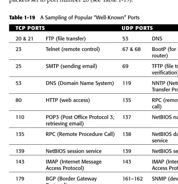
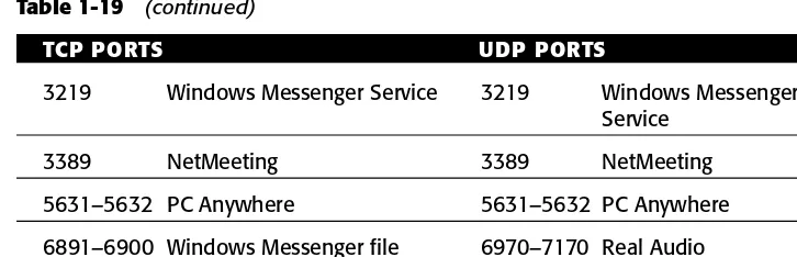
Ports and Sockets 56
Important Protocols Related to Routing 59
Chapter 2 Routing Basics 69
Overview 69
What Is Routing? 70
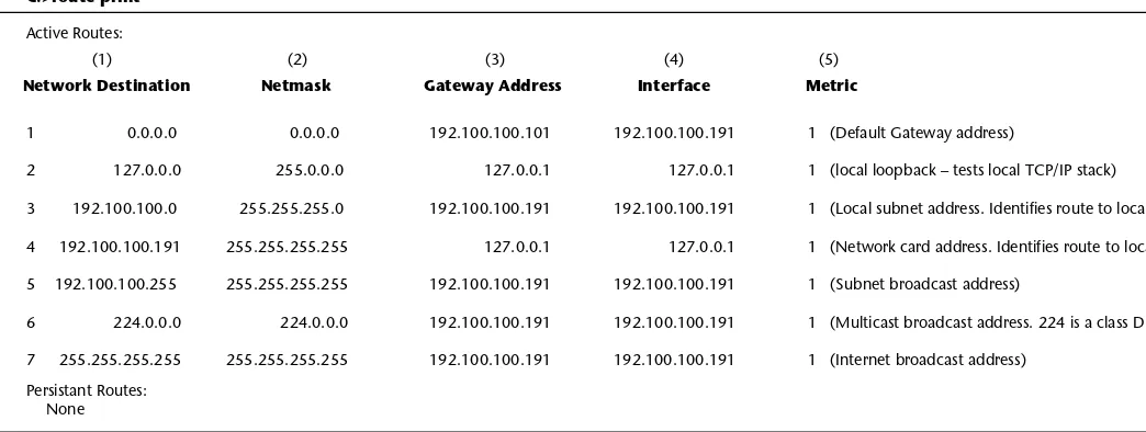
Routing Begins at Home—The Workstation’s Route Table 71
Row 1—Default Gateway 71
Row 2—Loopback Address 73
Row 3—Local Subnet Address 74
Row 4—IP Address of Host 75
Rows 5, 6, and 7—Broadcast Information 75
Anatomy of a Routed Packet 76
Track a Packet—Source and Destination on the Same Network 76 Track a Packet—Source and Destination on Different
Networks—One Router 78
Track a Packet—Source and Destination on Different
Networks—Multiple Routers 80
Anatomy of a Route Table 81
Key Concept for Understanding Route Tables 82
Populating Route Tables 83
Routing Metrics 84
Administrative Distance 84
Summary 86
Notes 88
Chapter 3 Static Routing 89
Overview 89
What Is Static Routing? 90
When to Use Static Routes 90
Configuring Static Routes on a Router 91
Example with a Small Routed Network 91
Static Routes on a Workstation 98
Floating Static Routes 100
Propagating Static Routes 101
Summary 101
Notes 101
Chapter 4 Dynamic Routing 103
Overview 103
The Need for an Automated Routing Solution 104
What Is a Routing Protocol? 105
Considerations for Designing Routing Protocols 106
Metrics of Routing Protocols 107
Categorizing Dynamic Routing Protocols 108
Interior versus Exterior Routing Protocols 108
Distance Vector versus Link-State 109
Singlepath versus Multipath 117
Contents xiii
Advantages of Using RIP 138
Disadvantages of Using RIP 138
RIP Background 139
Information that RIP Tracks About a Route 141
A Look at How Route Tables Are Populated by RIP 142
RIP’s Achilles Heel 145
RIP Timers that Contribute to Slow Convergence 145 How RIP Defends Itself Against the Dreaded Routing Loop 146
Anatomy of a Routing Loop 146
Measures to Prevent Routing Loops 149
Load Balancing 153
Show Commands for RIP 163
Troubleshooting Commands 164
Notes 165
Chapter 6 IGRP 167
Overview 167
Advantages of Using IGRP 168
Disadvantages to Using IGRP 168
Autonomous Numbers 173
Load Balancing in IGRP 173
Default Routing 174
Redistribution 175
Route Summarization in IGRP 175
Command Reference—IGRP 175
Initial Configuration 176
Common IGRP Commands 180
Show Commands for IGRP 182
Troubleshooting Commands 183
Notes 183
Chapter 7 EIGRP 185
Overview 185
Advantages of Using EIGRP 186
Disadvantages of Using EIGRP 187
EIGRP Background 187
EIGRP Terminology 187
Neighbor 188
Neighbor Discovery and Recovery 188
Packet Types 188
Hold-Time 188
Neighbor Table 189
Topology Table 189
Route Table 189
Reliable Transport Protocol (RTP) 189
Retransmission Timeout (RTO) 189
Smooth Round Trip Time (SRRT) 189
Reported Distance (RD) 189
Feasible Distance (FD) 189
Feasibility Condition (FC) 190
Successor 190
Feasible Successor (FS) 190
Diffusing Update ALgorithm (DUAL) 190
The DUAL Finite State Machine 190
Passive and Active Route States 191
Stuck in Active (SIA) 191
How EIGRP Works 191
EIGRP Architecture 191
Populating the Topology Table and Route Table 198
Stuck in Active (SIA) Routes 205
DUAL Prevents a Routing-Loop 206
Load Balancing 207
Default Routing 208
Redistribution 208
Contents xv
Command Reference—EIGRP 208
Initial Configuration 209
Common EIGRP Commands 213
Show Commands for EIGRP 217
Troubleshooting Commands 218
Notes 219
Chapter 8 OSPF 221
Overview 221
Advantages of Using OSPF 222
Disadvantages of Using OSPF 223
OSPF Background 223
Watch Out for the “Type” Trap 243
OSPF Operation, Part 1: The Building Blocks 245
OSPF and Network Types 245
OSPF Areas 251
OSPF Metrics and Population of the Route Table 284
Route Summarization in OSPF 291
Redistribution in OSPF 294
Default Routing in OSPF 295
Partitioned Areas 298
Virtual Links 300
The Options Field 300
OSPF Operation, Part 2: Tying It All Together 301
Designing OSPF Networks 301
Command Reference 309
Single Area Model 309
Multi-area Model—Standard Area 314
Other Common OSPF Commands 331
Notes 340
Chapter 9 External Routing Protocols in Brief 343
Overview 343 Internal versus External Routing Protocols 344 A Brief History of External Gateway Protocols 345 BGP—King of External Routing Protocols 346
BGP Background 346
When to Use BGP 347
Other Uses for BGP 348
Sample BGP System 357
The Future of BGP 358
Notes 359
Chapter 10 Redistribution and Default Routing 361
Overview 361
Route Redistribution 362
The Need for Redistribution 363
Redistribution Issues 365
Default Routing 367
When to Use Default Routing 367
When Not to Use Default Routing 369
Configuring Default Routing 370
Notes 378
Appendix A Where Do You Go From Here? 379
Appendix B Recommended Reading 381
Appendix C RFCs Related to Routing 383
Appendix D Web References 387
Appendix E Administrative Distance Table 389
Appendix F Quick-and-Dirty Subnetting—No Calculator 391
Appendix G Subnetting Helper Sheet 393
xvii
Thanks to each person at Wiley, both the people I worked with personally, and the many people I did not have the pleasure of meeting, for the care and effort taken to publish this book.
xix
A few years ago, I was preparing to teach my first introductory course on net-work routing. While seeking courseware material for the class, I examined a number of books on the subject but never found one I felt completely comfort-able with. In the end, I chose some standardized courseware, and ended up handing out a series of “white papers” I had authored, in order to augment the books used in the course. Those white papers ultimately evolved into this book.
Routing is not rocket science, but it’s a bit of a challenge to explain it in a manner that students don’t find confusing. The basic idea of forwarding pack-ets from one network to another is really not all that difficult a concept, but in the maturing, Internet-driven, multi-vendor, multi-protocol, classlessly addressed world of routing we live in today, there are a number of twists and turns when it comes to getting all those millions of packets to their destination. In considering an addition to the various routing primers available to the reader, I saw a need for an up-to-date introduction to the subject that leaves the reader—after making the investment in studying the material—with the reward of having the confidence that they actually understand modern routing enough to go out there and put their knowledge to work. When poorly explained, rout-ing can be a weighty, cumbersome topic. When properly understood, routrout-ing is, well . . . fun. It’s a really enjoyable field to work in when you have a handle on how this aspect of networking works. There is an artto routing as well as a sci-ence. In other words, there’s more than one way to get a packet from point A to point B. As a network engineer with a specialty in routing, you can excel in your field and gain peer recognition by playing a game called “let’s figure out the most efficient way to route packets on this network.” We’re here to help you play the game well.
placed on giving the student a broad enough background in each covered topic so that he or she hits critical massif you will, whereby you haven’t just memorized an explanation for how an aspect of routing works, you truly understand whyit works the way it does. If, while reading this book, you find yourself saying something like “Hey, I got it!” then I have done my job.
What Material Is Covered in This Book?
Because routing is an extension of basic networking, the book starts with a review of core networking in Chapter 1. The fundamentals of networking as it relates to routing is presented, including a thorough review of network models, followed with a review of networking equipment. The concept of packet for-warding is explained, and a moderate treatment of the TCP/IP protocol suite is covered. Special attention is paid to classless addressing (subnetting, VLSMs, CIDR, and so on), because it is easily the biggest stumbling block in under-standing routing. The Internet runs on CIDR addressed networks now, so it’s not a topic to be brushed aside. The treatment of this subject matter will not only leave you with an understanding of classless addressing, you will be able to sub-net with ease.
Chapter 2 provides the basis for understanding how routing works. The explanation starts where routing starts—at the workstation. From there, route tables and how they are populated are explained.
Chapters 3 and 4 explain how static and dynamic routing work, respectively. Chapter 4 is a pivotal chapter. Besides an in-depth primer on routing protocols, the important but elusive topics of route summarization, discontiguous net-works, hierarchical addressing, and the longest match principal are covered as well.
Chapters 5 and 6 cover the two legacy routing protocols, RIP and IGRP. IGRP does not support classless addressing and was replaced by EIGRP. Its coverage is somewhat perfunctory, but there is material there that will assist you in understanding EIGRP. RIP was upgraded to support classless network-ing so it is still in use, but RIP does not support large networks. Regardless, read the treatment of RIP, because the coverage lays a foundation for many topics covered in subsequent chapters.
Chapter 9 provides a cursory introduction to the heady topic of the rout-ing protocol that ties the whole Internet together, namely the Border Gateway Protocol.
Chapter 10 covers some particulars of routing that are best served up after spending some time with the routing protocols. Here, the topics of default routing and route redistribution are taken up.
What’s Not Covered?
Any routing primer should give you an idea of what there is to pursue for fur-ther study after you have the basics down. Toward that end, the appendix has a list of routing topics not covered here.
An assumption is made that you know how to access a router and put it into programming mode. If that is not so, the appendix has a Web reference that will help.
Will This Book Help Me Pass a Cisco Test?
Glad you asked. This book is not written as a pass-the-testguide. However, the material in this book will most certainly help you in a testing environment because it is designed to help you truly understand the concepts of routing! Testing these days focuses more on understanding and troubleshooting, and less on raw facts that can be memorized. Because the book tends to give a more in-depth treatment of the topics it covers, it in fact provides a foundation for many of the Cisco certification exams.
So whether you read this book cover-to-cover, or jump right to a chapter of interest, I think you will find what you’re looking for. Extensive page-level cross-referencing will enable you to jump to supporting topics with ease.
Best of luck to you with your routing career!
1
Overview
The purpose of this chapter is to provide a refresher of basic networking top-ics related to routing. The following toptop-ics are covered:
OSI network model 2 TCP/IP network model 15 Networking equipment 15 Packet forwarding 16 IP addressing 24 Ports and sockets 56
Importatnt Protocols related to routing 59 Based TCP/IP utilities windows 64
Networking Overview
C H A P T E R
OSI Network Model
Pop quiz. On a scale of 1–10, how well do you know the OSI network model? Come on . . . tell the truth. Don’t be afraid if your number is not that high. That’s what this section of the chapter is designed to help you with. The OSI network model (see Figure 1-1) provides a framework for understanding net-work functions, yet many folks net-working in the netnet-working industry do not fully understand it. Comprehension of the OSI model, however enhances your ability to troubleshoot networking (and routing) problems.
A number of networking models have been developed over the years. This chapter gives the OSI model the most coverage because it is referenced most often. For example, a layer 3 switch refers to layer 3 of the OSI model. How-ever the OSI model is strictly symbolic, and is less than perfect at representing today’s networking technologies. It was developed in the ‘70s, released in the ‘80s and has had only minor updates. Because of that, there is a fair amount of overlap between the layers. This means a certain protocol or network service may not fit neatly into the description of a single layer.
A model that more closely reflects the modern networking environment is the TCP/IP model. This is the model that developers actually code to. At the end of this section the TCP/IP model to the OSI model are compared.
The Conundrum of Explaining the OSI Model
If you look through enough books on networking, you’ll find that not every author chooses to discuss networking models up front. Some writers put the treatment of the OSI model at the beginning of the book, others place it at the end of the book, while still others intersperse a discussion of the model with networking topics. That’s because the OSI model is a “chicken or egg” type thing. It’s easier to understand networkingonce you understand the OSI model. But on the other hand . . . it’s easier to understand the OSI modelonce you have a knowledge of networking.
Figure 1-1 Basic OSI network model.
Layer Name Application Presentation Session Transport Network Data Link Physical 7
This chapter discusses the OSI model first because it lays a foundation for how to fit routing into the broader aspects of general networking. As you read this section, keep the following in mind: The OSI model is not some “extra thing you have to learn about networking.” Rather, think of it as a tool to facil-itate understanding the concepts of networking. Understanding networking translates to understanding routing. Be advised that any unfamiliar network-ing terms used in this section are probably explained in subsequent sections (it’s that chicken-or-egg thing).
Mother of All OSI Model Explanations?
The OSI reference model is based on a proposal developed by the International Organization for Standardization (ISO)1The model is called the ISO OSI (Open
Systems Interconnection) Reference Model because it deals with allowing dis-parate computing platforms to communicate with each other. The OSI model allows PCs, Macs, Unix systems, Host systems, and so on to exchange infor-mation by supplying a common reference for how to apply networking technology.
Comprehending the OSI model begins with comprehending how the model came in to being in the first place. The OSI model was developed to act both as a reference for designing network components and as an aid in understanding networking technology. Think about all that is required for two computers to communicate across a network. What steps must take place to send a message from computer A to computer B?
Anatomy of a Data Communication Session
Here is an example of what must happen for two computers to communicate across a network.
Sending Side
The side originating the session has a checklist of several items that must be accomplished:
■■ Data from the user’s application (on computer A) must be passed to the
network.
■■ The data may need to be converted (ASCII to EBCDIC for example).
■■ The data may need to be encrypted and/or compressed.
■■ If reliable communications are desired, a communication channel with
the destination computer (computer B) must be established to track each packet. In that case, a mechanism is needed to tag each packet and follow up on the delivery attempt.
■■ The data must be broken up into smaller chunks that can be handled by
the network (you don’t send a 10MB file in a single packet).
■■ The logical and physical addresses (IP address and MAC address
respectfully) must be determined for the destination computer.
■■ The source and destination addresses must be added to the data packets.
■■ Error-detection information must be added to the packets.
■■ The best route to the destination host must be determined.
■■ The packets then need to be formatted into the particular frame type
unique to the network architecture of computer A (Ethernet, Token Ring, and so on).
■■ The packets must be converted into electrical signals and placed on the
cable.
■■ Access to the network cable must be managed.
■■ The packets may need to be repackaged along the way into a differing
frame type if computer B resides on a network with a different LAN architecture.
Receiving Side
As the data stream is received, computer B has several responsibilities:
■■ Computer B must have a way of knowing which packets are intended
for it.
■■ Computer B must have a way of knowing which application should
receive the packets.
■■ Access to the network cable must be managed to retrieve the packets.
■■ The packets must be converted from electrical signals to bits.
■■ The packets must be checked for corruption.
■■ The packets must be checked for correct order delivery and for missing
packets. Packets received out of order must be reordered.
■■ If reliable delivery was utilized, an acknowledgement message must be
sent for packets received intact. A retransmit message must be sent for missing packets.
■■ The packet data needs to be rearranged into a format the receiving
application can understand.
■■ The data may need to be converted.
■■ The data must be passed to the receiving application.
Phew. That’s quite a lot of processing going on. A lot of things have to hap-pen behind the scenes to pass data between computers. Each one of these processes fits into a particular layer of the OSI model and that is what helps us keep track of everything. But the question may arise: Why do I care? As long as it works, why bother about all that detail? Well, as a network engineer, you used to nothave to care. You didn’t have to worry about all that stuff. The ven-dor did all the worrying for you.
The Way Things Used to Be
Back in the old days—in the primordial era of the ‘60s and ‘70s, when the mainframe ruled the world—networks were monolithicin nature. One vendor provided all the hardware and software for a system, so there was no need to be concerned about all the aforementioned processes. The vendor delivered a complete solution. All aspects of communicating across the network were han-dled by the “solution.” You bought your hardware from IBM. You bought your software from IBM. All those communication processes still had to be carried out of course, but nobody worried about it, because a single vendor handled the whole process. Interoperability was not an issue.
Things are different now. In this day and age, with hardware and software being sourced from multiple vendors, it’s become important to have a method and structure for handling data communications. These days we buy our net-work OS from one vendor, our applications from another vendor or vendors, our network interface cards from another vendor, our cabling from another vendor, and on and on. Yet, these products must all work together. Your appli-cations must run on Ethernet, Token Ring, FDDI, or whatever network archi-tecture you choose to employ. You don’t want to have to buy the Ethernet version of Microsoft Office, do you? The OSI reference model attempts to address this issue by providing a structure that details the responsibilities each vendor must assume to insure network communication can take place. The OSI model uses a layered system that assigns responsibility for specific por-tions of the data communication process to different layers of the model. The key to the OSI model is that a vendor’s product only needs to interoperate with the adjacent layers directly above and belowthe layer it corresponds to.
Similar models are used frequently in the brick-and-mortar realm. The post office is a great example. If you wish to send a letter to a friend in Hawaii, do you need to know the name of the postman who will pick up the letter from the mailbox? Do you need to know the exact route the letter will take to Hawaii? Nope. Someone down the line does. The letter writer just needs to
know the friend’s address and the location of the nearest mailbox. The post-man who picks up the letter needs to know only two things: where the mail-box is and the substation to drop the letter off. By the same token, the employees at the substation need to know only two things: where the mailman drops off the mail and which truck to load the letter on in order to get it to Hawaii. The substation employees don’t care who wrote the letter, its contents, what mailbox it was picked up from, or even the return address for that matter.
It’s the same with the OSI model. For example, the networking layer needs to know only how to receive data segments from the transport layer, process the segments into packets, and pass them to the data-link layer. The network layer doesn’t even care if the packets reach their destination—the transport layer is in charge of that. The network layer certainly cares nothing about the data itself—the layers above it worry about that.
With the uniform set of rules provided by a networking model in place, a network-interface card manufacturer can produce a product that works with anyapplication or OS. This is because the NIC designer only needs to be concerned about communicating with adjacent layers. Additionally, standardized APIs at the boundary of each layer provide a common set of rules that facilitate intralayer communications. As a result, product development time is greatly reduced.
Explanation of OSI Layers
Now let’s examine the functions of each layer of the OSI model and how the layers interact with each other. Ultimately, the OSI network model manifests itself in the form of APIs, standards, protocols, hardware, hardware drivers, and communication technologies (Ethernet, Frame Relay, and so on). Each technology, protocol, and the like runs at a specific layer of the model, carrying out functions the layer is responsible for. Figure 1-2 illustrates the functions of each layer of the model.
WHAT IS AN API?
An application program interface, or API, is a method used by application developers to provide a standard way of accessing network services through function calls. An API supplies standardized “hooks” into a program that allow other processes to request it to do work. An API is published, thereby making access to the program’s services available to any vendor. Examples of APIs are NetBIOS, WinSock, RPC, and SQL.
Figure 1-2 OSI reference model.
Upper Layers (5, 6, and 7)
The upper layers of the OSI model are generally thought of as being related to applications and operating systems, whereas the lower layers are related to networking. There is much overlap of functionality in the upper layers, and this is one place the OSI model shows its age. As shown in Figure 1-2, certain protocols are mapped to specific upper layers; in fact, many of the protocols perform their functions across all three upper layers.
The upper layers are generally responsible for obtaining data from the source application (word processor, email client, data files, and so on), and passing that data to the network. The application and/or the operating system may act on the data in a variety of ways. The data may be translated so that the receiving host can understand it (PC to Mac for example), it may be com-pressed to speed transmission, and it may be encrypted.
OSI Network Model
Network entry point for data received from applications
Application based conversion,
translation, encryption and compression of data
Establish a communication session with another host
Breaks data into segments, flow control, insure packet delivery when requested Address packets (logical address), route determination, determines physical addresses
Frames packets, handles access to network media
N O T E One potential point of confusion is that processes like encryption may occur at more than one layer of the model. Encryption at the upper layers is usually performed by the application that created the data, or perhaps by the OS, but encryption can also be performed by network protocols running at the lower layers of the model, such as the security protocol IPSec.
Bear in mind that the upper layers are the starting point to initiate commu-nications on the sendingcomputer, but they are the end point for the receiving computer. The communication process starts at layer 7 of the sending com-puter and works its way down the OSI model to layer 1. The data is then trans-mitted to the receiving computer, which receives the frame at layer 1 and processes it up to layer 7 where it is then made available to the receiving application.
Layer 7—Application Layer
The application layer is where the process of data communication commences. Contrary to its name, the application layer does not refer to applications them-selves, but rather it is the entry point for accepting data fromapplications on the sending computer. The redirector, which is a part of the network client software installed on the workstation, collects the data from the application and passes it to layer 7. On the receiving side, the redirector hands off data received from the sending host to the appropriate application. The application layer also handles the setup of application-sponsored error-recovery and data-integrity procedures. Quality of service (QoS) and user authentication are also identified at the application layer.
Note that data integrity is often thought of as something to be handled by the lower layers. While that is most certainly true, the application has the option to add as many data integrity checks as it sees fit. Some applications will rely entirely on the lower layers for data integrity. For example, they can use the TCP transport protocol in layer 4. Or the application may choose to handle data integrity on its own and thus use the UDP protocol in layer 4. This will vary of course from one application to another.
N O T E The OSI model is protocol neutral, but due to the pervasiveness of the TCP/IP protocol suite, TCP/IP will be used in the examples. All the TCP/IP protocols, such as TCP and UDP, are discussed in a subsequent section.
Layer 6—Presentation Layer
method of IBM mainframes2. Data formats such as MPEG and MP3 are
associ-ated with the presentation layer. Application-based encryption is another exam-ple of the presentation layer. On the sending side, data would be encrypted at this layer, and then decrypted by the corresponding layer on the receiving computer.
Layer 5—Session Layer
The session layer is where a communication connection is initiated. Sessions have a specific starting and ending point and are required by certain protocols for two-way communications to take place. The session layer is often used by client applications vis-à-vis the operating system when connections to a net-work or netnet-work applications are required. SQL, WinSock, RPC, and Named Pipes are examples.
This layer handles session maintenance as well. If the session is interrupted, it can be re-started. An example would be a file transfer application that auto-matically restarts the transfer if the connection is broken. If a service such as NetBIOS Checkpointsis used, checkpoints inserted into the data stream can allow the transfer to pick up where it left off. This is a goodthing.
The session layer on the sending computer uses the lower layers to commu-nicate with the corresponding session layer on the receiving computer to establish a connection.
Lower Layers (1, 2, 3, and 4)
As noted earlier, the lower layers are where networking actually takes place. Here the stream of data coming from the upper layers into manageable chunks determine the network (logical) and data-link (physical) addresses for both the source and destination packets, determine the best path (route) to the destina-tion host and convert the binary data to electrical impulses, and place it on the network medium.
Layer 4—Transport Layer
The transport layer provides optional error detection and correction, end-to-end (host-to-host) error-recovery, and controls the flow of the packets. This layer provides the option for assuring data integrity independent of any integrity checks performed by the data-link layer, which usually provides error detection and correction as well.
If so-called “reliable” delivery of data is required, the TCP (Transport Con-trol Protocol) protocol is employed at this layer. TCP numbers the outgoing packets and requires a response from the destination host confirming that each packet arrived intact. When reliable delivery of data is not required, the so-called “unreliable,” or “best-effort,” UDP (User Datagram Protocol) protocol is used for faster service. The application that sourced the data determines whether to use reliable (TCP) or unreliable (UDP) delivery.
Another important function of the transport layer is segmentation. The data stream from the upper layers is broken up, or segmented, into more manage-able chunks. The generic term for what to call a chunkof data is Data Protocol Unit (DPU). A DPU is assigned a more specific name depending upon which layer of the OSI model is being referenced. In the upper layers, the DPU is sim-ply called “data.” At the transport layer, the DPU takes on the name segment. So at this layer you are dealing with segmentsof data.
Finally, the transport layer handles flow control. Flow control insures that data is not sent so fast that packets are dropped on the receiving side.
N O T E See the subsequent “TCP/IP Model” section for more information on these protocols.
Layer 3—Network Layer
The DPU name at this layer is datagram or packet3. The network layer is
responsible for packet addressing, path determination (how to get to the des-tination network), and packet forwarding. Source and desdes-tination network addresses are assigned at this layer. Additionally, source and destination MAC (data-link) addresses are determined and passed on for use by layer 2. In a TCP/IP environment, the IP protocol handles path determination and net-work addressing, while the ARP protocol handles MAC address determina-tion. Once the path is determined and the packets are addressed, they are then forwarded to their destination.
The network layer also has responsibility for insuring that packets passed down to the data-link layer are not too large for the network technology to handle. Different network technologies have varying Maximum Transmission Units (MTU). The MTU specifies the largest packet size the technology can handle. For example, the frame size for Ethernet is typically 1536 bytes (12.2KB), whereas the frame size for Token Ring is either 4KB or 16KB. The net-work layer is aware of which netnet-work technology is in use (Ethernet, Token Ring, and so on) and will fragment the packets into smaller units that do not exceed the MTU for the technology. The network layer on the receiving com-puter will reassemble the fragmented packets. This is another example of how layers in the OSI model need only be aware of adjacent layers. The network layer must satisfy the needs of the transport layer and the data-link layer, but on the other hand, it doesn’t care about what the data packet contains.
Layer 2—Data-Link Layer
The data-link layer is only responsible for delivery and error detection on the localnetwork. If the frame must be routed to a different network, the router will strip off the current frame and apply a new one based on the network pro-tocol the packet is being forwarded to on the next hop.
Finally, the framed data is converted to a bit stream and passed to layer 1. One question folks have when studying the OSI model regards the need for two sets of addresses: a network address(also known as a network ID or net-work number) at layer 3 and a data-link address at layer 2. Isn’t one address enough to uniquely identify a network node? In a perfect world, a single address might be enough, but as we know all to well, it’s not a perfect world. The OSI model reflects an open, flexible environment in having the ability to assign logical (changeable and hierarchical) addresses as well as physical (fixed and permanent) addresses. An analogy would be say, a Denny’s restau-rant at 123 Goodfood Place. If Denny’s moved down the street, it would be located at a new address. The existing building, in the meantime, might become say, a Carrows (the logical address changes), but maintains the current street address (the physical address remains the same).
Dual addressing simply provides the flexibility to allow an organization to deploy any network numbering scheme it wishes (IPv4, IPv6, IPX, and so on), while maintaining a standardized, globally unique physical addressing scheme.
Layer 1—Physical Layer
The physical layer defines the electrical, mechanical, functional, and procedural characteristics used to access and send a stream of bits over a physical medium. This layer handles converting the bits in a frame into electrical signals (or light or radio signals) for transmission over the media. This is the realm of specifying maximum transmission distances and describing the physical connection to the medium (like RJ-45), and the physical media (fiber, twisted pair, and so on).
Networking Overview 11
WHAT IS A MAC ADDRESS?
MAC (Media Access Control) addresses are the unique identifying numbers burned into every network interface card (NIC) or directly into a computer if it does not have a separate NIC card. MAC addresses are known as physical
addresses because they are permanently associated with the NIC. In the OSI reference model, the MAC address is also referred to as the data-link address because the data-link layer makes use of the physical address for
communicating with another host. Communications ultimately take place between two hosts via their MAC/data-link addresses.
Another Mail Analogy
With a more thorough explanation of the OSI model under your belt, let’s apply another metaphor to the model. This time a more elaborate package delivery scenario will be employed. The following describes the processes involved in mailing a package from point A to point B, while at the same time associating each process to a network communications session under the OSI model (metaphors for the OSI model are imperfect partially because the OSI model is imperfect. So just play along, OK?)
The boss wants to send a large quantity of confidential employee manu-als to a worker named Gina at the branch office in New York. The boss has his assistant pick up the manuals.
The assistant places each manual into the kind of binder used at the New York office and marks them as private. Some manuals need to be produced in different languages. The assistant then places a note with the name “Gina” on the binders and has a shipping clerk pick them up. The assistant calls the NY office and warns them to expect a package and to call her when it arrives. She then hands the manuals to the shipping clerk.
These processes are synonymous with the upper layers of the OSI model: receive data from the application, translate and encrypt as specified, supply the name of the destination, and inform the lower layers whether assured delivery is required.
The shipping clerk places the manuals into individual containers that will not exceed weight limits imposed by a local courier service that will deliver the manuals to the shipper. The clerk also checks to see if there is any room for other packages bound to the same destination. The clerk THE TWO FACES OF THE DATA-LINK LAYER
The data-link layer is actually divided into two sub-layers: The Logical Link (LLC) layer and the Media Access Control (MAC) layer.
The LLC layer is thought of as the upper sub-layer and is defined by the IEEE 802.2 standard. The LLC is a “header within a header.” It frames the data received from layer 3 by applying the MAC address and a checksum header to the packet. The LLC layer can establish either a connection or connectionless session (reliable or unreliable) with the next node in the path. Frame
synchronization, flow control, and error correction are all handled by this sub-layer. An 802.2 frame allows for identification of the transport protocol in use.
numbers each package as 1 of 3, 2 of 3, 3 of 3, and so on. It will be the shipping clerk’s responsibility to follow up on the safe delivery of the packages.
This process is synonymous with the transport layer (4): break file into smaller segments, use TCP for assured delivery, and pass the packets to layer 3. The courier notices that the packages need to go to “Gina,” so he looks up which office Gina works in. The courier also looks up the exact street address and the return address, and passes that information to a shipper that delivers to New York. In addition, the courier determines how the packages should be shipped (by air in this case). The courier may repack the items if there are any weight problems with the particular shipper chosen. The packages are driven to the airport.
This is synonymous with the network layer (3): resolve destination machine name to an IP address, add the source and destination network addresses to the datagrams, determine the best route, fragment packets as needed to accommo-date the maximum frame size (MTU) for the data-link protocol in use, look up MAC address of destination, and pass the packets to layer 2.
An employee at the airport determines when a flight will be available for each package.
This is synonymous with the data-link layer (2): determine when it’s time to place packets on the network media and pass the packets to layer 1.
A cargo handler loads each package he receives into a compartment on the plane and sends it on its way.
This is synonymous with the physical layer (1): NIC modulates an electric pulse onto the network cable.
Encapsulation
Encapsulation is the term used to describe adding information to packets as they are passed down the OSI model layers. If you look closely, you will notice that there’s one distinct difference between what happens in the upper layers of the OSI model juxtaposed to what happens at the lower layers. In the upper layers, nothing is addedto the data. The data itself is being acted on. It is con-verted or encrypted or whatever, but it’s still the raw data (mostly).
In the lower layers however, information is being appended to the raw data. IP addresses, MAC addresses, tracking information, error correction code, and so on are all being added. The process by which all this network data is added to the application data is called encapsulation. Encapsulation adds headersof information to the raw data segments. As Figure 1-3 shows, most of these headers are appended to the beginning of the data.
Figure 1-3 Encapsulation adds critical networking information to each packet of data.
In the upper three layers of the sending side (7, 6, and 5), the data is passed down the OSI stack, usually without the addition of any headers. At the trans-port layer, the data is segmented and a header is appended to each segment. The header includes data such as source and destination port numbers.
The transport layer then passes the modified DPU to the network layer. The network layer treats the incoming segments—optional TCP/UDP header and all—as “data.” This layer cares nothing about what’s in the payload of each segment and does not distinguish between network data and application data. The segments are repackaged based on the LAN network type, an IP header is appended that includes information such as source and destination IP addresses and quality of service settings, and the segment is now treated as a packet.
The data-link layer receives the packet and again treats the whole packet as data. A MAC header is then appended to the packet, and, depending on the configured frame type, an 802.2, LLC header, and/or SNAP header are added as well. The DPU at this layer is referred to as a frame.
The physical layer receives the frames, converts each frame to a bit stream, and modulates the bits as electrical signals onto the medium. As before, the entire frame—headers and data—is treated as one unit.
On the receiving side, the process is reversed. Each header will be examined by the appropriate layer. The physical layer converts the electrical signals to a bit stream, recreates the frames and passes each frame to the data-link layer. The data-link layer strips off and discards the frame headers, and passes what is now a packet to the network layer, which interprets the information in the IP header. The network layer then passes the packet to the transport layer, which interprets the TCP/UDP header. Based on the destination IP address from the network layer and the destination port number from the TCP/UDP header, the segment is passed to the upper layers and to the appropriate application or service.
Encapsulation in the OSI Model
As shown in Figure 1-3, each layer of the OSI model communicates only with its corresponding layer on the other host. Only matching layers can inter-pret the headers created by their counterparts on the opposing host.
TCP/IP Network Model
The TCP/IP model describes the ubiquitous TCP/IP protocol suite. The TCP/IP model is much simpler than the OSI model. It is a four-layer model that treats all application functions as a single layer. It also combines the OSI data-link layer and physical layer into a single layer. Table 1-1 shows the two models side-by-side.
Table 1-1 TCP/IP Network Model
OSI MODEL TCP/IP MODEL TCP/IP PROTOCOL SUITE
Application Application Layer HTTP, TELNET, FTP, SMTP, DNS, SNMP
Presentation
Session
Transport Transport Layer TCP, UDP
Network Internet Layer IP, ARP, IGMP, ICMP
Data-link Network Interface Layer
Physical
Which model should you care about? The OSI model, with all its imperfec-tions, is imbedded in the lexicon as the reference model most used for describ-ing networkdescrib-ing. However, the TCP/IP model best reflects the actual protocols used in today’s networks, as the model specifies strictly the TCP/IP protocol suite.
Networking Equipment
This section focuses on some of the popular networking hardware in use today. The concentration is mostly on packet forwarding equipment, with spe-cial attention paid to routers. The following hardware will be covered:
■■ Repeaters
■■ Hubs
■■ Bridges
■■ Switches
■■ Routers
■■ Layer 3 switches
■■ CSU/DSUs
Packet Forwarding
Before delving into packet forwarding hardware, be sure you understand what packet forwarding actually is, and how the process differs on varying types of forwarding hardware. The term “forwarding” is a generic term for transferring a packet from point A to point B. It is a “method independent” term, meaning it is used whether the packet is routedto a different network or switchedto another port on the samenetwork. Forwarding just refers to moving the packet along its way.
In describing forwarding, this text will usually refer to the unit of data being forwarded as a packet. Although the term frameand datagramare best suited to DPUs as they pass through routers (the DPU enters as a layer 2 frame and moves through the router as a layer 3 datagram, its layer 2 header having been stripped off), the term packetis a nice elastic one that has broader meaning in common use and can apply to forwarding at both layers 2 and 3.
Repeaters—Layer 1, Physical
Repeaters are the most basic form of forwarding devices. They are associated with the physical layer because they have no means of examining the contents of frames. Repeaters don’t see the contents of headers; they simply amplify electrical signals. A repeater receives a frame, regenerates an exact copyof the frame, and forwards it along its way. The repeater does not scrutinize the bit pattern in any way and makes no decision about how or where to forward packets. A repeater therefore is only used for intranetwork communications. Repeaters are primarily used to extend the maximum length of a cable run. They typically have two ports: an input port and an output port. Although repeaters still have their uses, it is rare to see one used specifically for net-working, partially because the advent of fiber optic cabling has extended the maximum length of cable runs. One place repeaters have seen a renaissance is as USB extenders.
Hubs—Layer 1, Physical
delivered to any port on a hub is regenerated and forwarded out all ports. Again, no examination of the frame is performed and no forwarding decisions are made. Every port gets a copy of the frame because the hubs are too dumb to know which port the destination node is attached to. Because hubs cannot read network addresses within a frame, they are restricted to forwarding frames within a single logical network only. Hubs do not route traffic.
Hubs have traditionally been employed on smaller Ethernet LANs to pro-vide connections to network nodes. They are cheap and simple to deploy. However, because the Ethernet frames sent from one node is forwarded to all nodes, bandwidth is compromised. Ethernet is a baseband medium, meaning only one signal at a time can be placed on the network. If a second signal is placed on the wire, a collision occurs and communications must be reat-tempted. Hubs and repeaters therefore form what is known as a collision domain. All traffic on an intranetwork connected solely by hubs (or repeaters) exists within a single collision domain.
As Ethernet networks grew in size over the years, the single collision domain architecture became an issue because each additional node attached to the net-work increased the chances of a collision. Collisions happened so often on larger networks (over 50–100 nodes for example) that performance was significantly degraded. Since Ethernet looked like it was going to become a ubiquitous LAN technology, a solution was needed to somehow partition collision domains. The next three networking devices to be discussed—bridges, switches, and routers—address the issue by forming multiple collision domains.
Bridges—Layer 2, Data-Link
A bridge is a different animal than a repeater or a hub because it has the abil-ity to examine frames. This abilabil-ity is limited though in that a bridge can only “see” into the layer 2 header (the source and destination MAC addresses and checksum).
Networking Overview 17
BASEBAND VERSUS BROADBAND
Most LAN technologies employ baseband signaling (also known as narrow band), which means only one signal can exist on the medium at a time. Conversely, broadband signaling allows multiple signals on the medium (such as cable TV and cable modems) at the same instant.
The ability to read MAC addresses gives a bridge the ability to make intelli-gent decisions about forwarding packets. A bridge will build a table in mem-ory that records the MAC address of every node connected to either port. Over a period of time, the bridge learns which nodes are connected to which of its two ports.
How can this help network congestion? A two-port bridge can be inserted between two LAN segments, thus splitting a single collision domain into two collision domains. The two segments can be literally any size and contain any number of hubs. Once the bridge learns the MAC addresses of all nodes and which port they are connected to, it will forward packets only to the port the destination node is connected to. In other words, if node 1 is connected to net-work segment A, the bridge will never forward traffic destined for node 1 onto segment B. That’s not where it lives.
However, bridges, like hubs, are restricted to forwarding frames within the logical network because they can’t discern network addresses. The capability of bridges is further enumerated in the following section on switches, which are simply multi-port bridges.
Switches—Layer 2, Data-Link
Switches are quite similar to bridges. Because of a trend away from general purpose CPUs to custom ASICs, and for marketing reasons, the bridgeevolved into the switch. Switches assist packet forwarding by creating a collision domain on each switched port. As with bridges, switches track the source MAC address of all packets and maps each address to the specific port it is sourced from. A table is built containing this map, which allows the switch to forward traffic only to the port attached to the destination node (assuming only one node is connected to the port). If node 1 attached to port 1 sends a message to node 2 attached to port 2, that traffic is contained to port 1 and port 2. A node is attached to port 3 could carry on a simultaneous conversation with a node attached to port 4 without the chance of a collision. This is analogous to avoid-ing a traffic jam by beavoid-ing allocated you own personal traffic lane.
Rather than attach a single workstation to a switched port, one or more hubs could be attached to the port, although performance, as well as security, will tend to degrade.
When switches were first introduced, they were substantially more expen-sive than hubs, so a trade-off was made between cost and bandwidth manage-ment, and both hubs and switches were deployed on LANs.
firmware-based code whose operation does not impinge on the speed of the underlining media.
Switches are now marketed to the home networking market, typically in the form of four-port switch/Internet/router combo boxes. This is a bit silly of course, since the amount of collisions on a four-node network hardly results in a perceivable difference in performance to the end user, but sizzle tends to sell over steak. However, one computer per switched port tends to enhance secu-rity, as it makes eavesdropping quite difficult.
Due to marketing, pricing, performance, and security, switches have evolved into the most popular network component for forwarding packets within a logical network.
Routers—Layer 3, Network
The previously described networking equipment is limited in that hubs and switches can only forward packets within a single network. If packets must be forwarded to another network, a routeris required. A router’s primary func-tion is to forward packets between networks (Chapter 2 goes into detail on this). Routers deal in network addresses and are therefore associated with the network layer (layer 3) of the OSI model. An artifact of router behavior is that they isolate broadcast domains as well as collision domains. Repeaters, hubs, bridges, and switches all forward broadcasts to all ports (even switched ports). Routers usually do not forward broadcast packets.4
What Exactly Is a Router?
Arouteris a device that forwards packets between networks. A router is sim-ply a computer running code that determines how and where to forward pack-ets bound for other networks. The computer carrying out routing functions may be a single purpose computer with a specialized operating system (for example, a Cisco router) or a computer running a general purpose operating system, such as an Intel computer running a Windows 2003 server.
To be specific, a router has the following attributes:
■■ A processor
■■ An operating system (OS)
■■ Two or more network interfaces to forward packets through
■■ A route table indicating which interface the packets should be
for-warded to
■■ Some type of memory to store the OS, route tables, and the
configura-tion informaconfigura-tion
General-Purpose Computers as Routers
Many server-based OSs can be configured to forward packets between net-works. All that is required to allow a Windows 2003 server to perform routing functions is to install two or more network interface cards (NICs) and config-ure for packet forwarding. A computer configconfig-ured with two or more NICs is considered a multi-homedsystem (or multi-homed computer).
Given that a general purpose OS can assume the functionality of a router, why would anyone bother to spend the money for a dedicated router? There are many good reasons to use a dedicated router. Unless you have very simple requirements, a general-purpose OS just doesn’t cut it when it comes to seri-ous routing. In the case of Microsoft operating systems, a search of Microsoft’s knowledge base reveals a plethora of problems related to multi-homing. In addition, configurability, flexibility, filtering, security, throughput, and the ability to run various routing protocols are all issues with multi-homed PCs.
Dedicated Routers
A dedicated router is just that—a computer with one basic function: the for-warding of packets. A dedicated router has all the attributes cited previously: a processor; an operating system; two or more interfaces; a route table; and some type of memory to store the OS, route tables and core configuration of the router. Most router product lines are distinguished by how the aforemen-tioned criteria are incorporated into specific router model.
Processor
Processor type and clock speed vary according to the volume of packets required to flow through the router in a given period and how much filtering is performed on those packets. The heavier the workload, the more processing power is required.
Operating System
Memory
Routers employ various types of memory for different functions. Table 1-2 illustrates the common memory types.
ROM, Flash, and NVRAM are all non-volatileforms of memory. If the router goes down or is powered off, the stored information is retained. RAM memory is volatile, but is much faster than volatile memory. Information from non-volatile memory is copied to RAM on boot-up to allow faster operation.
Router Interfaces
If routers can’t connect to networks, they don’t have much value. The number, type, and capabilities of a router’s interfaces vary according to a particular product line and model number. However, just about every router you pick up has two traditional categories of routing interfaces: a LAN interface and a WAN interface.
A WAN interface makes possible the connection to a WAN link, such as a modem or a digital line (a T1 or a 56K line for example). The WAN interface on a Cisco router is usually a DB60 female serial port. A DTE/DCE cable5is used
to connect the WAN interface to a CSU/DSU. DTE stands for Data Terminal Equipment (the router) and DCE stands for Data Circuit-terminating Equip-ment (the CSU/DSU, Figure 1-4).
A LAN interface connects the router to one or more local networks. The interface takes the physical form of either an RJ-45 jack (100base-T) or a DB-15 female connector. The DB-15 connector was designed to connect to the now-obsolete 10Base-2 networks (coax). Even so, the Cisco 2500 series routers still come equipped with such an interface. If a 2500 series router is to be interfaced to an Ethernet network employing unshielded twisted pair (UTP) wiring, a transceiverthat converts the DB-15 to an RJ-45 jack is attached to the interface. By the way, the RJ-45 jacks in Figure 1-4 are not LAN connections. Rather, they are used to connect a terminal to the router and program it. The common application to program the router is TELNET.EXE.
Table 1-2 Types of Memory Used in Routers
MEMORY TYPE TYPICAL USE
ROM Stores a stripped-down version of the IOS
Flash / (EEPROM) Stores the operating system
NVRAM Stores the startup configuration
RAM Stores the running configuration, route tables, and so on
Figure 1-4 Cisco model 2514 displaying (left to right) 2 10Base-T LAN ports and 2 serial WAN ports.
Multi-Purpose Routers
Today’s routers have evolved and although you can certainly still purchase a dedicated router, you now have the option of buying a router that has absorbed the functions of other networking devices. One common router hybrid is the layer 3 switch (defined in the next section).
2 1
DB-15
AUI AUI Console
AUX Serial0 Serial1
DB-60
RJ-45
On/Off
Switch
Power
EXCEPTION TO THE RULE: NAT
One exception to the requirement that a router must be used to forward packets between networks would be a network containing a NAT (Network Address Translation) device, which is used to forward packets between two networks.
NAT devices are used to solve the problem of public IP address depletion and are normally used to forward packets from a privately addressed network to a public network. A NAT device exchanges the private source IP address in the header of the packet for a public address, and then forwards the packet to the Internet. Because the network number assigned to the NAT device’s private interface must be different from the network number assigned to its public interface, the packet has been effectively routed to a different network. However, truerouting does not take place because there is no route table on the NAT device and no routing decisions are made. Rather, NAT simply exchanges (translates) one source network number for another. Nonetheless, most consumer networking devices which incorporate NAT (as well as DHCP) are labeled “routers.”
Some routers are also capable of handling security functions. The Cisco IOS for example, has native packet filtering capabilities across the product line. Certain routers are also capable of terminating one end of a VPN solution. Still other models have built-in hubs or even built-in switched ports.
Layer 3 Switches
A layer 3 switch is a hybrid device that combines the functions of a switch and a router into one box. With a layer 3 switch, both OSI layer 2 and layer 3 head-ers can be examined, so a packet can be forwarded either across the local net-work or to another netnet-work. A layer 3 switch with VLAN (virtual LAN) capability allows for a potent one-box solution for most packet-forwarding needs.
CSU/DSUs (TSU)
A Channel Service Unit/Data Service Unit (CSU/DSU, also referred to as a TSU or Terminal Service Unit) is a piece of equipment that sits between the router and a WAN connection such as a T1 line. Although a T1 line is a digital line, the signaling methods used by the phone company are different from dig-ital LAN signaling. The CSU/DSU conditions the signal from the router so that it can be transmitted across the public link. A CSU/DSU on the receiving side converts the signal back to a LAN signal and transmits it to the receiving router6. The CSU/DSU, in turn, will typically have an RJ-45 jack that the telco
(telephone company) drop plugs into. Table 1-3 summarizes key networking characteristics of the equipment discussed in this section.
Table 1-3 Summary of Packet-Forwarding equipment
INTRA- INTER- FORMS A FORMS A
NETWORK NETWORK COLLISION BROADCAST
HARDWARE FORWARDING FORWARDING DOMAIN DOMAIN
Repeater X
Hub X
Bridge X X
Switch X X
Router X X X
Layer 3 switch X X X X
TCP/IP Review
What follows is a quick review of TCP/IP networking concepts related to rout-ing. It is by no means a complete primer on IP, but rather is intended to refresh your recollection of IP networking and perhaps fill in some blanks. Having said that, a fairly thorough treatment of classless networking (subnetting, variable-length subnet masks, supernetting, and CIDR) will be covered, since it is so critical to modern routing. The following topics will be addressed:
■■ Classful IP addressing
■■ Classless IP addressing
■■ Subnetting, variable-length subnet masks (VLSMs), supernetting, and
Classless Inter-Domain Routing (CIDR)
■■ Public and private addressing
■■ IPv6
■■ Ports and sockets
■■ IP protocols related to routing
■■ TCP/IP utilities related to routing
IP Addressing
An IP address is the number assigned to a host that uniquely identifies the host on both the local network and all IP networks. IP addresses relate to the net-working layer (layer 3) of the OSI model. The netnet-working layer handles network addressing and routing of packets, a topic that goes to the heart of this book.
DEFINING A HOST
A host is any device with a network interface assigned an IP address. We often think of a device with an IP address as a workstation or a server but a number of devices—firewalls, printers, NAT devices, and especially routers—have one or more interfaces, each capable of being assigned to an IP address. Even layer 2 switches, which mostly deal with physical (MAC) addresses, may have IP addresses assigned to interfaces for management purposes.
IP addresses must be globally unique. No two hosts on any public IP net-work can have the same address. The only exception to this rule is when the network is isolated from other networks, either because it is a stand-alone net-work or because the netnet-work is hiddenfrom other connected networks via a NAT box, gateway, or proxy server. In the latter case, a globally unique IP address is substituted for the host address’s sourcing packets bound for another network (as discussed in a subsequent section called “Public versus Private IP Addressing”).
In the currently deployed version of IP, IPv4, an IP address is a 32-bit binary number. For ease of readability, it is often expressed in decimal format. To make it even easier to discern an IP address, it is usually represented in dotted decimal format, meaning a period is inserted every 8 bits (1 byte). This results in a four-part number expressed in decimal form (see Figure 1-5).
Each of the four portions of the decimal number is an octet. This term is derived from the fact that each octet is 8 bits. This means that each octet can vary in value from 0-255, for a total of 256 possibilities (28= 256). Which
pre-sents the next logical question: How many unique addresses can an IP address represent? Calculating the answer in decimal, you get the following:
256*256*256*256 = 4,294,967,296
That’s over 4 billion possibilities. However, the next thing to understand about an IP address is that it represents not one, but two elements. An IP address represents not only a particular host, but also the network the host is a part of. The host portion of the address must be unique within a given network, whereas the network portion of the address must be globally unique among all possible connected networks.
Working with Binary Numbers
Not everyone is comfortable with binary numbers. Paradoxically, many nuances of IP addressing, such as subnetting, are more easily understood if the address is expressed in binary rather than decimal. That is why many of the examples in this section will have the address expressed in both decimal and binary forms.
Figure 1-5 IP address notation.
A 32 bit IP address expressed in 3 different formats Binary
Decimal Dotted Decimal
11001000 11001000 11001000 00000001 336,860,601
200.200.200.1