Network Service
Architectures (ARCH)
Foundation Learning
Guide, Fourth Edition
CCDP ARCH 300-320
Marwan Al-shawi, CCDE No. 20130066
André Laurent, CCDE No. 20120024, CCIE No. 21840
Cisco Press
800 East 96th StreetDesigning for Cisco Network Service Architectures
(ARCH) Foundation Learning Guide, Fourth Edition
Marwan Al-shawi and André LaurentCopyright © 2017 Cisco Systems, Inc. Published by:
Cisco Press 800 East 96th Street Indianapolis, IN 46240 USA
All rights reserved. No part of this book may be reproduced or transmitted in any form or by any means, electronic or mechanical, including photocopying, recording, or by any information storage and retrieval system, without written permission from the publisher, except for the inclusion of brief quotations in a review.
Printed in the United States of America First Printing December 2016
Library of Congress Control Number: 2016958010 ISBN-13: 978-1-58714-462-2
ISBN-10: 1-58714-462-x
Warning and Disclaimer
This book is designed to provide information about designing Cisco Network Service Architectures. Every effort has been made to make this book as complete and as accurate as possible, but no warranty or fitness is implied.
The information is provided on an “as is” basis. The authors, Cisco Press, and Cisco Systems, Inc. shall have neither liability nor responsibility to any person or entity with respect to any loss or damages arising from the information contained in this book or from the use of the discs or programs that may accompany it.
The opinions expressed in this book belong to the author and are not necessarily those of Cisco Systems, Inc.
Trademark Acknowledgments
Special Sales
For information about buying this title in bulk quantities, or for special sales opportunities (which may include electronic versions; custom cover designs; and content particular to your business, training goals, marketing focus, or branding interests), please contact our corporate sales department at [email protected] or (800) 382-3419.
For government sales inquiries, please contact [email protected]. For questions about sales outside the U.S., please contact [email protected].
Feedback Information
At Cisco Press, our goal is to create in-depth technical books of the highest quality and value. Each book is crafted with care and precision, undergoing rigorous development that involves the unique expertise of members from the professional technical community.
Readers’ feedback is a natural continuation of this process. If you have any comments regarding how we could improve the quality of this book, or otherwise alter it to better suit your needs, you can contact us through email at [email protected]. Please make sure to include the book title and ISBN in your message.
We greatly appreciate your assistance. Editor-in-Chief: Mark Taub
Alliances Manager, Cisco Press: Ron Fligge Product Line Manager: Brett Bartow Acquisitions Editor: Michelle Newcomb Managing Editor: Sandra Schroeder Development Editor: Ginny Munroe Senior Project Editor: Tonya Simpson
Copy Editor: Chuck Hutchinson
Technical Editors: Denise Fishburne, Orhan Ergun Editorial Assistant: Vanessa Evans
About the Authors
Marwan Al-shawi, CCDE No. 20130066, is a Cisco Press author whose titles include the top Cisco certification design books CCDE Study Guide and Designing for Cisco Network Service Architectures (ARCH) Foundation Learning Guide, Fourth Edition. He also is an experienced technical architect. Marwan has been in the networking industry for more than 12 years and has been involved in architecting, designing, and implementing various large-scale networks, some of which are global service provider– grade networks. Marwan holds a Master of Science degree in internetworking from the University of Technology, Sydney. He enjoys helping and assessing network designs and architectures; therefore, he was selected as a Cisco Designated VIP by the Cisco Support Community (CSC) (official Cisco Systems forums) in 2012 and by the Solutions and Architectures subcommunity in 2014. In addition, Marwan was selected as a member of the Cisco Champions program in 2015 and 2016. In his spare time, Marwan provides CCDP- and CCDE-related training and blogs at netdesignarena.com.
About the Technical Reviewers
Denise “Fish” Fishburne, CCDE No. 20090014, CCIE No. 2639 (R&S, SNA), is an engineer and team lead with the Customer Proof of Concept Lab (CPOC) in North Carolina. Fish is a geek who absolutely adores learning and passing it on. She works on many technologies in the CPOC, but her primary technical strength is troubleshooting. Fish has been with Cisco since 1996 and CPOC since 2001, and has been a regular speaker at Networkers/Cisco Live since 2006. Cisco Live is a huge passion for Fish! As such, in 2009, she got even more deeply involved with it by becoming a Cisco Live session group manager. Look for Fish swimming in the bits and bytes all around you, or just go to www.NetworkingWithFish.com.
Dedications
I would like to dedicate this book to my wonderful mother for her continued support, love, encouragement, guidance, and wisdom, as well as to the people in my life who always support and encourage me.
And most importantly, I would like to thank God for all blessings in my life.
—Marwan
I would like to dedicate this book to the women in my life. My mother, for her unconditional dedication and love. My sister, for rescuing me from the drifter life and setting me up with my first job in the industry. My beautiful wife, who continues to stand by my side while encouraging me through all the new challenges, opportunities, and experiences life brings.
—André
Acknowledgments
A special thank you goes to the Pearson Cisco Press team for their support in making this book possible.
A big thank you goes to André for being part of this publication and adding his expert perspective. It’s always a pleasure to work with an experienced and extremely helpful person like André.
We would like to give special recognition to the wonderful technical reviewers Denise Fishburne and Orhan Ergun for their valuable contributions in editing the book. Both Denise and Orhan are very experienced network designers and CCDE certified; therefore, their suggestions and feedback helped shape and optimize the quality of the contents on multiple areas.
In addition, a special thank you to Maurizio Portolani (Cisco Press author and distinguished system engineer at Cisco Systems) and John Weston (systems engineer at Cisco) for their help and support with the technical review and optimization of the ACI chapter.
Contents at a Glance
Introduction xxix
Part I
Designing Reliable and Resilient Enterprise Layer 2
and Layer 3 Networks
Chapter 1 Optimal Enterprise Campus Design 1
Chapter 2 EIGRP Design 49
Chapter 3 OSPF Design 75
Chapter 4 IS-IS Design 101
Chapter 5 Border Gateway Protocol Design 145
Part II
Enterprise IPv6 Design Considerations and Challenges
Chapter 6 IPv6 Design Considerations in the Enterprise 193
Chapter 7 Challenges of the Transition to IPv6 219
Part III
Modern Enterprise Wide-Area Networks Design
Chapter 8 Service Provider–Managed VPNs 229
Chapter 9 Enterprise-Managed WANs 271
Chapter 10 Enterprise WAN Resiliency Design 323
Part IV
Enterprise Data Center Designs
Chapter 11 Multitier Enterprise Data Center Designs 375
Chapter 12 New Trends and Techniques to Design Modern Data Centers 397
Chapter 13 Cisco Application-Centric Infrastructure 431
Chapter 14 Data Center Connections 477
Part V
Design QoS for Optimized User Experience
Chapter 15 QoS Overview 513
Chapter 17 Campus, WAN, and Data Center QoS Design 567
Chapter 18 MPLS VPN QoS Design 605
Chapter 19 IPsec VPN QoS Design 619
Part VI
IP Multicast Design
Chapter 20 Enterprise IP Multicast Design 633
Chapter 21 Rendezvous Point Distribution Solutions 665
Part VII
Designing Optimum Enterprise Network Security
Chapter 22 Designing Security Services and Infrastructure Protection 689
Chapter 23 Designing Firewall and IPS Solutions 709
Chapter 24 IP Multicast Security 743
Chapter 25 Designing Network Access Control Solutions 759
Part VIII
Design Scenarios
Chapter 26 Design Case Studies 777
Appendix A Answers to Review Questions 843
Appendix B References 855
Contents
Introduction xxix
Part I Designing Reliable and Resilient Enterprise Layer 2 and Layer 3 Networks
Chapter 1 Optimal Enterprise Campus Design 1
Enterprise Campus Design Principles 2 Hierarchy 3
Access Layer 4 Distribution Layer 5 Core Layer 6
Enterprise Campus Two-Tier Layer Model 8 Enterprise Campus Three-Tier Layer Model 9 Modularity 10
Modular Enterprise Campus Architecture and Modular Enterprise Campus with OSPF 10
Access-Distribution Block 13 Flexibility 15
Campus Network Virtualization 16
Campus Network Virtualization Technologies and Techniques 17 VLAN Assignment 17
Virtual Routing and Forwarding 18 Path Isolation Techniques 19 Resiliency 23
Enterprise Campus High-Availability Design Considerations 23 VLANs, Trunking, and Link Aggregation Design Recommendations 24 VLAN Design 24
Trunking 27
Link Aggregation 28
First-Hop Redundancy Protocol (FHRP) 31
IP Gateway Redundancy Optimization with VSS 35
Layer 2 to Layer 3 Boundary Design Options and Considerations 36 Distribution-to-Distribution Link Design Considerations 36 A Summary of Enterprise Campus HA Designs 44
Chapter 2 EIGRP Design 49
Scalable EIGRP Design Overview 50
EIGRP with Multiple Autonomous Systems 50 EIGRP Queries 52
Multiple EIGRP Autonomous System Drivers 53 EIGRP Multilayer Architectures 53
EIGRP Two-Layer Hierarchy Architecture 56 EIGRP Three-Layer Hierarchy Architecture 57 EIGRP Hub-and-Spoke Design 60
Summarization Challenges 61
Route Summarization Black Holes 61
Route Summarization and Suboptimal Routing 63 EIGRP Hub-and-Spoke Scalability Optimization 65 EIGRP Stub Leaking 67
EIGRP DMVPN Scaling 69
EIGRP Fast Convergence Design Considerations 70 Bidirectional Forwarding Detection 70
EIGRP Graceful Restart/NSF Considerations 71 Summary 72
Review Questions 72
Chapter 3 OSPF Design 75
OSPF Scalability Design Considerations 76 Adjacent Neighbors 76
Routing Information in the Area and the Routed Domain 78 Numbers of Routers in an Area 80
Number of Areas per ABR 81 OSPF Area Design Considerations 82
OSPF Hierarchy 84
Area and Domain Summarization 85 OSPF Full-Mesh Design 87
OSPF Hub-and-Spoke Design 88
OSPF Convergence Design Considerations and Optimization Techniques 93
Event Detection 94
OSPF Event Propagation 94 OSPF Event Processing 96 OSPF Flooding Reduction 97
OSPF Database Overload Protection 97 Summary 98
Review Questions 99
Chapter 4 IS-IS Design 101
Protocol Overview 102 IS-IS Characteristics 103 Integrated IS-IS Routing 104
IS-IS Hierarchical Architecture Overview 105 IS-IS Router and Link Types 106
IS-IS Adjacencies 108 IS-IS Versus OSPF 110
Similarities Between IS-IS and OSPF 110 OSPF and IS-IS Characteristics 110
Integrated IS-IS and OSPF Area Designs 112 OSPF Area Design 112
Integrated IS-IS Area Design 113 IS-IS Technical Deep Dive 114
IS-IS Addressing 114 IS-IS Packets 117
IS-IS Information Data Flow 118 IS-IS Network Types 119 IS-IS Protocol Operations 119 Level 1 and Level 2 LSPs and IIHs 121 IS-IS Link-State Packets Flooding 122 IS-IS LSDB Synchronization 123 IS-IS Design Considerations 124
IS-IS Routing Logic Overview 125 Advanced IS-IS Routing 126 Route Leaking 126
IS-IS Routing over NBMA Hub-and-Spoke 132 IS-IS Routing over a Full-Mesh Network 133 Flat IS-IS Routing Design 134
Hierarchal IS-IS Design 135 IS-IS Routes Summarization 136 Integrated IS-IS for IPv6 138
IS-IS Single-Topology Restrictions 138 Multitopology IS-IS for IPv6 140
Final Thoughts on IS-IS Routing Design 141 Summary 142
Review Questions 142
Chapter 5 Border Gateway Protocol Design 145
BGP Overview 146 BGP Speaker Types 147
BGP Loop Prevention and Split-Horizon Rule 148 BGP Path Attributes and Path Selection (Review) 149 BGP Path Attributes 150
How BGP Selects Paths 150 Designing Scalable iBGP Networks 152
iBGP Scalability Limitations 152 IBGP Scalability Solutions 152 BGP Route Reflectors 153 BGP Confederations 155
BGP Confederations Versus BGP Route Reflectors 157 BGP Route Reflector Design 158
Route Reflector Split-Horizon Rule 158
BGP Route Reflectors Redundancy Design Options and Considerations 159
Route Reflector Clusters 160 Loop-Prevention Mechanisms 162
Congruence of Physical and Logical Networks 165 Hierarchical Route Reflector Design 167
Route Reflector Potential Network Design Issues 169
Enhancing the Design of BGP Policies with BGP Communities 169 BGP Community Attribute Overview 169
BGP Named Community List 171
Planning for the Use of BGP Communities 171
Case Study: Designing Enterprise wide BGP Policies Using BGP Communities 172
Enterprise BGP Policy Requirements 173 BGP Community Solution Design 174
Solution Detailed Design and Traffic Flow 175 BGP Load-Sharing Design 177
Single-Homing Versus Multihoming 177
Dual-Homing and Multihoming Design Considerations 178 Single-Homed, Multiple Links 178
Dual-Homed to One ISP Using a Single Local Edge Router 180 Dual-Homed to One ISP Using Multiple Edge Routers 182
Multihoming with Two ISPs Using a Single Local Edge Router 183 Multihoming with Two ISPs Using Multiple Local Edge Routers 186 Summary 189
Review Questions 189
Part II Enterprise IPv6 Design Considerations and Challenges
Chapter 6 IPv6 Design Considerations in the Enterprise 193
IPv6 Deployment and Design Considerations 194 Business and Network Discovery Phase 196 Assessment Phase 196
Planning and Design Phase 196
Implementation and Optimization Phases 197 Considerations for Migration to IPv6 Design 197
Acquiring IPv6 Prefixes 197
Provider Independent Versus Provider Assigned 198 Where to Start the Migration 199
Migration Models and Design Considerations 200 IPv6 Island 200
IPv6 WAN 201
IPv6 Transition Mechanisms 203 Dual Stack 205
6 Rapid Deployment 210 Dual-Stack Lite (DS-Lite) 211
Locator/ID Separation Protocol (LISP) 212 LISP Site Edge Devices 213
LISP Infrastructure Devices 213
Final Thoughts on IPv6 Transition Mechanisms 216 Summary 217
Review Questions 217
Chapter 7 Challenges of the Transition to IPv6 219
IPv6 Services 219 Name Services 220
Implementation Recommendations 220 Addressing Services 220
Implementation Recommendations 221 Security Services 221
Link Layer Security Considerations 221 Application Support 222
Application Adaptation 223 Application Workarounds 223 Control Plane Security 224
Dual-Stack Security Considerations 225 Tunneling Security Considerations 225 Multihoming 226
Summary 226 Review Questions 227
Part III Modern Enterprise Wide-Area Networks Design
Chapter 8 Service Provider–Managed VPNs 229
Choosing Your WAN Connection 230 Layer 3 MPLS VPNs 233
MPLS VPN Architecture 234
Enterprise Routing Considerations 236 Provider Edge (PE) Router Architecture 237 Route Distinguishers 238
Route Target (RT) 240 PE-CE Routing Protocol 241
Using OSPF as the PE-CE Routing Protocol 247 Using BGP as the PE-CE Routing Protocol 252 Case Study: MPLS VPN Routing Propagation 255
Forwarding in MPLS VPN 258 Layer 2 MPLS VPN Services 259
Virtual Private Wire Service (VPWS) 259 Virtual Private LAN Service (VPLS) 261 VPLS Scalability Considerations 263 VPLS Resiliency Considerations 265 VPLS Versus VPWS 266
Summary 267 Review Questions 268
Chapter 9 Enterprise-Managed WANs 271
Enterprise-Managed VPN Overview 272 GRE Overview 273
Multipoint GRE Overview 275
Point-to-Point and Multipoint GRE Comparison 276 IPsec Overview 278
IPsec and GRE 280
IPsec and Virtual Tunnel Interface 281 IPsec and Dynamic VTI 283
DMVPN Overview 283 DMVPN Phase 1 287 DMVPN Phase 2 289 DMVPN Phase 3 292
Case Study: EIGRP DMVPN 295 EIGRP over DMVPN Phase 1 295 EIGRP over DMVPN Phase 2 297 EIGRP over DMVPN Phase 3 299 DMVPN Phase 1–3 Summary 302 DMVPN and Redundancy 302
FlexVPN Overview 314 FlexVPN Architecture 315 FlexVPN Capabilities 315
FlexVPN Configuration Blocks 315 GETVPN 317
Summary 320 Review Questions 321
Chapter 10 Enterprise WAN Resiliency Design 323
WAN Remote-Site Overview 324 MPLS Layer 3 WAN Design Models 326 Common Layer 2 WAN Design Models 329 Common VPN WAN Design Models 331 3G/4G VPN Design Models 335
Remote Site Using Local Internet 337 Remote-Site LAN 339
Case Study: Redundancy and Connectivity 343 ATM WAN Design 344
Remote-Site (Branch Office) WAN Design 346 Regional Offices WAN Design 348
Basic Traffic Engineering Techniques 351
NGWAN, SDWAN, and IWAN Solution Overview 354 Transport-Independent Design 356
Intelligent Path Control 356 Application Optimization 356 Secure Connectivity 357 Management 357 IWAN Design Overview 358
IWAN Hybrid Design Model 359 Cisco PfR Overview 361
Cisco PfR Operations 362 Cisco IWAN and PfRv3 363
Cisco PfRv3 Design and Deployment Considerations 366 Enterprise WAN and Access Management 367
APIC-EM 368
Design of APIC-EM 370 Summary 371
Part IV Enterprise Data Center Designs
Chapter 11 Multitier Enterprise Data Center Designs 375
Case Study 1: Small Data Centers (Connecting Servers to an Enterprise LAN) 376
Case Study 2: Two-Tier Data Center Network Architecture 378 Case Study 3: Three-Tier Data Center Network Architecture 380
Data Center Inter-VLAN Routing 381 End of Row Versus Top of Rack Design 383 Fabric Extenders 385
Data Center High Availability 388 Network Interface Controller Teaming 392 Summary 394
Review Questions 394
Chapter 12 New Trends and Techniques to Design Modern Data Centers 397
The Need for a New Network Architecture 397 Limitations of Current Networking Technology 398
Modern Data Center Design Techniques and Architectures 400 Spine-Leaf Data Center Design 400
Network Overlays 402 Cisco Fabric Path 402
Virtual Extensible LAN (VXLAN) 407 VXLAN Tunnel Endpoint 408
Remote VTEP Discovery and Tenant Address Learning 411 VXLAN Control-Plane Optimization 413
Software-Defined Networking 414 How SDN Can Help 416
Selection Criteria of SDN Solutions 417 SDN Requirements 419
SDN Challenges 419
Direction of Nontraditional SDN 421 Multitenant Data Center 422
Secure Tenant Separation 422
Layer 3 Separation with VRF-Lite 423
Case Study: Multitenant Data Center 425 Microsegmentation with Overlay Networks 427 Summary 428
Review Questions 429 References 430
Chapter 13 Cisco Application-Centric Infrastructure 431
ACI Characteristics 432
How the Cisco ACI Addresses Current Networking Limitations 432 Cisco ACI Architecture Components 434
Cisco Application Policy Infrastructure Controller (APIC) 434 APIC Approach Within the ACI Architecture 436
Cisco ACI Fabric 437
ACI Network Virtualization Overlays 441
Application Design Principles with the Cisco ACI Policy Model 447 What Is an Endpoint Group in Cisco ACI? 450
Design EPGs 451
ACI Fabric Access Polices 454
Building Blocks of a Tenant in the Cisco ACI 456 Crafting Applications Design with the Cisco ACI 459
ACI Interaction with External Layer 2 Connections and Networks 461 Connecting ACI to the Outside Layer 2 Domain 462
ACI Integration with STP-Based Layer LAN 464 ACI Routing 465
First-Hop Layer 3 Default Gateway in ACI 465 Border Leaves 467
Route Propagation inside the ACI Fabric 468
Connecting the ACI Fabric to External Layer 3 Domains 470 Integration and Migration to ACI Connectivity Options 471 Summary 473
Review Questions 475 References 476
Chapter 14 Data Center Connections 477
The Need for DCI 482 IP Address Mobility 484 Case Study: Dark Fiber DCI 490 Pseudowire DCI 495
Virtual Private LAN Service DCI 496
Customer-Managed Layer 2 DCI Deployment Models 497 Any Transport over MPLS over GRE 497
Customer-Managed Layer 2 DCI Deployment 498 Layer 2 DCI Caveats 501
Overlay Transport Virtualization DCI 501 Overlay Networking DCI 507
Layer 3 DCI 507 Summary 509 Review Questions 510
Part V Design QoS for Optimized User Experience
Chapter 15 QoS Overview 513
QoS Overview 514 IntServ versus DiffServ 514 Classification and Marking 516
Classifications and Marking Tools 516
Layer 2 Marking: IEEE 802.1Q/p Class of Service 517 Layer 3 Marking: IP Type of Service 519
Layer 3 Marking: DSCP Per-Hop Behaviors 520 Layer 2.5 Marking: MPLS Experimental Bits 524 Mapping QoS Markings between OSI Layers 524 Layer 7 Classification: NBAR/NBAR2 526 Policers and Shapers 527
Token Bucket Algorithms 529
Policing Tools: Single-Rate Three-Color Marker 532 Policing Tools: Two-Rate Three-Color Marker 533 Queuing Tools 535
Dropping Tools 541 DSCP-Based WRED 541 IP ECN 547
Summary 550 Review Questions 550
Chapter 16 QoS Design Principles and Best Practices 553
QoS Overview 553
Classification and Marking Design Principles 554 Policing and Remarking Design Principles 556 Queuing Design Principles 557
Dropping Design Principles 557
Per-Hop Behavior Queue Design Principles 558 RFC 4594 QoS Recommendation 559
QoS Strategy Models 560 4-Class QoS Strategy 561 8-Class QoS Strategy 562 12-Class QoS Strategy 564 Summary 565
Review Questions 565
Chapter 17 Campus, WAN, and Data Center QoS Design 567
Campus QoS Overview 568 VoIP and Video 568 Buffers and Bursts 569
Trust States and Boundaries 570
Trust States and Boundaries Example 571 Dynamic Trust State 572
Classification/Marking/Policing QoS Model 573 Queuing/Dropping Recommendations 574 Link Aggregation “EtherChannel” QoS Design 575 Practical Example of Campus QoS Design 576 WAN QoS Overview 588
Platform Performance Considerations 589 Latency and Jitter Considerations 590 Queuing Considerations 591
Shaping Considerations 592
Data Center QoS Overview 594
High-Performance Trading Architecture 595 Big Data Architecture 596
Case Study: Virtualized Multiservice Architectures 596 Data Center Bridging Toolset 597
Case Study: DC QoS Application 599 Summary 601
Review Questions 603
Chapter 18 MPLS VPN QoS Design 605
The Need for QoS in MPLS VPN 605
Layer 2 Private WAN QoS Administration 607 Fully Meshed MPLS VPN QoS Administration 608 MPLS DiffServ Tunneling Modes 609
Uniform Tunneling Mode 612 Short-Pipe Tunneling Mode 612 Pipe Tunneling Mode 614 Sample MPLS VPN QoS Roles 615 Summary 617
Review Questions 617
Chapter 19 IPsec VPN QoS Design 619
The Need for QoS in IPsec VPN 619 VPN Use Cases and Their QoS Models 621 IPsec Refresher 621
IOS Encryption and Classification: Order of Operations 623 MTU Considerations 625
DMVPN QoS Considerations 626 GET VPN QoS Considerations 629 Summary 630
Review Questions 631
Part VI IP Multicast Design
Chapter 20 Enterprise IP Multicast Design 633
How Does IP Multicast Work? 634 Multicast Group 635
Multicast Protocols 638
Multicast Forwarding and RPF Check 639
Case Study 1: RPF Check Fails and Succeeds 641 Multicast Protocol Basics 642
Multicast Distribution Trees Identification 644 PIM-SM Overview 645
Receiver Joins PIM-SM Shared Tree 646 Registered to RP 647
PIM-SM SPT Switchover 649 Multicast Routing Table 652 Basic SSM Concepts 654
SSM Scenario 655 Bidirectional PIM 657
PIM Modifications for Bidirectional Operation 658 DF Election 658
DF Election Messages 660 Case Study 2: DF Election 660 Summary 662
Review Questions 663
Chapter 21 Rendezvous Point Distribution Solutions 665
Rendezvous Point Discovery 665 Rendezvous Placement 667 Auto-RP 668
Auto-RP Candidate RPs 670 Auto-RP Mapping Agents 670 Auto-RP and Other Routers 670 Case Study: Auto-RP Operation 670 Auto-RP Scope Problem 674 PIMv2 BSR 676
PIMv2 BSR: Candidate RPs 677 PIMv2 BSR: Bootstrap Router 678 PIMv2 BSR: All PIMv2 Routers 678 BSR Flooding Problem 678
IPv6 Embedded Rendezvous Point 679 Anycast RP Features 681
MSDP Protocol Overview 683 MSDP Neighbor Relationship 683 Case Study: MSDP Operation 684 Summary 686
Review Questions 687
Part VII Designing Optimum Enterprise Network Security
Chapter 22 Designing Security Services and Infrastructure Protection 689
Network Security Zoning 690
Cisco Modular Network Architecture 691 Cisco Next-Generation Security 696 Designing Infrastructure Protection 696
Infrastructure Device Access 698 Routing Infrastructure 699
Device Resiliency and Survivability 700 Network Policy Enforcement 701 Switching Infrastructure 702 SDN Security Considerations 703 Summary 705
Review Questions 705
Chapter 23 Designing Firewall and IPS Solutions 709
Firewall Architectures 709 Virtualized Firewalls 712
Case Study 1: Separation of Application Tiers 714 Securing East-West Traffic 716
Case Study 2: Implementing Firewalls in a Data Center 717 Case Study 3: Firewall High Availability 720
IPS Architectures 726
Case Study 4: Building a Secure Campus Edge Design (Internet and Extranet Connectivity) 729
Campus Edge 730
Connecting External Partners 737
Challenges of Connecting External Partners 737 Extranet Topology: Remote LAN Model 737 Extranet Topology: Interconnect Model 738
Summary 740 Review Questions 741
Chapter 24 IP Multicast Security 743
Multicast Security Challenges 744 Problems in the Multicast Network 744
Multicast Network Security Considerations 745 Network Element Security 746
Security at the Network Edge 748 Securing Auto-RP and BSR 749 MSDP Security 751
PIM and Internal Multicast Security 752 Multicast Sender Control 753
Multicast Receiver Controls 755 Multicast Admission Controls 757 Summary 757
Review Questions 758
Chapter 25 Designing Network Access Control Solutions 759
IEEE 802.1X Overview 759
Extensible Authentication Protocol 763 802.1X Supplicants 765
IEEE 802.1X Phased Deployment 767 Cisco TrustSec 768
Profiling Service 768 Security Group Tag 769
Case Study: Authorization Options 772 Summary 775
Review Questions 775
Part VIII Design Scenarios
Chapter 26 Design Case Studies 777
Case Study 1: Design Enterprise Connectivity 778 Detailed Requirements and Expectations 778 Design Analysis and Task List 779
OSPF Design Optimization 782
Planning and Designing the Migration from the Old to the New Routing 785
Scaling the Design 787
Case Study 2: Design Enterprise BGP Network with Internet Connectivity 788
Detailed Requirements and Expectations 788 Design Analysis and Task List 791
Choosing the Routing Protocol 792
Choosing the Autonomous System Numbers 792 BGP Connectivity 795
BGP Sessions 795 BGP Communities 796 Routing Policy 797
Routing Policy in North American Sites 797 Routing Policy in European and Asian Sites 799 Internet Routing 803
Public IP Space Selection 803 Main HQ Multihoming 804 Default Routing 805
Case Study 3: Design Enterprise IPv6 Network 807 Detailed Requirements and Expectations 808 Design Analysis and Task List 809
Choosing the IP Address Type for the HQ 809 Connecting the Branch Sites 810
Deployment Model 812 Addressing 813
Address Provisioning 814
Communication Between Branches 815 Application and Service Migration 815
Case Study 4: Design Enterprise Data Center Connectivity 816 Detailed Requirements and Expectations 817
Design Analysis and Task List 818
Connecting Network Appliances 821 Data Center Interconnect 822
Data Center Network Virtualization Design 823 Case Study 5: Design Resilient Enterprise WAN 825
Detailed Requirements and Expectations 825 Design Analysis and Task List 826
Selecting WAN Links 828 WAN Overlay 828
Case Study 6: Design Secure Enterprise Network 830 Detailed Requirements and Expectations 831 Security Domains and Zone Design 832 Infrastructure and Network Access Security 833 Layer 2 Security Considerations 834
Main and Remote Location Firewalling 835
Case Study 7: Design QoS in the Enterprise Network 835 Detailed Requirements and Expectations 835
Traffic Discovery and Analysis 836 QoS Design Model 837
QoS Trust Boundary 838 Congestion Management 838 Scavenger Traffic Considerations 839 MPLS WAN DiffServ Tunneling 839
Appendix A Answers to Review Questions 843
Appendix B References 855
Icons Used in This Book
MPLS Router Layer 2 WAN/SP Aggregation Switch
SAN Switch Router with IP Tunnel
Radio Tower
Firewall Router Layer 2 Switch
Load Balancer
Workstation
Virtual Machine
IP Phone Fabric Switch
Server Remote or Optical Ring
Regional Site Satellite Host with Virtual
Machines
Layer 3 Switch Modular Layer 3 Switch
Ethernet Link Cloud-Routed or
Switched Domain Legacy Link-Serial,
Frame-Relay, ATM, TDM Frame-Relay/ATM
WAN Switch
App OS App OS App OS App OS
VM
Command Syntax Conventions
■ Boldface indicates commands and keywords that are entered literally as shown. In actual configuration examples and output (not general command syntax), boldface indicates commands that are manually input by the user (such as a show command).
■ Italic indicates arguments for which you supply actual values. ■ Vertical bars (|) separate alternative, mutually exclusive elements.
■ Square brackets ([ ]) indicate an optional element.
■ Braces ({ }) indicate a required choice.
■ Braces within brackets ([{ }]) indicate a required choice within an optional element.
Reader Services
Register your copy at www.ciscopress.com/title/9781587144622 for convenient access to downloads, updates, and corrections as they become available. To start the registra-tion process, go to www.ciscopress.com/register and log in or create an account*. Enter the product ISBN 9781587144622 and click Submit. When the process is complete, you will find any available bonus content under Registered Products.
Introduction
Enterprise environments require networks designed for performance, availability, and scalability to achieve outcomes. Seasoned IT professionals with progressive end-to-end network design expertise are crucial in ensuring networks deliver to meet today’s require-ments while future-proofing investrequire-ments. For senior network design engineers, principal system engineers, network/solution architects, and CCDA professionals looking to build on your fundamental Cisco network design expertise, the Cisco CCDP certification pro-gram focuses on advanced addressing and routing protocols, WANs, service virtualiza-tion, and integration strategies for multilayered enterprise architectures.
This exam tests a candidate’s knowledge and skills needed to design or help in designing an enterprise network. Successful candidates will be able to design and understand the inner workings of all elements within the common enterprise network, including internal routing, BGP routing, modern WAN connectivity, modern data center and data center interconnect, basic network security considerations, advanced quality-of-service design, transition to IPv6, and multicast routing design.
Goals of This Book
Designing Cisco Network Service Architectures (ARCH) enables network designers, engineers, architects, and CCDP candidates to perform the conceptual, intermediate, and detailed design of a network infrastructure that supports desired network solutions over intelligent network services to achieve effective performance, scalability, and availability. By applying solid Cisco network solution models and recommended design practices, ARCH enables learners to provide viable, stable enterprise internetworking solutions. This book presents concepts and examples necessary to design converged enterprise networks. Also, this new edition has content addressing software-defined networks (SDNs). You will learn additional aspects of modular campus design, advanced routing designs, WAN service designs, enterprise data center design, and security design.
Who Should Read This Book
Besides those who are planning or studying for the CCDP certification, this book is for
■ Network designers, architects, consultants, or engineers seeking a thorough understanding of enterprise network design
■ Network engineers or architects who are studying for the CCDE certification and need to improve their foundational knowledge of modern enterprise network design
How This Book Is Organized
This book is organized into eight distinct sections.
Part I of the book explains briefly the various design approaches, requirements, and principles required to design an optimum enterprise campus network. Also, it focuses on enterprise routing design, covering the different design options, considerations, and design implications with regard to business and other design requirements.
■ Chapter 1, “Optimal Enterprise Campus Design”: This chapter discusses how to design a scalable and reliable enterprise campus taking into account applications and business requirements.
■ Chapter 2, “EIGRP Design”: This chapter highlights, analyzes, and discusses different design options and considerations of EIGRP that any network designer must be aware of.
■ Chapter 3, “OSPF Design”: This chapter looks at the different design options and considerations of OSPF that any network designer must be aware of, such as OSPF area design.
■ Chapter 4, “IS-IS Design”: This chapter discusses IS-IS level design. It also compares the key functionalities of IS-IS and OSPF as link-state routing protocols.
■ Chapter 5, “Border Gateway Protocol Design”: This chapter highlights, analyzes, and discusses different design options and considerations of BGP that any network designer must be aware of. It also provides some advanced BGP design approaches to address enterprise design needs.
Part II of the book focuses on IPv6 and how to plan and migrate your network to be IPv6 enabled along with the different design considerations and implications.
■ Chapter 6, “IPv6 Design Considerations in the Enterprise”: This chapter highlights and explains the different design considerations and approaches of migrating IPv4 networks to IPV6.
■ Chapter 7, “Challenges of the Transition to IPv6”: This chapter discusses the different challenges associated with migration to IPv6 that you need to take into account.
Part III of the book focuses on the different models of modern enterprise wide-area network design.
■ Chapter 8, “Service Provider–Managed VPNs”: This chapter highlights and discusses the MPLS Layer 3 and Layer 2 VPN-based WAN modes along with the different design considerations and aspects that you need to be aware of.
■ Chapter 10, “Enterprise WAN Resiliency Design”: This chapter explains how to optimize the enterprise-managed WAN model to design a resilientoverlay WAN model.
Part IV of the book focuses on the design options and technologies required to design an enterprise data center network.
■ Chapter 11, “Multitier Enterprise Data Center Designs”: This chapter analyzes, explains, and compares the different data center design options and where each should be used.
■ Chapter 12, “New Trends and Techniques to Design Modern Data Centers”: This chapter analyzes, explains, and compares the different modern data center design options and technologies and the drivers of each. It also introduces you to the data center overlay and SDN concepts.
■ Chapter 13, “Cisco Application-Centric Infrastructure”: This chapter analyzes and explains the foundations of the Cisco ACI and the design concepts and terms that are ACI-specific, along with the different migration options from a traditional data center network to an ACI-based data center network.
■ Chapter 14, “Data Center Connections”: This chapter analyzes, explains, and compares the different data center interconnect design options and considerations.
Part V of the book focuses on designing quality of service (QoS) for an optimized user experience and dives deeper, discussing QoS design for the different places in the network.
■ Chapter 15, “QoS Overview”: This chapter explains the different QoS design concepts, techniques, and tools that any design engineer needs to be fully aware of its foundations.
■ Chapter 16, “QoS Design Principles and Best Practices”: This chapter explains the different QoS design principles and strategies required to design a reliable
QoS-enabled network.
■ Chapter 17, “Campus, WAN, and Data Center QoS Design”: This chapter explains the best-practice design principles for enabling QoS in campus, WAN, and data cen-ter networks.
■ Chapter 18, “MPLS VPN QoS Design”: This chapter covers the basics of designing QoS for MPLS VPN networks.
■ Chapter 19, “IPsec VPN QoS Design”: This chapter reviews QoS-related consider-ations for IPsec VPNs.
■ Chapter 20, “Enterprise IP Multicast Design”: This chapter reviews the foundations of IP multicast and how a multicast-enabled network delivers traffic from a source to a receiver. Also, it explains the most current scalable IP multicast routing protocol.
■ Chapter 21, “Rendezvous Point Distribution Solutions”: This chapter offers an overview of RP distribution solutions. It explains the drawbacks of manual RP configuration and describes the Auto-RP and the BSR mechanisms. The chapter also introduces the concept of Anycast RP, which works in combination with the MSDP.
Part VII of the book focuses on how to design security services and what solutions are available today to implement network-level security.
■ Chapter 22, “Designing Security Services and Infrastructure Protection”: This chapter explains how to secure the network infrastructure as it is a critical business asset.
■ Chapter 23, “Designing Firewall and IPS Solutions”: This chapter explains the common firewall and IPS architectures, high-availability modes, and firewall virtualization along with design recommendations.
■ Chapter 24, “IP Multicast Security”: This chapter describes the challenges with IP multicast security along with recommendations of how to secure a multicast network edge, Auto-RP, BSR, and MSDP.
■ Chapter 25, “Designing Network Access Control Solutions”: This chapter discusses the different access control design approaches, including IEEE 802.1X–based access control and Cisco TrustSec technology.
Part VIII of the book offers some design scenarios that help you, as design engineer, practice designing technology solutions based on business and technical requirements.
Upon completing this chapter, you will be able to
■ Describe the hierarchal model of enterprise campus design
■ Explain the role and attributes of the campus layers (access, distribution, and core)
■ Describe modularity
■ Describe flexibility
■ Explain spanning-tree design options and optimization
■ Explain Multichassis EtherChannel (MEC) design
■ Describe network virtualization
■ Describe campus network virtualization design options
■ Describe Layer 3 gateway design options
■ Describe campus high-availability design considerations
An enterprise campus is usually that portion of a computing infrastructure that provides access to network communication services and resources to end users and devices spread over a single geographic location. It might span a single floor, building, or even a large group of buildings spread over an extended geographic area. Some networks have a single campus that also acts as the core or backbone of the network and provides inter-connectivity between other portions of the overall network. The campus core can often interconnect the campus access, the data center, and WAN portions of the network. The largest enterprises might have multiple campus sites distributed worldwide with each providing end-user access and local backbone connectivity. From a technical or network engineering perspective, the concept of a campus has also been understood to mean the high-speed Layer 2 and Layer 3 Ethernet switching portions of the network outside the data center. Although all these definitions or concepts of what a campus network is are still valid, they no longer completely describe the set of capabilities and services that
Optimal Enterprise
The campus network, as defined for the purposes of enterprise design guides, consists of the integrated elements that comprise the set of services used by a group of users and end-station devices that all share the same high-speed switching communications fabric. They include the packet-transport services (both wired and wireless), traffic identification and control (security and application optimization), traffic monitoring and management, and overall systems management and provisioning. These basic functions are implemented in such a way as to provide and directly support the higher-level services provided by an IT organization for use by the end-user community. These functions include
■ Nonstop high-availability services
■ Access and mobility services
■ Application optimization and protection services
■ Virtualization services
■ Security services
■ Operational and management services
This chapter focuses on the major design criteria and design principles that shape the enterprise campus architecture. You can view the design from many aspects, starting from the physical wiring plant, moving up through the design of the campus topology, and eventually addressing the implementation of campus services. The order or manner in which all these things are tied together to form a cohesive whole is determined by the use of a baseline set of design principles. These principles, when applied correctly, provide for a solid foundation and a framework in which the upper-layer services can be efficient-ly deployed. Therefore, this chapter first starts by highlighting and discussing the primary design principles of a modern enterprise campus network.
Enterprise Campus Design Principles
Any successful architecture or system is based on a foundation of solid design theory and principles. Much like the construction of a building, if a reliable foundation is engi-neered and built, the building will stand for years, growing with the owner through alterations and expansions to provide safe and reliable service throughout its life cycle. Similarly, designing any network, including an enterprise campus network, is no different than building a design concept or designing any large, complex system—such as a piece of software or even something as sophisticated as a space shuttle. The use of a guiding set of fundamental engineering principles ensures that the campus design provides for the balance of availability, security, flexibility, and manageability required to meet cur-rent and future business and technological needs.1 This section discusses the primary
design principles that, in turn, leverage a common set of engineering and architectural principles:
■ Hierarchy
■ Flexibility
■ Resiliency
Each of these principles is summarized in subsequent sections. It important to be aware that these are not independent principles. The successful design and implementation of an enterprise campus network require an understanding of how each applies to the overall design and how each principle fits in the context of the others.
Hierarchy
The hierarchical design principle aims to break down the design into modular groups or layers. Breaking the design into layers allows each layer to implement specific functions, which makes the network design simple. This also makes the deployment and manage-ment of the network simpler. In addition, designing the enterprise campus network in a hierarchical approach creates a flexible and resilient network foundation that enables network architects to overlay the security, mobility, and unified communication features that are essential for today’s modern businesses. The two proven, time-tested hierarchical design architectures for campus networks are the three-tier layer and the two-tier layer models, as shown in Figure 1-1.2
Distribution Layer Core Layer
Access Layer
Core/
Distribution Layer
Access Layer
Figure 1-1 Hierarchical Design Architectures
Note Later in this chapter, you will learn more about when and why you should consider the three-tier versus the two-tier hierarchical design architecture.
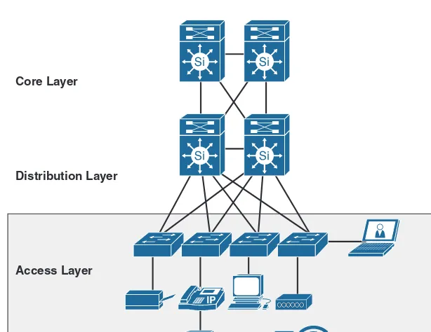
Access Layer
The access layer is the first layer, or edge, of the campus network. As shown in Figure 1-2, it’s the place where endpoints (PCs, printers, cameras, and so on) attach to the wired or wireless portion of the campus network. It is also the place where devices that extend the network out one more level are attached. Such devices include IP phones and wireless access points (APs), which are the two prime examples of devices that extend the con-nectivity out one more layer from the actual campus access switch. In addition, the access layer is the first layer of defense in the network security architecture and the first point of negotiation between end devices and the network infrastructure.
Distribution Layer Core Layer
Access Layer
Figure 1-2 Enterprise Campus: Access Layer
Table 1-1 lists examples of the various typical services and capabilities that access layer switches are required to support.3
Table 1-1 Typical Access Layer Switches Capabilities and Services
Service Requirements Service Features
Discovery and Configuration Services 802.1AF, CDP, LLDP
Security Services and Network Identity and Access
IBNS (802.1X), port security, DHCP snooping, DAI, IPSG, 802.1X, Web-Auth
Application Recognition Services QoS marking, policing, queuing, deep packet inspection NBAR, and so on
Intelligent Network Control Services PVST+, Rapid PVST+, EIGRP, OSPF, DTP, PAgP/LACP, UDLD, FlexLink, Portfast, UplinkFast, BackboneFast, LoopGuard, BPDUGuard, Port Security, RootGuard
Physical Infrastructure Services Power over Ethernet (PoE)
Distribution Layer
The distribution layer in the campus design has a unique role in that it acts as a services and control boundary between the access and the core. Both the access and the core are essentially dedicated special-purpose layers. The access layer is dedicated to meeting the functions of end-device connectivity, and the core layer is dedicated to providing non-stop connectivity across the entire campus network.4 In contrast, the distribution layer
(see Figure 1-3) serves multiple purposes, such as the following:
■ Acting as an aggregation point for all the access nodes (performing both physical link aggregations and traffic aggregation toward the core layer)
■ Providing connectivity and policy services for traffic flows within a single access-distribution block for traffic between access nodes (east-west traffic flows)
■ Providing the aggregation, policy control, and isolation demarcation point between the campus distribution building block and the rest of the network (north-south traffic flows)
Distribution Layer Core Layer
Access Layer
Links and Bandwidth Aggregation
Figure 1-3 Enterprise Campus: Distribution Layer
Therefore, the configuration choices for features in the distribution layer are often deter-mined by the requirements of the access layer (for example, are the access layer nodes intended to provide typical user access switches, or are the access layer nodes intended to be WAN routers?). Configuration choices for features in the distribution layer are also determined by the requirements of the core layer or by the need to act as an interface to both the access layer and the core layer.
Later in this chapter, the different design considerations of the distribution layer are cov-ered in more detail from different angles, such as Layer 2 and Layer 3 demarcation point placement and high-availability considerations.
Core Layer
The campus core is in some ways the simplest yet most critical part of the campus net-work. It provides a limited set of services and must be designed to be highly available and operate in an always-on mode. In today’s modern businesses, the core of the network must operate as a nonstop 7 × 24 × 365 service. The key design objectives for the campus core are based on providing the appropriate level of redundancy to allow for near- immediate data-flow recovery in the event of any component (switch, supervisor, line card, or fiber) failure. The core of the network should not implement any complex policy services, nor should it have any directly attached endpoint connections.5
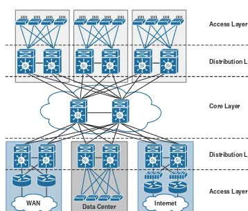
The core layer offers flexibility to the design of large campus networks to meet physical cabling and geographic challenges. For instance, consider a core layer in a campus net-work with multiple buildings (distribution blocks) like the one shown in Figure 1-4.
WAN
Distribution Layer
Distribution Layer Core Layer Access Layer
Access Layer
Layer 3 Link Layer 2 Link Internet
Data Center
Figure 1-4 Large Campus Network with a Core Layer
This design offers a solution that is scalable and flexible enough to introduce new build-ings to the network, each with its own distribution layer, without adding any complexity to network cabling or routing. As result, there is no impact on the distribution layers of the existing buildings. Nonetheless, some smaller network campus sites consisting of a single building with a smaller number of users (such as 300 users) do not require a sepa-rate core layer (assuming there is no future plan for this network to grow significantly in size, such as merging with another company).
Enterprise Campus Two-Tier Layer Model
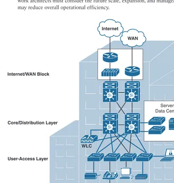
As discussed previously, smaller campus networks, such as a small remote campus loca-tion, may have several departments working on various floors within a building. In these environments, network designers can consider collapsing the core function into the distri-bution layer switch for such a small campus where there may be only a single distridistri-bution block without compromising basic network design principles, as shown in Figure 1-5. However, prior to deploying the two-tier “collapsed” core and distribution layers, net-work architects must consider the future scale, expansion, and manageability factors that may reduce overall operational efficiency.
Internet/WAN Block
Core/Distribution Layer
User-Access Layer
Layer 3 Link Layer 2 Link WLC
Server Farm/ Data Center Block Internet
WAN
This design model offers a cost-effective solution (fewer tiers means fewer devices— specifically, core devices) without sacrificing most of the benefits of the three-tier hierarchical model for small campus networks.
As shown in Figure 1-5, the distribution layer provides connectivity to network-based services, such as WAN edge devices, and to the Internet edge. These network-based services can include and are not limited to Wide Area Application Services (WAAS) and wireless LAN controllers. Depending on the size of the LAN and nature of the network (such as retail, manufacturing, or financial services), these services and their connectivity to the WAN and Internet edge might be terminated at the distribution layer switch that also provides LAN aggregation to the users’ access-layer connectivity.
With this design model, the distribution layer and core layer functions will be combined in a single layer/device, so the collapsed core/distribution device should offer the follow-ing functions and capabilities:
■ High-capacity interconnections
■ Layer 2 aggregation and a demarcation point between Layer 2 and Layer 3
■ Defined routing and network access policies
■ Intelligent network services such as QoS and network virtualization
Enterprise Campus Three-Tier Layer Model
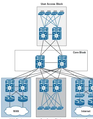
Designing large enterprise campus networks requires a dedicated distribution layer for each building (distribution block). The main campus network is typically constructed of multiple buildings. Therefore, implementing the three-tier layer model is a highly recommended and feasible design model, especially if the network is expected to grow significantly over time.
Furthermore, in large-scale enterprise campus networks, when the density of WAN routers, WAAS controllers, Internet edge devices, and wireless LAN controllers grows, it is not feasible and not advised to connect these nodes to a single distribution layer switch. This way, you avoid design and operational complexities as well as a single point of failure, which will make it an inflexible, nonresilient, and nonscalable design.
Without a Core With a Core
Figure 1-6 Enterprise Core Block (Layer)
Modularity
The modules of the system are the building blocks that are assembled into the larger campus. The advantage of the modular approach is largely due to the isolation that it can provide. Failures that occur within a module can be isolated from the remainder of the network, providing for both simpler problem detection and higher overall system availability. Also, considering modularity in your design will provide an optimized opera-tion, as network changes, upgrades, or the introduction of new services can be made in a controlled and staged fashion, allowing greater flexibility in the maintenance and less complex operation of the campus network.
In addition, a modular design offers repeatable design standards; for instance, when a specific module no longer has sufficient capacity or is missing a new function or service, it can be updated or replaced by another module that has the same structural role in the overall hierarchical design without impacting other modules in the network due to the fact that the building blocks of modular networks are easy to replicate, redesign, and expand. There should be no need to redesign the whole network each time a module is added or removed. Therefore, introducing modularity to the enterprise campus design makes the network easy to scale, understand, and troubleshoot by promoting determinis-tic traffic patterns.
Modular Enterprise Campus Architecture and Modular
Enterprise Campus with OSPF
Core Block User Access Block
WAN
WAN Block Data Center Block
Layer 3 Link Layer 2 Link
Internet/Extranet Block Internet
Figure 1-7 Modular Enterprise Campus Architecture
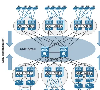
Furthermore, introducing modularity into large campus networks with multiple distribu-tion blocks will promote more optimized routing design so that you can have better fault isolation per block/module and more efficient route summarization (assuming there is a structured IP addressing scheme in which each block has its own IP range). For instance, Figure 1-8 illustrates a modular multi-area Open Shortest Path First (OSPF) routing design of a large enterprise campus network that consists of multiple blocks. The modu-lar campus architecture here will facilitate building such a structured routing design.
Note Subsequent chapters analyze and discuss routing designs in more detail.
Route Summarization
Route Summarization
WAN Data Center
Layer 3 Link Layer 2 Link Internet
OSPF Area 1 OSPF Area 2 OSPF Area 3
OSPF Area 4 OSPF Area 5 OSPF Area 6
OSPF Area 0
Access-Distribution Block
The access-distribution block of the modular enterprise campus architecture (also referred to as the distribution block) is probably one of the most familiar element of the campus architecture to network engineers. It is a fundamental component of the campus design. Properly designing the distribution block goes a long way toward ensuring the success and stability of the overall campus architecture. The access-distribution block consists of two of the three hierarchical tiers within the multilayer campus architecture: the access and distribution layers.
There are three common and proven design choices for configuring the access- distribution block and the associated control plane protocols (routing, Spanning-Tree, and so on): multitier, virtual switch (switch clustering), and routed access. Even though these designs relatively use the same basic physical topology and cabling structure, some key differ-ences exist between each design option (you must be aware of these differdiffer-ences to be able to design an optimal campus network architecture), such as where the Layer 2 and Layer 3 boundaries exist, how the network topology redundancy is implemented, and how traffic distribution works. Following are descriptions of each:
■ Multitier: This design model is primarily based on the traditional Layer 2 designs that rely on the Spanning-Tree Protocol (STP) to prevent Layer 2 loops and control traffic-forwarding topology from a Layer 2 perspective (for which the link is active). In general, this design option provides the least flexibility and fewest convergence capabilities compared to the other options. Typically, there are different topolo-gies in this design, such as the looped and loop free. Considering any one of these options can influence the level of design flexibility and convergence time. Therefore, the actual level of flexibility and fast convergence capability depends on the topol-ogy used. The subsequent section in this chapter discusses the different topologies and considerations of a resilient Layer 2 design in more detail.
Physical Layout
Layer 3
mLag
Layer 2
Logical Layout
Layer 3
Layer 2 Single IP
Gateway
Data VLAN 20 Voice VLAN 120
Figure 1-9 Virtual Switch Model
In addition, considering this design approach across all the campus blocks (when possible) will provide an optimized architecture that is easy to manage, resilient, and more flexible with higher aggregated uplink bandwidth capacity. Figure 1-10 shows how the end-to-end campus will look when the Cisco virtual switching system (VSS) is used across the different blocks and layers.
WAN Internet
Data Center WAN Data Center Internet
Physical Layout Logical Layout
Figure 1-10 Apply the Virtual Switch Model Across the Campus Blocks
model, in which the access switch acts as a full Layer 3 routed node (providing both Layer 2 and Layer 3 switching), and the access-to-distribution Layer 2 uplink trunks are replaced with Layer 3 point-to-point routed links. Consequently, the Layer 2/3 demarcation point is moved from the distribution switch to the access switch, as illustrated in Figure 1-11. The routed access-distribution block design has a number of advantages over the multitier design with its use of Layer 2 access to distribution uplinks. It offers common end-to-end troubleshooting tools (such as ping and traceroute), it uses a single control protocol (either Enhanced Interior Gateway Routing Protocol [EIGRP] or Open Shortest Path First [OSPF]), and it removes the need for features such as Hot Standby Router Protocol (HSRP). While it is the appropriate design for many environments, it is not suitable for all environments because it does not natively support spanning VLANs across mul-tiple access switches; also it can sometimes be an expensive option because the access layer switches with Layer 3 routing capability cost more than Layer 2–only switches.
Classical—STP Based
Layer 3
Layer 2
Layer 3
Layer 2 Routed Access
Figure 1-11 Routed Access Model
Flexibility
The rapidly evolving requirements of today’s modern business, such as the convergence of different communications networks such as voice, video, data, and mobility (bring your own devices, or BYOD), require a flexible enterprise campus network design that is capable of facilitating the addition and integration of these requirements and can support business growth in seamless manner. The design principle flexibility refers to the capa-bility to modify portions of the network, add new services, or increase capacity without going through a major fork-lift (major) upgrade.6
As a network designer, you need to consider a number of key areas when designing a modern enterprise campus network that can evolve over the next few years. Existing designs should be adapted to incorporate the appropriate level of flexibility to accommo-date these potential changes. Key areas to consider include the following:7
■ Control plane flexibility: The capability to support and allow migration between multiple routing, spanning-tree, and other control protocols.
■ Forwarding plane flexibility: The capability to support the introduction and use of IPv6 as a parallel requirement alongside IPv4.
■ User group flexibility: The capability to virtualize the network-forwarding capa-bilities and services in the campus fabric to support changes in the administrative structure of the enterprise. This can involve acquisition, partnering, or outsourcing of business functions.
■ Traffic management and control flexibility: Unified communications, collaborative business approaches, and software models continue to evolve—along with a trend toward increased growth in peer-to-peer traffic flows. These fundamental changes require campus designs that allow the deployment of security, monitoring, and trou-bleshooting tools available to support these new traffic patterns.
■ Flexibility to support multitenancy and traffic isolation requirements: The capa-bility to support these requirements is necessary in today’s modern networks (the following section covers this point in more detail).
Campus Network Virtualization
If we look back to the 1990s, campus LANs were characterized mainly by broad deploy-ments of Layer 2 switches. In the past two decades since the introduction of Ethernet switching, campus LAN design has significantly changed and evolved to accommo-date requirements changes. In today’s enterprise network, the growth of campus LANs drives the need to partition the network more effectively by users, location, or function. Everyone needs to retain privacy while sharing the same physical network. For end users on the network, the experience should be that of using totally separate physical networks that can be securely interconnected.8
In today’s campus networks, it is vital to provide a great degree of flexibility to accom-modate various connectivity options while keeping closed user groups (groups of users and resources isolated from nongroup members). Conceding network virtualization offers the flexibility to the design to provision different logical networks and translates to different access groups over a single physical network while keeping them logically separated; this is a solution that has challenged network operators.
One of the network virtualization approaches aims to enable a single physical entity to act in multiple physical instances in which it can be used by different user groups.
■ Access control: Also referred to as edge control, which helps ensure that legitimate users and devices are recognized, classified, and authorized to enter their assigned portions of the network. One such technology that can be used here is IEEE 802.1X, which is the standard for port authentication (refer to Chapter 25, “Designing Network Access Control Solutions,” for more details).
■ Path isolation: Helps ensure that the substantiated user or device is effectively mapped to the correct secure set of available resources, such as the relevant tenant network (virtual network) in a multitenant environment.
■ Services edge: Also referred to as services virtualization, which helps ensure that the right services are accessible to the legitimate set or sets of users and devices (for example, a multitenant data center).
Edge Control
Branch—Campus
Path Separation
End-to-End Network Virtualization Core: WAN—MAN—Campus
Services Virtualization
Data Center—Internet—Campus
Internet VRF-Lite Overlay +
VRF-Lite MPLS
Figure 1-12 Campus Network Virtualization Functional Architecture
Campus Network Virtualization Technologies and Techniques
This section discusses the foundational technology requirements to achieve network vir-tualization in a campus network and the different techniques that can be used to achieve end-to-end path isolation across the network per virtual network (VN).
VLAN Assignment
Radius Server and access switch, the switchport is dynamically changed to the appropri-ate VLAN and, optionally, an ACL can be pushed down to the switch, enforcing specific access to the network.
Virtual Routing and Forwarding
As you know from the previous section, the VLANs are the most basic path isolation technique for Layer 2, typically at the access or entry level of the user or endpoint. However, as the goal of every solid network design is to minimize the extent of the broadcast domain and exposure to spanning-tree loops, a method to translate the Layer 2 VLAN to a Layer 3 virtual network or virtual private network (VPN) is required. This Layer 3 VN must be capable of supporting its own unique control plane, complete with its own addressing structure and routing tables for data forwarding completely isolated from any other Layer 3 VPN on that device and in the network. The technology enabling this type of functionality is known as the virtual routing and forwarding (VRF) instance. Figure 1-13 illustrates how the Layer 2 VLAN mapping to the corresponding VRF at Layer 3 offers an integrated solution where you can allocate a virtual network (VN) per user group or any logical group. Moreover, based on the campus design model (multitier versus routed access) used, the VRFs are defined where the Layer 2 VLANs border the Layer 3 network. Therefore, if the access layer is connected to aggregation via Layer 2, the VRFs are defined on the distribution or collapsed core switches aggregating the access layer. If, however, the access layer is connected to Layer 3 (the routed access model), the VRFs are defined on the access switch itself.
VRF Routing Table
Distribution Switch Layer 2 < > Layer 3 Device Virtualization Access Switch
Layer 2 Device Virtualization
802.1Q Trunk VLAN X
VLAN Y VLAN Z
VRF X VRF Y VRF Z
VRF Z VRF Y
VRF X
Figure 1-13 Device Virtualization and VLAN-to-VRF Mapping