SEMANTIC LABELLING OF ROAD FURNITURE IN MOBILE LASER SCANNING
DATA
F. Li a, *, S. Oude Elberink a, G. Vosselman a
a Faculty of Geo-Information Science and Earth Observation, University of Twente, Netherlands - (f.li, s.j.oudeelberink,
george.vosselman)@utwente.nl
Commission II, WG II/3
KEY WORDS: Road Furniture Interpretation, Street Lights, Traffic Lights, Traffic Functional Signs, Mobile Laser Scanning, Point Cloud
ABSTRACT:
Road furniture semantic labelling is vital for large scale mapping and autonomous driving systems. Much research has been investigated on road furniture interpretation in both 2D images and 3D point clouds. Precise interpretation of road furniture in mobile laser scanning data still remains unexplored. In this paper, a novel method is proposed to interpret road furniture based on their logical relations and functionalities. Our work represents the most detailed interpretation of road furniture in mobile laser scanning data. 93.3% of poles are correctly extracted and all of them are correctly recognised. 94.3% of street light heads are detected and 76.9% of them are correctly identified. Despite errors arising from the recognition of other components, our framework provides a promising solution to automatically map road furniture at a detailed level in urban environments.
1. INTRODUCTION
Road furniture interpretation has received much attention in recent years, which is significant for both road safety and large scale mapping. Road furniture are entities such as traffic signs and traffic lights mounted on the road. The distribution of traffic lights and street lights has a compelling effect on the road safety. For instance, in Europe and USA, departments of transportation have established protocols to regulate road infrastructure inventory to reduce traffic accidents. Road furniture, as an essential part of the road environment, plays an important role in large scale mapping which can provide aided services in autonomous driving systems especially in bad weather conditions. Although there is a lot of attention paid to road furniture semantic labelling, they still interpret road furniture at an object level without further detailed information. Interpretation of road furniture in 2D images has been investigated. However, these 2D labelled road furniture components are not precise enough to generate 3D mapping of road furniture by dense matching. Current work on mapping road infrastructure relies on visual interpretation and manual labelling, which is tedious and time-consuming. Therefore, fully automatic road furniture interpretation is in urgent demand.
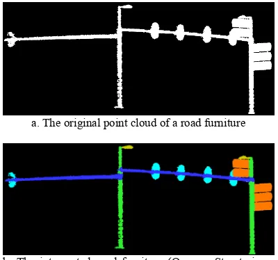
Much research has been carried out on road furniture recognition in point clouds. However, there is little attention on interpreting road furniture at a functional component level, namely semantically labelling of road furniture based on their functionalities. In this paper, we propose a method to semantically label road furniture based on their topological relations and features. One example of interpretation of road furniture by using our algorithm is as indicated as Fig. 1. The proposed method provides promising results for roadside furniture
* Corresponding author
inventory and large scale mapping. It can be potentially used for road furniture modelling.
This paper is organised as follows. The related work is reported in Section 2. Section 3 describes the methodology in detail, which involves features notation, formulation and semantics labelling. The experimental result and analysis are given in Section 4. The conclusions are drawn and future work is pictured in Section 5.
a. The original point cloud of a road furniture
b. The interpreted road furniture (Orange: Street signs, Yellow: Street lights, Cyan: Traffic lights, Green: vertical poles, Blue: Horizontal poles)
2. RELATED WORK
Model-driven methods represent an early attempt to recognize objects alongside roads from Mobile Laser Scanning (MLS) data. Several techniques used for recognition of structures in point clouds have been reviewed by Vosselman et al. (2004), which involves smooth surfaces, planar surfaces and parameterized shapes. These segmentation techniques have been widely used to model industrial installations, city landscapes, digital elevation models and trees. Brenner et al. (2009) use a local scatter matrix and a 3D cylinder stack to detect pole-like objects from MLS data. The basic principle of pole-detection is to analyse the distribution of points in both inner and outer region of cylinder. A voxel-based algorithm is proposed by Cabo et al. (2014) to detect pole-like street furniture objects from MLS data by using the similar cylinder model mask. Lehtomäki et al. (2010) develop a framework to detect vertical-pole objects by using scan line segmentation method. A classification workflow proposed by Bremer et al. (2013) uses two radius neighbourhoods to extract linear, planar and volumetric features. Rules are defined to classify objects into three categories. A percentile-based method is proposed by Pu et al. (2011) to identify pole-like structures from MLS data for road inventory studies. Li and Oude Elberink (2013) optimize the method of Pu et al. (2011) by additionally using the reflectance information. Because of reflectance information, street sign detection rate is largely improved. However, for both methods, connected road furniture, like Fig. 1, cannot be detected and recognised in this method. Another framework is proposed by El-Halawany et al. (2013) to identify road poles from mobile terrestrial laser scanning data. 2D point density is the main feature used in this method. Oude Elberink and Kemboi (2014) detect objects by using the slicing features in mobile laser scanning data. Nurunnabi et al. (2016) present a robust diagnostic PCA approach to segment laser scanning data into different parts based on local normal and curvature. In order to avoid over or under segmentation, Yang et al. (2015) introduce a super-voxel based method to classify urban objects from MLS data. Similar to Pu et al. (2011), shape information is employed by Riveiro et al. (2016) to recognize traffic signs. However, there are poles connected to many components, which makes it difficult for the method to conduct the detection.
Machine learning based methods have been widely studied by many scholars in recent years. Golovinskiy et al. (2009) propose a shape-based approach to recognize 3D point clouds in urban environments by using min-cut algorithm. Yu et al. (2015) present a method to extract street light poles from MLS point-clouds using normalized cut algorithm. Munoz et al. (2009) adopt Max-Margin Markov Networks (M3N) to classify urban scene into five categories. Ross et al. (2011) utilize message-passing algorithms to learn and predict the labels of point clouds. Based on their work, Xiong et al. (2011) propose a sequenced predictor to do 3-D scene analysis. However, the precision of pole and tree trunk recognition using M3N is low compared with the identification of other categorises. Velizhev et al. (2012) present an implicit shape models (ISM) based method to automatically localize and recognize cars and light poles. The spin image (SI) descriptor is employed as the feature representation for recognition. Yokoyama et al. (2013) propose a method
to detect and classify pole-like road furniture from MLS data. Both shape features of pole-like objects and their surrounding pole-like objects distributions are used in this method. (Yang et al., 2013; Huang and You, 2015; Soilán et al., 2016; Lehtomäki et al., 2016) employ SVM in combination with defined features to classify point clouds of urban scene by using SVM. Random forest is adopted with manually drafted features to identify objects from MLS data by (Fukano et al., 2015; Hackel et al., 2016). Weinmann et al. (2015) propose an optimal-feature-based method to classify urban environment objects into different categories by using random forest. Tombari et al. (2014) combine local descriptors and global descriptors to automatically recognize pole-like road infrastructures. Supported vector machine (SVM) and Markov random fields (MRF) are adopted at a local level and global level respectively. Song and Xiao (2014) train features generated from rendered views and make predictions to detect 3D objects by using SVM.
Deep learning as an emerging technique has been applied to object recognition in point clouds. A 3D ShapeNets is developed by Wu et al. (2015) by using Convolutional Deep Belief Network to differentiate objects in point clouds. Compared with other methods, handcrafted features are not needed. A Bag of Words (BoW) and Deep Boltzmann Machine (DBM) method is applied to detect and recognize traffic signs in mobile laser scanning (MLS) data by Yu et al. (2016). However, this method cannot undertake the semantic labelling of complex connected street furniture. A 3D convolutional neural network (ConvNets) is introduced to detect objects in RGB-D images by Song and Xiao (2016). 3D Region Proposal Network (RPN) and Object Recognition Network (ORN) are firstly proposed in their work to learn objectness from geometric shapes and extract geometric features in 3D and colour features in 2D.
Much effort has been put on road furniture recognition in point clouds. Compared with these research, the interpretation of road furniture in this paper is more detailed. In our research, we focus on the interpretation of pole-like street furniture, which consists of street lights, traffic lights and three types of traffic related signs.
3. METHODOLOGY
In this research, a method is proposed to assign meaningful labels to decomposed road furniture. Decomposed road furniture is obtained by extracting poles and separating components attached to poles, which is explained in our previous work in detail. The methodology is described in three sections. In the first section (Section 3.1), we introduce features for distinguishing different types of road furniture components. Section 3.2 describes the formulation of generic rules for the recognition of road furniture components. The process of road furniture semantic labelling is explained in the last section (Section 3.3).
3.1. Features notation
to poles. The explanation of employed features are depicted as follows.
Relative position. The relative position between poles and their corresponding attachments is summarised as bottom, middle and top. It describes the topological relations between poles and their attachments. We clarify that attachments are the components which are connected with poles. The calculation of this features is based on the percentage of attachment which is above the highest point of attached poles or underneath the lowest point of attached poles. If the percentile of attachment which is above the highest position of pole is higher than a predefined threshold, the attachment will be defined to be at the top of this pole. If the lowest position of this attachment is close to or lower than the lowest position of this pole, this attachment will be defined to be at the bottom of this pole. The relative position is set to be middle otherwise. The feature is designed to exclude attachments at the bottom of the pole such as ground points.
Relative height. This feature is the relative height between attachments and their attached poles. The relative height is the lowest height of an attachment subtract the lowest height of its attached pole. This feature is reliable because the lowest height of an attachment can reflect the usage of this attachment. It is the main constraint for street light head connected to a vertical pole.
Geometric structure. This feature indicates the geometric dimensionality of attachments, which are linear, planar and scattered. We use the definition of geometric features described by Vosselman et al. (2013).
1 scattered structure of attachments respectively;
1,
2,3
R (
1
2
3) are the three eigenvalues that correspond to an orthogonal system of eigenvectors of the covariance matrix of the points of an attachment. These three eigenvalues are calculated for every attachment, PGis the geometric structure of an attachment.
This feature is used to describe the geometric shape of attachments. It is helpful to recognize planar components such as traffic signs.
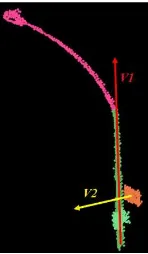
Relative angle. It is the angle between the normal of attachments and the principal direction of their corresponding connected poles. As depicted in Fig. 2, V1 is the main direction of the pole and V2 is the direction of the normal of the attachment. This is mainly used for distinguishing attached signs from other components.
Ratio of high reflectance. This simple feature is obtained by calculating ratio of high reflective points of every component. If the reflectance of an individual point is higher than a threshold, this point will be set as a point
with high reflectivity. Then the ratio of high reflective points in one component can be computed. For the reason that traffic functional signs have high reflectance, the feature is adopted to distinguish traffic functional signs and other signs.
Figure 2. The relative angle between the principal direction of a pole and the normal of an attachment
Size. This feature is designed for planar attachments. Size is the area of an attachment’s concave shape after it being projected to its normal direction. This feature is used to distinguish different types of traffic functional signs.
Ratio of height to length. The ratio of height to length gives the proportion between the height of attachments and the largest variation in the horizontal plane. This feature is utilized to differentiate street signs and other signs.
3.2. Formulation of rules and features
In this paper, we categorise street furniture attached components into 5 classes, street lights, traffic signs, street signs (direction signs), traffic information signs and traffic lights. Instances of these components are as indicated in Table 1.
Table 1. Examples of attached components
Street light Traffic sign Street sign (direction sign)
Traffic
information sign Traffic light
is decided by their minimum distance. If it is smaller than a threshold, it is considered to be connected.
The following rules are defined to assign a semantic label to each component of road furniture. We first start with rules for components connected to a vertical pole.
Street lights connected to a vertical pole (R1): If there is a component connected to a vertical pole, its relative height is larger than a threshold Hsl and it is on the top of this pole, this component will be street light. Hsl is the threshold of discriminant feature to recognize street light head.
Traffic signs connected to a vertical pole (R2): If there is a component connected to a vertical pole, it is not at the bottom of this pole, its relative angle is perpendicular, it is linear or planar, its area is smaller than Ats, its ratio (height to length) is close to 1 and its ratio of high reflectance points is larger than Rts, this component will be a traffic sign. Ats is important for differentiating traffic signs from other traffic functional signs.
Street signs / direction signs connected to a vertical pole (R3): Conditions are the same as traffic signs except that the area is smaller than Ass and size ratio is smaller than Rss. Then this component should be a street sign or direction sign. The ratio of size is significant for distinguishing street signs from other traffic functional signs.
Traffic information signs connected to a vertical pole (R4): Traffic information signs are usually large. Conditions are the same as street signs except that the area is larger than max (Ats, Ass) and there is no constraint of size ratio. Then this component should be a traffic information sign.
Traffic lights connected to a vertical pole (R5): If there is a component connected to a vertical pole, it is not planar and its relative height is smaller than Hsl, this component should be a traffic light.
Then these are rules for components connected to a horizontal pole.
Street signs / direction signs connected to a horizontal pole (R6): If there is a component connected to a horizontal pole, its relative angle is perpendicular, it is linear or planar, its area is smaller than Ats, its ratio (height to length) is smaller than Rss and its ratio of high reflectance points is larger than Rts, this component will be a traffic sign.
Traffic information signs connected to a horizontal pole (R7): Conditions are the same as street signs except that the area is larger than max (Ats, Ass) and there is no constraint of size ratio. Then this component should be a traffic information sign.
Traffic lights connected to a horizontal pole (R8): If there is a component connected to a horizontal pole, it is not planar, this component should be a traffic light.
3.3. Semantics labelling
Based on these rules, labels are assigned to the attachments. Poles are first detected by our previous work. Specifically, based on their principal direction, poles are recognised to be vertical and horizontal. Then the connectivity between attached components and poles is analysed. Based the connectivity relations, attachments are found for every pole. Features mentioned above are produced for every attachment afterwards. Then these attachments are given labels by fitting predefined rules with these generated features. Before giving labels to the attachments, the parameters are optimized by selecting the best combination of parameters in the training area. An example of complex road furniture interpretation is as shown in Fig. 1.
4. EXPERIMENTAL RESULT
The experimental test is carried out in two datasets, which are described in Section 4.1. The result and analysis are explained in the following Section 4.2 and Section 4.3.
4.1. Test sites
In order to evaluate the performance of this innovative method, we chose two test areas. Dataset A is collected in a medium size city located in Europe. Data acquisition system is Optech LYNX which comprises two laser scanner mounted at the back of a moving vehicle. Dataset B is Paris benchmark dataset, collected by Stereopolis II system (IGN, 2013). There are many different types of road furniture in these two research areas. Dataset A covers about 1.25km of street scene, and Dataset B covers approximate 0.43km of road scene. The point density of dataset A is high and even. The distance between neighbouring points is 0.02m in X direction and 0.03m in Y direction. In contrast, the point density in dataset B is low and uneven. The point density along the scanline direction is much higher than the point density perpendicular to the scanline direction.
4.2. Results
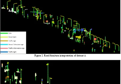
Figure 2. Road furniture interpretation of dataset A
Figure 3. Road furniture interpretation in dataset B
The result of road furniture interpretation in dataset A is shown in Fig. 2. The interpretation of road furniture in dataset B is as illustrated in Fig. 3. White components represents unrecognised components or uninteresting components such as ground points and non-traffic functional attachments.
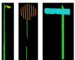
From the result, we can see road furniture are interpreted correctly. Individual examples of correctly interpreted road furniture in Dataset A are as indicated in Fig. 4. Poles (green points), street lights (yellow), traffic signs (orange), street signs (cyan) and traffic lights (blue) are correctly recognised. These road furniture are interpreted correctly in a detailed level based on their functionalities. Fig. 5 shows some correct results of road furniture interpretation in Dataset B.
Figure 5. Correct interpretation of road furniture in Dataset B
4.3. Analysis
In the assessment, a confusion matrix is used to evaluate the performance of our proposed framework (Table 2 and Table 3). The recognition of six types of road furniture is evaluated. In these tables, P stands for poles, S1 represents street lights, S2 stands for street signs, T1 symbolises traffic signs, T2 stands for traffic information sign and T3 represents traffic lights. M is for the road furniture components that are not given any labels. T is the total number of visually interpreted components. R is the recognition rate of this algorithm. Other are other components which are misrecognised as road furniture components. Total is the number of road furniture components which are recognised by the algorithm. FP is the false positive rate.
Table 2. The evaluation of road furniture interpretation in Dataset A
Visual interpretation FP (%) P S1 S2 T1 T2 T3 Other Total
P 111 0 0 0 0 0 0 111 0
S1 1 50 0 3 5 1 5 65 23.1
S2 0 0 7 5 0 0 0 12 41.7
T1 0 1 5 27 1 1 1 36 25.0
T2 0 0 1 0 3 0 0 4 25.0
T3 0 0 0 4 0 16 1 21 23.8
M 7 2 4 14 2 13
T 119 53 17 53 11 31
R (%) 93.3 94.3 41.2 50.9 27.3 51.6
Table 3. The evaluation of Paris road furniture interpretation in Dataset B
Visual interpretation FP (%) P S1 S2 T1 T2 T3 Other Total
P 33 0 0 0 0 0 0 33 0
S1 0 7 0 0 0 4 0 11 36.4
S2 0 0 1 2 0 0 0 3 66.7
T1 0 0 0 7 2 3 0 12 41.7
T2 0 0 0 0 0 0 0 0 0
T3 0 0 0 0 0 9 0 9 0
M 9 0 3 4 0 28
T 42 9 4 13 2 44
R (%) 78.6 77.8 25.0 53.8 0 20.4
In dataset A, 93.3% of poles are extracted by using decomposition which can be found in our previous work. All the detected poles are true positives. One horizontal pole is recognised as street light because this horizontal
pole is not extracted as a pole at the decomposition stage. In addition, its relative height and relative position is similar to street lights, which gives rise to misrecognition. 94.3% of street light heads are detected and 50 out of 65 detected street light heads are correct. 50.9% of traffic signs are recognised, 27 out of 36 detected traffic signs are correct. Many of them are missed because their geometric structure and reflectance attributes are not calculated reliably. Through training, the threshold of reflectance is set to be 65. However, in view of that traffic signs can only be scanned one side when their normal is perpendicular to the driving direction, a few traffic signs do not have high reflectance. Another reason is their geometric structure is scattered result from small sized traffic signs being more effected by noisy points. As shown in Fig. 6, the point cloud of the traffic sign (in red circle) is scattered because of noisy points, which incurs it being misrecognised as street light. 41.2% of street signs are extracted and 7 out of detected 12 are correct. 27.3% of traffic information signs are recognised and 3 of detected 4 are correct. The recognition rate of traffic light is 51.6%. 16 out of 21 detected traffic lights are correct. The recognition rate of street sign and traffic information sign is lower than 50.0% and the identification rate of traffic sign is 50.9%. One reason is that there are few instances of street signs and traffic information signs. An error in a small dataset has a larger influence on the percentage of recognition. Another reason is that the computation of geometric structure, size and reflectance of street signs and traffic signs is not correct in view of that the point cloud collection of these small sized sign components is incomplete. The recognition rate of traffic lights is not high because there are many traffic lights scanned incompletely, which leads to their incorrect structure features. Most of them are categorized as signs because of their high planarity. Later on more effort will be investigated to distinguish them.
Figure 6. The point cloud of traffic sign (the left) and street view (the right)
high planarity. Using geometric structure is not sufficient to recognize traffic lights in Dataset B.
Figure 7. One road furniture which contains an unrecognised traffic light (white points) in Dataset B
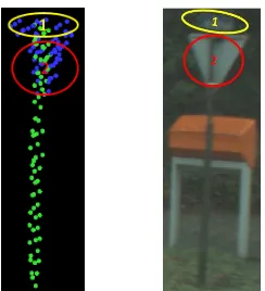
From the result, we conclude that poles can be extracted well. Street lights can be recognised reliably if the point cloud is dense and of good quality. Some street signs are labelled as traffic lights because these street signs are still connected with each other and not separated. The reason is the data is too noisy. As illustrated in the second image of Fig. 8, component 1 (yellow area) and component 2 (red zone) should be separated. Due to the noisy data, component 1 and component 2 are not separated by decomposition algorithm (the first image of Fig. 8), which results in the misrecognition.
Figure 8. One example of incorrectly recognized road furniture
5. CONCLUSIONS AND FUTURE WORK
To conclude, this paper provides a method to interpret road furniture at a detailed level. In dataset A, 93.3% of poles are correctly extracted and all of them are correctly recognised. 94.3% of street light heads are detected and 76.9% of them are correctly identified. Street light heads are extracted well. In contrast, other types of components are not well identified because incomplete scanned data affecting the computation of features. Another reason is the quality of data affects the recognition. For example, part of components in dataset B can even not be interpreted by visual inspection. In addition, these interpreted components are very similar, which makes it even more challenging.
Although there are errors, the result still provides a promising solution to assist large scale street furniture mapping. Future work will be investigated on using the combination of relations between components and
relations between individual road furniture to generate 3D road furniture models.
REFERENCES
Bremer, M., Wichmann, V., & Rutzinger, M., 2013. Eigenvalue and graph-based object extraction from mobile laser scanning point clouds. ISPRS Annals of Photogrammetry, Remote Sensing and Spatial Information Sciences, Vol. II-5/W2, pp. 55–60.
Brenner, C., 2009. Extraction of features from mobile laser scanning data for future driver assistance systems. Springer, Hannover. pp. 25-42.
Cabo, C., Ordoñez, C., García-Cortés, S., & Martínez, J., 2014. An algorithm for automatic detection of pole-like street furniture objects from Mobile Laser Scanner point clouds. ISPRS Journal of Photogrammetry and Remote Sensing, 87, pp. 47-56.
El-Halawany, S.I. and Lichti, D.D., 2013. Detecting road poles from mobile terrestrial laser scanning data.GIScience & Remote Sensing,50(6), pp. 704-722.
Fukano, K. and Masuda, H., 2015. Detection and Classification of Pole-Like Objects from Mobile Mapping Data. ISPRS Annals of Photogrammetry, Remote Sensing and Spatial Information Sciences, 1, pp. 57-64.
Golovinskiy, A., Kim, V. G. and Funkhouser, T., 2009. Shape-based recognition of 3D point clouds in urban environments. IEEE International Conference on Computer Vision, Kyoto, Japan, pp. 2154–2161.
Hackel, T., Wegner, J.D. and Schindler, K., 2016. Fast semantic segmentation of 3D point clouds with strongly varying density.ISPRS Annals of the Photogrammetry, Remote Sensing and Spatial Information Sciences, Vol. III-3, pp. 177-184.
Huang, J. and You, S., 2015. Pole-like object detection and classification from urban point clouds. IEEE International Conference on Robotics and Automation, Seattle, Washington USA, pp. 3032-3038.
Lehtomäki, M., Jaakkola, A., Hyyppä, J., Kukko, A. and Kaartinen, H., 2010. Detection of Vertical Pole-Like Objects in a Road Environment Using Vehicle-Based Laser Scanning Data. Remote Sensing, 2(3), pp. 641-664.
Lehtomäki, M., Jaakkola, A., Hyyppä, J., Lampinen, J., Kaartinen, H., Kukko, A., Puttonen, E. and Hyyppä, H., 2016. Object classification and recognition from mobile laser scanning point clouds in a road environment. IEEE Transactions on Geoscience and Remote Sensing, 54(2), pp. 1226-1239.
Li, D. and Oude Elberink, S., 2013. Optimizing detection of road furniture (pole-like objects) in mobile laser scanner data. ISPRS Annals of Photogrammetry, Remote Sensing and Spatial Information Sciences, Vol. II-5/W2, pp. 163-168.
Remote Sensing and Spatial Information Science
s
,
Vol. III-3, pp. 193-200.Munoz, D., Bagnell, J. A., Vandapel, N. and Hebert, M., 2009. Contextual classification with functional max-margin Markov networks. Proceedings of the IEEE Conference on Computer Vision and Pattern Recognition, pp. 975–982.
Nurunnabi, A., Belton, D. and West, G., 2016. Robust Segmentation for Large Volumes of Laser Scanning Three-Dimensional Point Cloud Data. IEEE Transactions on Geoscience and Remote Sensing, 54(8), pp.4790-4805.
Oude Elberink, S. and Kemboi, B., 2014. User-assisted object detection by segment based similarity measures in mobile laser scanner data. The International Archives of the Photogrammetry, Remote Sensing and Spatial Information Sciences, Vol. XL-3, pp. 239-246.
Pu, S., Rutzinger, M., Vosselman, G., & Oude Elberink, S., 2011. Recognizing basic structures from mobile laser scanning data for road inventory studies. ISPRS Journal of Photogrammetry and Remote Sensing, 66(6), pp. S28-S39.
Riveiro, B., Díaz-Vilariño, L., Conde-Carnero, B., Soilán, M. and Arias, P., 2016. Automatic segmentation and shape-based classification of retro-reflective traffic signs from mobile lidar data. IEEE Journal of Selected Topics in Applied Earth Observations and Remote Sensing, 9(1), pp. 295-303.
Ross, S., Munoz, D., Hebert, M. and Bagnell, J.A., 2011. Learning message-passing inference machines for structured prediction. Proceedings of the IEEE Conference on Computer Vision and Pattern Recognition, pp. 2737-2744.
Soilán, M., Riveiro, B., Martínez-Sánchez, J. and Arias, P., 2016. Traffic sign detection in MLS acquired point clouds for geometric and image-based semantic inventory.
ISPRS Journal of Photogrammetry and Remote Sensing, 114, pp. 92-101.
Song, S. and Xiao, J., 2014. Sliding shapes for 3d object detection in depth images. Proceedings of the European conference on computer vision, Vol. VI, pp. 634-651.
Song, S. and Xiao, J., 2016. Deep sliding shapes for Amodal 3D object detection in RGB-D images.
Proceedings of the IEEE Conference on Computer Vision and Pattern Recognition, pp. 808-816.
Tombari, F., Fioraio, N., Cavallari, T., Salti, S., Petrelli, A. and Di Stefano, L., 2014. Automatic detection of pole-like structures in 3d urban environments. Proceedings of the IEEE/RSJ International Conference on Intelligent Robots and Systems, pp. 4922-4929.
Velizhev, A., Shapovalov, R. and Schindler, K., 2012. Implicit shape models for object detection in 3D point clouds. ISPRS Annals of the Photogrammetry, Remote Sensing and Spatial Information Sciences, Vol. I-3, pp. 179-184.
Vosselman, G., 2013. Point cloud segmentation for urban scene classification. The International Archives of
Photogrammetry, Remote Sensing and Spatial Information Sciences, Vol. XL-7/W2, pp. 257-262.
Vosselman, G., Gorte, B. G., Sithole, G., & Rabbani, T., 2004. Recognising structure in laser scanner point clouds.
The International Archives of Photogrammetry, Remote Sensing and Spatial Information Sciences, Vol. XXXVI -8/W2, pp. 33-38.
Weinmann, M., Jutzi, B., Hinz, S. and Mallet, C., 2015. Semantic point cloud interpretation based on optimal neighborhoods, relevant features and efficient classifiers. ISPRS Journal of Photogrammetry and Remote Sensing, 105, pp. 286-304.
Wu, Z., Song, S., Khosla, A., Yu, F., Zhang, L., Tang, X. and Xiao, J., 2015. 3D ShapeNets: A deep representation for volumetric shapes. Proceedings of the IEEE Conference on Computer Vision and Pattern Recognition, pp. 1912-1920.
Xiong, X., Munoz, D., Bagnell, J. A. and Hebert, M., 2011. 3-D scene analysis via sequenced predictions over points and regions. Proceedings of the IEEE International Conference on Robotics and Automation, pp. 2609–2616.
Yang, B. and Dong, Z., 2013. A shape-based segmentation method for mobile laser scanning point clouds. ISPRS Journal of Photogrammetry and Remote Sensing, 81, pp. 19-30.
Yang, B., Dong, Z., Zhao, G. and Dai, W., 2015. Hierarchical extraction of urban objects from mobile laser scanning data. ISPRS Journal of Photogrammetry and Remote Sensing, 99, pp. 45-57.
Yang, B., Liu, Y., Liang, F. and Dong, Z., 2016. Using mobile laser scanning data for features extraction of high accuracy driving maps. The International Archives of Photogrammetry, Remote Sensing and Spatial Information Sciences, Vol. XLI-B3, pp. 433-439.
Yokoyama, H., Date, H., Kanai, S. and Takeda, H., 2013. Detection and classification of pole-like objects from mobile laser scanning data of urban environments.
International Journal of CAD/CAM, 13(2), pp. 31-40.
Yu, Y., Li, J., Guan, H., Wang, C. and Yu, J., 2015. Semiautomated extraction of street light poles from mobile LiDAR point-clouds. IEEE Transactions on Geoscience and Remote Sensing, 53(3), pp. 1374-1386.