ROI-ORIENTATED SENSOR CORRECTION BASED ON VIRTUAL STEADY
REIMAGING MODEL FOR WIDE SWATH HIGH RESOLUTION OPTICAL
SATELLITE IMAGERY
Ying Zhu a,b, Shuying Jin a, Yuan Tian a, Mi Wang a*a LIESMARS, Wuhan University, No.129 Luo Yu Road, Wuhan, China- [email protected], [email protected], [email protected], [email protected]
b School of Resource and Environmental Sciences, Wuhan University, No.129 Luo Yu Road, Wuhan, China
ISPRS ICWG III/IVb
KEY WORDS: Sensor correction, ROI, Steady reimaging, High resolution optical satellite, Wide swath imagery
ABSTRACT:
To meet the requirement of high accuracy and high speed processing for wide swath high resolution optical satellite imagery under emergency situation in both ground processing system and on-board processing system. This paper proposed a ROI-orientated sensor correction algorithm based on virtual steady reimaging model for wide swath high resolution optical satellite imagery. Firstly, the imaging time and spatial window of the ROI is determined by a dynamic search method. Then, the dynamic ROI sensor correction model based on virtual steady reimaging model is constructed. Finally, the corrected image corresponding to the ROI is generated based on the coordinates mapping relationship which is established by the dynamic sensor correction model for corrected image and rigours imaging model for original image. Two experimental results show that the image registration between panchromatic and multispectral images can be well achieved and the image distortion caused by satellite jitter can be also corrected efficiently.
1. INTRODUCTION
High resolution optical satellite, playing an important role in Earth Observation System, can obtain the imagery covering the surface of the Earth with ground sampling distance (GSD) of several meters and even less than 1 m. Worldview-3/4, launched in 2014 and 2016 respectively, have reached 0.3 m GSD. Gaofen-2, one of the optical satellites of Chinese High Resolution Observation System, also can obtain imagery with sub-meter GSD. When the spatial resolution is improved higher, the imaging rang will be smaller than before. To improve the imaging efficiency, increasing the imaging width is a direct and effective method, which can obtain a larger imaging range at one time. However, wider imaging swath leads to an exponential increase in the amount of imaging data, which not only brings pressure to data transmission, but also reduces the efficiency of data processing and application, especially for the rapid emergency response applications, such as monitoring of earthquake area, dynamic monitoring of time sensitive target. So region of interest (ROI)-oriented data processing, which can obtain data and information quickly and efficiently, is a useful strategy for emergency situation in both ground processing system and on-board processing system.
Sensor correction is currently a prerequisite step for photogrammetric processing and application of high resolution optical satellite, which mainly solves the problem caused by camera design and imaging characters, such as image distortion caused by lens distortion and unstable platform, sub-CCD image stitching and band-to-band registration for multispectral image. The standard image product with rational function model (RFM) can be obtained after sensor correction.
Many researchers have made great efforts to realize sensor correction with high accuracy and low time cost. In general, the
* Corresponding author
existing sensor correction method can be categorized into two classes: (1) image-space-oriented method, and (2) object-space-oriented method (Hu, 2010). The image-space-object-space-oriented method is based on image matching and registration, mainly solving the problem of sub-CCD image stitching and band-to-band registration (Pan, et al., 2011; Li et al., 2009; Lu,2010 ). The shift transformation model, piecewise affine transformation model, or piecewise polynomial transformation model, etc. are often established and used for image correction, based on tie points of adjacent sub-images or different bands of images extracted with image matching operators(Tang et al, 2014). The object-space-oriented method establishes the corresponding relationship between original image and corrected image based on the imaging geometric model with the object space as an intermediary, which is stricter in theory and more desirable for high-precision image processing and application. A virtual CCD for corrected image is used to replace the original sub-CCDs with multiple bands in this method (Jacobsen, 2006; Zhang et al., 2012; Pan et al., 2013). Wang et al. (2016) further proposed a virtual steady reimaging model based on the virtual CCD to correct distortion caused both camera and satellite jitter.
2. METHODOLOGY
2.1 Rigorous imaging model and virtual steady reimaging model
2.1.1 Rigorous imaging model: The rigorous imaging model, which describes the physical properties of image acquisition through the relationship between the image and the ground coordinate system, is mainly determined based on the condition of collinearity through an interior orientation model and an exterior orientation model which help convert the image coordinates to camera coordinates and satellite body coordinates to object coordinates, respectively (Poli and Toutin, 2012; Toutin, 2004).
The interior orientation elements, parameters of interior orientation model are usually described by the look angle of the LOS in camera coordinates and determined by laboratory calibration before launching and updated by inflight calibration during a certain period after launching (Wang et al., 2014; Xu et al., 2014). The exterior orientation elements, including ephemeris and attitude, are obtained from the onboard GPS receiver and attitude determination system (ADS), respectively.
For the original image, the rigorous imaging model of each line can be established as follows:
( )
where t = imaging time of the scan line recorded by the camera
λ= scale factor
ψ ψx, y = the look angles;
sensor body
R = the install matrix calculated by inflight calibration,
which can be treated as a fixed value over a long period time
( ( ), ( ), ( )) body
ECI
R ψ t ω t κt = rotation matrix from the ECI
coordinate system to the satellite body coordinate system converted by rotation angles ψ( ),t ω( ),t
andκ( )t .
( ),t
ψ ω( ),t κ( )t = pitch, roll and yaw angle, interpolated from the attitude observation under the ECI coordinate system by time
( )
ECI ECR
R t = transformation matrix from the ECF coordinate
system to the ECI coordinate system
[ ( ) ( ) ( )]T
S S S
X t Y t Z t = position vector of the projection center in the ECF coordinate system, interpolated from the ephemeris observation by time.
2.1.2 Virtual steady reimaging model: Considering distortion in the image caused by lens distortion, CCD deformation, integration time jumping etc. from camera and attitude oscillation from satellite movement, a virtual steady reimaging (VSRI) model for undistorted image was proposed by Wang et al (2016). In this model, a virtual CCD, which is a unique CCD linear array covering the whole swath without any distortion or deformation and integration time jumping, is used to replace the original sub-CCDs and the attitude angles (pitch, roll and yaw) of the virtual steady reimaging is smooth.
The VSRI model is established as follows:
( )
coordinate system to the satellite body coordinate system
( ), ( ), ( )t t t
ψ ω κ = rotation angle interpolated from the filtered attitude observation under the ECI coordinate system by time t.
λ, Rbodysensor, ( ) ECI ECR
R t , and [XS( )t Y tS( ) ZS( )t]T have the same
meaning as in the rigorous imaging model for the original image shown in equation (1).
2.2 ROI-orientated sensor correction based on steady reimaging model
The ROI-orientated sensor correction consists of three main steps: 1) determination of the imaging time and spatial window of the ROI; (2) construction of the dynamic ROI sensor correction model; 3) generation and evaluation of the sensor-corrected ROI image.
2.2.1 Determination of the imaging time and spatial window of the ROI: To conduct the ROI-orientated sensor correction, it is necessary to determine the imaging time and spatial window of the ROI, so that orientation parameters including attitude, orbit, camera parameters etc. can be further determined from the image data and its auxiliary data including imaging time data, attitude data, orbit data, camera file.
A dynamic search method is used to determine the imaging time window as shown in Figure 1 (a). Firstly, the ground coordinates of imaging lines at t1 and t2 are calculated, where t1 is the imaging time of the first scan line and t2 is determined by t1 plus an approximate time interval ∆t1 which can fully cover the imaging
period of ROI. If the ROI is in imaging area corresponding to the period of t1t2, the time window t1t2 will be further equally divided into three parts including t1t3, t3t4, and t4t2 by a smaller interval
2 t
∆ . And a more accurate time window will be further determined like before until the accurate time window t5t6 corresponding to the ROI is found. Whereas, the coordinates corresponding to the next time interval starting with t2 and ending with t2 plus the same interval with t1t2 will be calculated until the ROI is found.
(a) Imaging time window determination
(b) Imaging spatial window determination Figure 1. Schematic diagram of imaging time and spatial
window determination
2.2.2 Construction of the dynamic ROI sensor correction model: Different from the traditional image sensor correction, the ROI-orientated sensor correction is more flexible in the imaging time and imaging space. Therefore, the ROI-orientated sensor correction needs to build dynamic sensor correction model based on the imaging window.
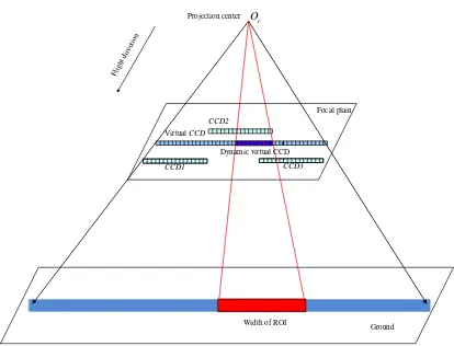
The ROI-orientated sensor correction model is essentially a rigorous imaging model. For traditional image sensor correction model, the interior orientation element model of the sensor correction model for the corrected image is statically constructed based on the virtual CCD which is a unique CCD linear array covering the whole swath without any distortion or deformation. For ROI-orientated sensor correction model, the interior orientation element model is dynamically constructed based on the virtual CCD due to the dynamic change of the ROI range named "dynamic virtual CCD". As shown in figure 2, to achieve inner orientation modelling of dynamic virtual CCD, the full-field virtual CCD covering the entire image range is determined first and dynamic virtual CCD is further determined according to the imaging space window. Then, the external orientation model is established according to the imaging time window from the filtered attitude data like the traditional image sensor correction (Wang et al., 2016). Finally, ROI-orientated sensor correction model can be constructed by the interior orientation model and exterior orientation model.
Figure 2. Schematic diagram of dynamic ROI sensor correction model
Flight direction
△t1
△t2 △t3
t1 t3 t5 t6 t4 t2
t5 t6
b c
d a Flight direction
c
O
Flight direction
Virtual CCD
CCD1 CCD3
CCD2
Width of ROI Dynamic virtual CCD
Focal plain
2.2.3 Generation and evaluation of the sensor-corrected ROI image: The corrected image corresponding to the ROI can be generated based on the coordinates mapping relationship which is established by the dynamic sensor correction model for corrected image and rigours imaging model for original image. To improve the calculation efficiency, the rational function model is used as the replacement model for the dynamic sensor correction model of the corrected image. By forward intersection, the corresponding points on the corrected image and original image will intersect on the ground. The image coordinates mapping relationship between corrected image and original image can be determined by the coordinate of ground point. Then the corrected image can be generated by image resampling.
The geometric accuracy of the ROI sensor corrected image is mainly based on the positioning accuracy. Evaluation of positioning accuracy for the corrected image needs a certain number of ground control points (GCPs) which can be obtained by GPS field measurements or measured from the reference image. What’s more, it is necessary to evaluate the band-to-band registration accuracy for multi spectral images.
The positioning accuracy is obtained by calculating the root mean squared error (RMSE) of the coordinate’s differences between the measured coordinate and back projected coordinates on the image from the ground coordinates of the GCPs. The band-to-band registration accuracy for multi spectral images is evaluated by calculating the RMSE of the coordinate’s differences of corresponding points between each two bands.
3. EXPERIMENTS AND DISCUSSION
3.1 Experimental data
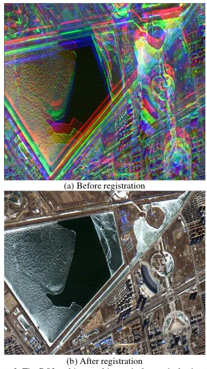
Two datasets were used to validate the proposed method. Dataset one is a ROI image with five bands including panchromatic, blue, green, red and infrared band, where the panchromatic image is with 1 m GSD and the other four multispectral images are with 4 m GSD. Before sensor correction, these five bands of images have a problem of misregistration due to the camera design, as shown in figure 3(a).
Dataset two is a ROI panchromatic image covering a calibration field, as shown in figure 4(a). Due to the satellite jitter, the edges of the square target are not straight as expected, as shown in figure 5(a).
3.2 Results and discussion
3.2.1 Results and analysis of datasets one: As shown in figure 3(a), the images of different bands are misalignedbefore the sensor correction processing. To solve this problem, the ROI-orientated sensor correction based on virtual steady reimaging model was conducted. Different bands of images have the same virtual CCD. Figure 3(b) gives the results of the corrected images. It is obvious that the multispectral image is well aligned after registration.
To quantitatively evaluate the registration accuracy, image matching based on least square algorithm is used to collect enough number of corresponding points with sub-pixel accuracy between two bands of images. Taking green band as reference, the registration accuracy of other three bands of images was assessed. To evaluate the registration accuracy between panchromatic image and multispectral image, the green band up-sampled to the same GSD with the panchromatic image. The average error (AE) and root mean square error (RMSE) of the
coordinate differences of corresponding points are calculated and listed in table 1.
(a) Before registration
(b) After registration
Figure 3. The ROI multispectral image before and after band-to-band registration
Table 1. The registration evaluation results of corrected image Band combination
/GSD
AE/pixel RMSE/pixel
x y x y
Red-Green/4m 0.036 0.011 0.108 0.120 Blue-Green/4m -0.016 -0.026 0.105 0.124
Infrared-Green/4m
-0.007 -0.001 0.122 0.111
Green-PAN/ 1m 0.017 -0.018 0.726 0.613
The results show that the registration accuracy between red -green, blue-green and infrared-green is less than 0.2 pixels in both across and along track. And the RMSE of green and panchromatic images is less than 1 pixel in panchromatic image, which fully satisfies the requirement of applications such as image fusion.
3.2.2 Results and analysis of datasets two: As shown in Figure 4(a), the edges of the square target in the level-0 image have different degrees of deformation (bending) caused by satellite jitter. The amplification effect of the target in the red border is shown in Figure 5 (a).
jitter in both directions is about 100 Hz, which means one jitter period is 0.01 s. So the distortion caused by satellite jitter is easy to be found visually.
To correct the distortion, sensor correction based on VSRI is conducted. The correction result is shown in Figure 4 (b) and 5 (b). The deformation of the corrected image has been removed obviously, which shows the reliability of the proposed method.
(a) Before correction (with deformed targets in the rectangles)
(b) After correction
Figure 4. The image with targets before and after sensor correction
(a) Before correction
(b) After correction
Figure 5. The target in the green rectangle in figure 7 before and after sensor correction (in left image, the red dashed
line is the edge of the deformed target, and the green solid line is the true shape of the target)
4. CONCLUSIONS
ACKNOWLEDGEMENTS
This work was substantially supported by the National Natural Science Foundation of China (grant numbers 41371430, 91438112, 91438203, 91438111); and the Central University Basic Scientific Research Special Funds.
REFERENCES
Fraser, C.S., Hanley, H.B., 2005. Bias-compensated RPCs for sensor orientation of high-resolution satellite imagery. Photogrammetric Engineering and Remote Sensing, 71(8) , pp. 909-915.
Hu, F., 2010. Research on Inner FOV Stitching Theories and Algorithms for Sub-Images of Three Non-collinear TDI CCD Chips. Doctoral dissertation, Wuhan University, Wuhan, China.
Jacobsen, K., 2006. Calibration of imaging satellite sensors. Int. Arch. Photogramm. Remote Sensing, 36, p. 1.
Li, S., Liu, T., Wang, H., 2009. Image mosaic for TDI CCD push-broom camera image based on image matching. Remote Sensing, 24, pp. 374-378.
Lu, J., 2010. Automatic mosaic method of large field view and multi-channel remote sensing images of TDICCD cameras. Master’s Thesis, Changchun Institute of Optics, Fine Mechanics and Physics, Chinese Academy of Sciences, Jilin, China.
Pan, H., Zhang, G., Tang, X., et al., 2013. The Geometrical Model of Sensor Corrected Products for ZY-3 Satellite. Acta Geodaetica et Cartographica Sinica, 42(4) , pp.516-522.
Pan, J., Zhu, Y., Wang, M., 2011. Parallel Band-to-band Registration for HJ-1A/1B CCD images Using OpenMP. Image and Data Fusion (ISIDF), 2011 International Symposium on IEEE, Tengchong, China (15 Aug. 2011).
Poli, D., Toutin, T., 2012. Review of developments in geometric modelling for high resolution satellite pushbroom sensors. The Photogrammetric Record, 27(137) , pp. 58-73.
Tang, X., Hu, F., Wang, M., et al, 2014. Inner FoV Stitching of Spaceborne TDI CCD Images Based on Sensor Geometry and Projection Plane in Object Space. Remote Sensing, 6(7) , pp. 6386-6406.
Toutin, T., 2004. Review article: Geometric processing of remote sensing images: models, algorithms and methods. International Journal of Remote Sensing, 25(10), pp. 1893-1924.
Zhang, G., Liu, B., Jiang, W., 2012. Inner FOV stitching algorithm of spaceborne optical sensor based on the virtual CCD line. J. Image Graphics, 17, pp.696-701.
Wang, M., Yang, B., Hu, F., Zang, X., 2014. On-orbit geometric calibration model and its applications for high-resolution optical satellite imagery. Remote Sensing, 6(5), pp. 4391-4408.
Wang M, Zhu Y, Jin S, et al., 2016. Correction of ZY-3 image distortion caused by satellite jitter via virtual steady reimaging using attitude data. ISPRS Journal of Photogrammetry and Remote Sensing, 119, pp. 108-123.