Design Aspect of including Infill Wall in RC Frame Design
*Sukrawa, M.
1Abstract: This study compares analysis and design of a four story reinforced concrete (RC) frame structure with infill wall at upper levels and open at basement level. For the analysis, the RC frame are modeled as open frame (MOF) and infilled-frames using six compression only cross diagonal strut (MIF-Strut), and infilled frame using shell elements (MIF-Shell). Another model, MIF-Full, is created by adding walls at basement level of the MIF-Strut to study the effect of wall discontinuity. All three dimensional models are loaded with gravity load and quake load appropriate for South Bali region. Results show that the infilled-frame models are 4.8 times stiffer than MOF in the wall direction. Perpendicular to the wall, however, the stiffness increase is 29%. Soft storey mechanism exists in the absence of wall at basement level, regardless of reasonable column dimensions.
Keywords: Infilled-frame, strut model, shell element, soft storey, RC frame design.
Introduction
In hotel or apartment of low rise buildings, many reinforced concrete (RC) frame structures are con-structed with walls between rooms. The walls are usually made of solid brick or concrete block to prevent noise coming from the neighboring rooms. The existence of the wall, however, is usually consi-dered nonstructural in design because the method of analysis is not simple and not yet readily available in building codes. This is surprising as investigations on the interaction between infill panel and the frame structures has begun since 1950s [1,2]. In Indonesia, there is an old code that cover infill wall in RC structures design [3]. However, the code does not reflect the state-of-knowledge of the day. There are so many restriction and conditions in the code that prevent inclusions of the wall in frame analysis and design, while many reports suggest the importance of including wall in frame analysis.
Despite the lack of design guide, many researchers already proposed analysis methods for infilled-frame using equivalent diagonal strut [1-6] and shell ele-ment [7-9]. While each method has its shortcoming, comparison with experimental test results showed that the strut model gives lateral stiffness compa-rable to the test value [7,8]. FEMA 306 [1] suggests that a single equivalent-strut approach could be successfully used for design and evaluation studies of infilled-frame systems.
*Part of this paper was presented at EACEF 2013, Singapore
1 Civil Engineering Department, University of Udayana, Bali – INDONESIA. Email: [email protected]
Note: Discussion is expected before June, 1st 2014, and will be
published in the “Civil Engineering Dimension” volume 16, number
2, September 2014.
Received 29 June 2013; revised 06 October 2013; accepted 14 February 2014
Many evidences showed that, infill walls enhance the strength and rigidity of the frame subjected to lateral load through composite action between walls and frames. Experimental test on single bay infilled-frame reported by Imran and Aryanto [10] showed that the lateral strength of frame with infill wall was more than twice larger than that of bare frame. Therefore, modeling of infill walls is important to have a more accurate estimation of seismic perfor-mance of a building [11].The other important reason to include wall in the design of multi story frame is to prevent an unexpected change of behavior it may cause, especially when the wall is discontinuous or irregularly positioned or sized [5,12,13].
As reported by many researchers, besides the posi-tive contribution, infill wall was also responsible for the failure of many multi story building during earthquake such as in Padang (Indonesia) in 2009 and Bhuj (India) in 2001 earthquakes [14]. In Padang earthquake, it was reported that the relati-vely robust performance of the buildings was attri-buted to the load bearing masonry wall or brick infilled reinforced concrete frames without openings. In Bhuj earthquake, many damages of infilled-frames were reported as a result of the stiffening effect of infill wall during earthquake that changed the behavior of building, not considered in the design. Many problems with infilled-frame were related to irregularity or discontinuity of infill wall that cause unequal distribution of lateral forces, soft or weak storey, and short column or captive column effect [13].
recently subjected to small tremor. It will be interest-ing to monitor the performance of the buildinterest-ing under stronger magnitude quake. The wall was included in the design to satisfy the need for thin column, not thicker than the wall. It also meant to study the effect of discontinuity of wall at basement level in the design. Only full and solid walls between rooms in transversal direction were considered structural. The wall in longitudinal direction was not included in the model because it has large opening and thinner than the wall between rooms. Figure 1 shows part of the architectural plan of the building typical for the first to fourth floor. Shown in the figure, the thickness of the wall is the same as column thickness. At basement level, the plan is mostly open with few infill walls. For the purpose of this study, the walls at basement level were firstly not considered in the model. This safe design procedure is suggested to avoid irregular behavior of the frame [4] and to investigate if soft-storey mechanism happens. Secondly, the wall at basement was considered full and structural to see if continuing the wall will improve the frame behavior.
In most literatures on infilled-frame, simple 2D models of regularly shaped structures were discuss-ed as it will be easier to monitor their behavior up to failure. In this study, however, complex 3D models were developed to avoid omission of any component of the structure except the foundation and the soil around it. In addition, effort has been made to incorporate the application of two different methods of modeling infilled-frame to be compared to open frame model as normally assumed in the design.
Materials and Methods
There are many different methods of analyzing the composite strength of infilled-frame system including
elasticity solution, the finite difference method, the finite element method, plasticity method, and the equivalent diagonal strut method. Each method, except the strut method, has its roots in elasticity or rigid plasticity, making it difficult to extend the finding to elasto-plastic behavior of the wall when subjected to cyclic loading [1]. The strut method is the most popular approach for analyzing infilled-frame system in which only the wall in compression is considered effective to act compositely with the frame in resisting lateral load. For that reason, in this study, strut method was used in modeling the infilled-frame. In addition, the wall was also modeled as shell element using finite element program to be compared to the strut method. Fictitious open frame design was also modeled (as if there is no wall between columns) and used as the basis of compar-ing the design aspects of infilled-frame. Among the aspects of interest were lateral displacement and inter story drift, stresses in the frame and infill wall, and the effect of wall discontinuity.
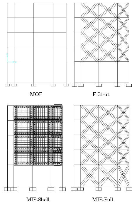
To serve the purpose of this study, an open frame model, refer to as MOF, was first made assuming the wall as nonstructural. The frames dimensions were determined by trial and error to satisfy all strength requirements and to obtain steel ratio between mini-mum and maximini-mum values. In the second model, refer to as MIF-Strut, the walls above basement level were considered structural and modeled as equiva-lent diagonal strut. The dimensions of the frames were the same as those of MOF. From the two models, the strength and rigidity enhancement of the structure due to infill wall can be observed through the forces and stresses in the frames, and lateral displacement of the two models. In the third model, refer to as MIF-Shell, the walls above base-ment were modeled as shell elebase-ment, as an alterna-tive of diagonal strut model. The size of frames in
this model was also the same as those of the second model. The interface between frame and wall was modeled using gap or link element [9]. This model will allow comparison of the two infill wall models in term of lateral stiffness and force distribution. From the third model, the stresses in the wall can be directly found through the stress contour.
Finally, a fourth model, MIF-Full was developed by adding wall to MIF-Strut at basement level. This ideal model will reveal the effect of wall discon-tinuity. It is important also to note that the story height at basement level was 5 meter while the height for the upper levels was 3.5 meter. The taller column at basement level may also contribute to the soft story problem if such problem exists.
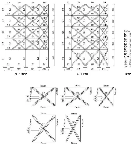
For the diagonal strut model, six cross diagonal struts were used following the model suggested by Chrysostomou et al.[15] as shown in Figure 2, in which only three strut are considered active for each lateral load direction. The analysis is made possible using compression only (tension limit) feature in SAP2000 v.15 [15]. The multi-strut model (instead of single strut) was chosen as it will be more appropriate to consider the effect of wall and frame interface on the force distribution in the beams and columns [6,12].
The equivalent width of the diagonal strut, Wef is calculated using Equations 1 and 2, proposed by Mainstone for single strut model [2].
inf model, the center strut area is equal to half the area of single strut (Ams) and the other half is divided equally for the two side struts (Figure 2 right).Figure 2. Multi-strut Model (left) and Area of Center and Side Struts (right)
Dimensions and Material Properties
The geometrical models for open frame and infilled-frames in x-direction, extracted from 3D models, are shown in Figure 3. The story height is 3.5 meters for the 1st– 4th floor and 5.0 meters for basement. The
beam span varies between 2.7 and 4.3 meters, and distance between frames are 4,5 meters (Figures 1 and 3). The total wall thickness is 200 mm and slab thickness of 120 mm is used with secondary beam in longitudinal direction.
The dimensions of frames and strut are shown in Figure 4. The columns for the upper levels vary from 200/650 at first floor to 200/200 at roof level. For the basement level, column size of 300/650, 500/500, and 300/300 are used as an attempt to increase the stiffness of this story. For the first floor level, a beam size of 300/500 is used in both directions. For the upper floor levels, the transverse beam size is 250/350 and the longitudinal beam size is 300/400. All dimensions are in mm. The beam sizes were kept the same for all models.
From the geometry and dimension of frame and wall, the total width of single strut obtained from Equations 1 and 2, varied between 400–664 mm (bottom part of Figure 4).
MOF F-Strut
MIF-Shell MIF-Full
The smaller number is for the narrower wall with smaller column. The number is then divided into 3 struts. The thickness of the strut is the thickness of the wall.
Concrete elastic modulus, Ec, is based on concrete compressive strength, f’c of 20 MPa. The infill wall
elastic modulus, Ei, is based on infill wall strength, fi
of 4 MPa. The two numbers for concrete and infill wall strength are assumed values, based on test results reported by others. As comparison, infill wall compressive strength value of 3.71 MPa [10] and 5 MPa [17] were reported. The tensile and shear strength of infill wall can be determined from its compressive strength, Agarwal and Shrikhande [13]
suggest that the tensile strength of infill wall ranges between 0.34 and 3.4 MPa. In this study, a value of 0.4 MPa is used. The diagonal tensile strength (shear strength) was calculated using Equation 3 [13].
fdt = k x (f’m)0,.5 (3)
fdt is diagonal tensile strength of brick masonry in diagonal tension, in psi, k is constant factor with values ranges between 2.5 and 4.5, f’m is the compressive strength of brick masonry prism, in psi. Using k of 2.5 and f’m of 4 MPa (592 psi), the corresponding value of fdt is 0.4 MPa (60,8 psi).
MIF-Strut MIF-Full Dimension
For the infilled-frame model using shell element, the interface between frames and walls are modeled using gap or link element to simulate the frame-infill wall interaction. The length of link element is taken as half the beam or column height to connect bet-ween frame element and shell element. The relation-ship between the infill stiffness, Ki, and gap stiffness,
Kg, are given by Equations 4 and 5 [6].
Kg = 0,0378Ki + 347 (4)
Ki = Ei.t (5)
With wall thickness, t of 200 mm, the stiffness of gap element becomes 17000 N/mm for all walls. This value is used to model the link element in the shell model.
Loads
The same loads are applied to all models, consisted of dead (D), live (L), and earthquake (E) loads using combinations of 1.2D + 1.6L for gravity load and 1.2D + 1.0L + 1.0E for lateral load. For the open frame model and infilled-frame model using strut, the weight of the infill wall is applied as distributed dead load to the beam under the wall and the weight of strut is set to zero. For the model using shell element, the weight of the infill wall is included in the self weight of the structure. A live load of 250 kg/m2 is applied directly to the RC slab modeled as
shell element.
For the earthquake load, equivalent static load method is utilized with some modification according to the site class C and response modification, R of 5 for non-ductile structure. The choice of equivalent
static load, rather than dynamic load, is to ensure that all models are equally loaded. The lateral loads are calculated using Equations 6 to 8 based on 2012 Indonesian seismic code [18].
Fx = Cvx.V for X-direction, and
Fy = Cvy.V for Y-direction (6)
∑ and
∑ (7)
V = Cs.W (8)
F is the lateral force, Cv is contribution distribution,
hi is the height of floor at i level, Wi is effective weight of floor at i level, value of k is constant value dependent of natural period, V is base lateral load, Cs is coefficient of quake response, and W is total effective weight of structure. For this model struc-ture the value for k was 1.6 and 1.4 for x and y direction, respectively, and Cs was 0.05.
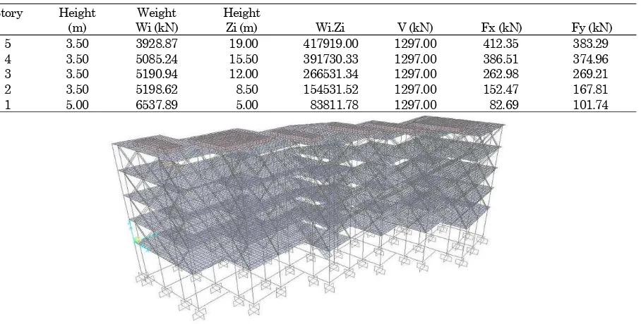
The summary of total lateral forces are shown in Table 1. Each force is then distributed equally to each frame at the same level.
The structures are modeled as linear elastic using commercial FE Program SAP2000 v.15. The frame reinforcement is designed following the ACI Code 318-2005 which is included in SAP2000 program [15]. Figure 5 shows the full 3D model of the infilled-frame structures using struts (MIF-Strut). Shown in the Figure that all components of the structure are included in the model. Beam, column, and strut are modeled using frame element. Floor and roof slab are modeled as shell element. Both ends of strut element are released against rotation.
Table 1. Summary of Total Lateral Forces
Story Height Weight Height
(m) Wi (kN) Zi (m) Wi.Zi V (kN) Fx (kN) Fy (kN)
5 3.50 3928.87 19.00 417919.00 1297.00 412.35 383.29
4 3.50 5085.24 15.50 391730.33 1297.00 386.51 374.96
3 3.50 5190.94 12.00 266531.34 1297.00 262.98 269.21
2 3.50 5198.62 8.50 154531.52 1297.00 152.47 167.81
1 5.00 6537.89 5.00 83811.78 1297.00 82.69 101.74
Results and Discussions
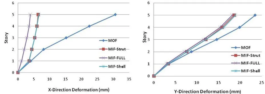
Analyses and design of four frame models show that the inclusion of infill walls in the frames model change the frames behavior significantly. Figure 6 shows the average lateral displacement at each floor level for all 3D models in X and Y directions. In the wall direction (left figure), deformation of top floor of MOF is more than 4.8 times larger than those of MIFs. This is a huge stiffness enhancement due to interaction between infill wall and frame. Perpen-dicular to the wall, however, the deformation of MOF is only 29% bigger than those of MIFs at the top floor (right figure) as there is no wall modeled in this direction. At the 1st floor level, MOF and MIFs with
open basement show lateral deformation of 4.04 mm and 3.50 mm, respectively, while deformation of MIF-Full is only 1.14 mm.
It is apparent that, without the infill wall at base-ment level, the stiffness of the MIFs at that level is small and the presence of wall at upper level increas the stiffness of the upper level very significantly. When the wall is made continuous (MIF-Full) then the stiffness of the frame increases at all levels. At the 2nd and higher floor levels, the deformation line of
MIFs with open basement is parallel to the line of MIF-Full. This means that discontinuity of infill wall at basement level reduces the stiffness at that level noticeably, which lead to a soft story mechanism.
The lateral displacement of strut and shell models are the same, except at the top floor that the defor-mation values are 6.4 and 6.6 mm for MIF-Strut and MIF-Shell, respectively. In general, both methods of modeling infill wall give similar deformation value.
In term of inter story drift, the deformations of all four model structures are shown in Figure 7. The left figure of Figure 7 clearly shows that the inter-story
drift of the infill wall models with open basement is the highest at the first floor level with ratio about 3.89 compared to that at second floor level. This soft-story mechanism is caused by discontinuity of infill wall at basement level combined with the bigger story height. It is apparent that the bigger column sizes at basement level are not enough to balance the stiffness of the infill wall. Despite the taller column at basement level, the open frame model does not show any soft-story mechanism, which means that if the infill wall at upper floor levels is not included in the models the problem could not be detected. It is also obvious that the drifts of infilled-frame with full wall (MIF-Full) are smaller than those of the other models at all floor levels. Interestingly enough, the soft-storey problem is solved with continuous wall.
The analysis results of the first two models, MOF and MIF-Strut, also show that the addition of infill wall to the open frame changes the force distribution in the frames and, accordingly, changes the stress distribution in the frame. Figure 8 shows the scaled stress S11 Max/Min (axial stress due to combined axial and bending moment) distribution in the frames of MOF and MIF-Strut due to lateral load combination of dead, live, and earthquake in the direction of wall (D + L + Ex). The stress distribution in the frame changes noticeably from MOF to MIF. The maximum stress values in column ends are 14.6 MPa and 11.8 MPa for MOF and MIF, respectively. The maximum stress values in beams were 7.6 MPa and 5.8 MPa for MOF and MIF, respectively. The smaller values of stresses correspond to the smaller axial forces and bending moment. Accordingly, less reinforcement is required in the wall direction. In the direction perpendicular to the wall, however, the steel requirements were comparable for both models. Complexity of the models made it difficult to quan-tify the reinforcement requirement for each model.
Figure 7. Inter Story Drift in X and Y-direction
MOF MIF-Strut
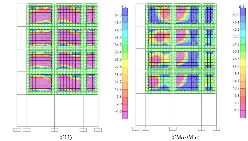
Figure 8. Stress S11 Max/Min Distribution in Frames due to Lateral Load Combination
(S11) (SMax/Min)
Stresses in the diagonal struts vary from floor to floor, with zero stress in tension struts. From stress diagram of MIF-Strut, it can be seen that the com-pressive stresses in the struts varies, with maximum values of 0.63 MPa at the first floor and 0.1 MPa at the top floor. Both values are much smaller than the infill wall strength of 4 MPa.
The infill wall stresses can also be obtained directly from the shell model, MIF-Shell, including tensile and shear stresses in the wall. Figure 9 shows the stress contour in the wall due to lateral load combination. The left figure shows internal stress S11 and the right figure shows principal stress Smax/min. Note that the stress contour in the left figure shapes like diagonal strut in compression. The diagonal shape is more obvious for single bay wall.
The maximum tensile stress obtained from MIF-Shell is 0.37 MPa and the average compressive stress is 0.1 MPa. The maximum tensile stress is less than the tensile strength of 0.4 MPa. The maximum stress Smax obtained from MIF-Shell is 0.38 MPa, which is only 60% of that obtained from the strut model.
The shear stresses S12, S13, and S23 are also available from MIF-Shell. In this case, the maximum value for shear is 0.26 MPa, which is also smaller than the shear strength of 0.4 MPa. It is apparent that, despite the different stress value obtained from strut and a shell model, the shell model provides much more information on the wall required for design purpose
Conclusion
Modeling of RC frame with infill wall as open frame (MOF) and infilled-frame (MIF) has lead to the following conclusions:
1. The infilled-frame models are more than 4.8 times stiffer than the open frame model when the lateral load is applied in the direction of the wall. If the load is applied perpendicular to the wall, however, the lateral stiffness of MIFs is 29% larger than that of MOF.
2. Normal stresses due to combined axial forces and
bending moment in the frames of MOF are significantly bigger than that of MIFs in the wall direction. Accordingly, less reinforcement is required for the frame. In the direction perpen-dicular to the wall, however, the steel require-ments are comparable for both models.
3. The stresses in the frames and infill walls are comparable deformation values. For wall stresses, however, strut model gives larger value than the shell model.
5. The soft-story mechanism can not be avoided in the absence of wall at basement level, regardless of the bigger columns dimensions.
6. Despite the more tedious process, the strut method can be applied for the design of frame with infill wall to ensure detection of any soft-story mechanism due to discontinuity of the wall.
In case of the building considered in this study, the basement and first floor plan of the actual structure is connected to a much stiffer structure that prevent soft-story problem.The full model, however, is not included in this paper. Further research is necessary to study the performance of infilled-frame structure under larger lateral loads to see the failure mecha-nism of each component of the frame. Further study on taller but simpler infilled-frame structure is also recommended.
Acknowledgement
This study has been possible with the support of the owner of Mantra Hotel and the hard work of young engineers at Vilamas.
References
1. Federal Emergency Management Agency, FEMA
306. 1998.Evaluation of Earthquake Damaged
Concrete and Masonry Wall Buildings. Basic
Procedures Manual. Prepared by: Applied Tech-nology Council (ATC-43 Project) 555 Twin Dolphin Drive, Suite 550 Redwood City, Califor-nia 94065. Prepared for: The Partnership for Response and Recovery Washington, D.C. Funded by: Federal Emergency Management Agency
2. Federal Emergency Management Agency, FEMA
273. 1997. NEHRP Guidelines for the Seismic Rehabilitation of Buildings (FEMA Publication 273). Prepared for the: Building Seismic Safety Council Washington D.C. Prepared by the: Applied Technology Council (ATC-33 Project) Redwood City, California. Funded by: Federal Emergency Management Agency Washington D.C.
3. SKBI 2.3.53.1987, Petunjuk Perencanaan Beton
Bertulang dan Struktur Dinding untuk Rumah dan Gedung.
4. Demir, F. and Sivri, M., Earthquake Response of
Masonry Infilled-frames, ECAS 2002
Internatio-nal Symposium on Structural and Earthquake
Engineering, October 14, 2002, Middle East
5. Korkmaz, K.A., Demir, F., and Mustafa S.VR., Earthquake Assessment of R/C Structures with Masonry Infilled Walls, International Journal of Science & Technology, 2(2), 2007, pp.155-164.
6. Vaseva, E., Seismic Analysis of Infilled R/C Frames with Implementation of a Masonry Panel Models, 11th National Congress on Theoretical
and Applied Mechanics, 2-5 Sept. 2009. Borro-vets, Bulgaria, 2009.
7. Doudoumis, I.N., Finite Element Modelling And
Investigation of the Behaviour of Elastic Infilled
Frames under Monotonic Loading,
Engineer-ing Structures, 29, 2007, pp. 1004-1024.
8. Asteris, P.G., Finite Element Micro-Modeling of
Infilled-frames, Electronic Journal of Structural Engineering, 8, 2008, pp. 1-11.
9. Dorji,J., Seismic Performance of Brick Infilled RC Frame Structures in Low and Medium Rise Buildings in Bhutan. Thesis for Master Degree at Queensland University of Technology, 2009. 10. Imran, I. and Aryanto, A., Behavior of Reinforced
Concrete Frames In-Filled with Lightweight Materials under Seismic Loads, Civil Engineer-ing Dimension, 11(2), September 2009, pp. 69-77.
11. Akpinar, U. and Binici, B., The Effect of Infilled Wall Collapse on the Deformation Estimations of Reinforced Concrete Frames, Journal of Civil
Engineering and Science, 2(3), September 2013,
pp. 171-177.
12. Bell, D.K. and Davidson, B.J., Evaluation of
Earthquake Risk Buildings with Masonry Infilled Panel, NZSEE 2001 Conference, Paper No. 4.02.01.
13. Agarwal, P. and Shrikhande, M., Earthquake
Resistant Design of Structures. PHI Learning Pvt Ltd., 2006, Eastern Economy Edition.
14. Grundy, P., The Padang Earthquake 2009 –
Lessons and Recovery, Australian Earthquake
Engineering Society 2010 Conference, Perth,
Western Australia.
15. Chrysostomou, C.Z, Gergely, P., and Abel, J.F., A Six-Strut Model for Nonlinear Dynamic Analysis of Steel Infilled Frames, International Journal of Structural Stability and Dynamics, 2(3), September 2002, pp. 335-353.
16. Computer and Structures Inc., CSI, Analysis Reference Manual for SAP2000®, ETABS®,
SAFE® and CSIBridge™.
17. Mondal, G. and Jain, S.K., Lateral Stiffness of Masonry Infilled Reinforced Concrete (RC) Frames
with Central Opening, Earthquake Spectra,
Earthquake Engineering Research Institute, 24(3), August 2008, pp. 701-723.
18. Badan Standardisasi Nasional. 2012. Tata Cara
Perencanaan Ketahanan Gempa untuk