A STUDY ON PATTERN DAMAGE OF FINGER JOINTS IN BAMBOO
LAMINATED BEAMS
Agus Rivani **
Abstract
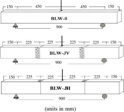
The aim of this study was to know the pattern damage of finger joints in bamboo laminated beams. The dimension of laminated beams were manufactured in 1200 mm length, 140 mm deep and 50 mm wide, which consisted of horizontally laminate of 5 mm in thickness. The finger joint consisted of two variations that were horizontal and vertical directions. One variation of other beam was manufactured in the form of clear straight beams as comparator parameters. The bending shear test was conducted with a three-point static bending.
The result of research indicated that the joint areas, which the parameter of glue spread have to influence on the strength. Consequently, degradation of strength occurs on all of adhesive jointed beam can reach 48%, while the optimum strength of jointed beams can reach 82% of clear straight beams. This research identify that the pattern damage of laminated beams tends on a mixed mode failure between tension and compression. The strength of vertically finger joint more effective than horizontally finger joint.
Keyword:seismic, Preserved Amplitude
*
Staf Pengajar Jurusan Teknik Sipil Fakultas Teknik Universitas Tadulako, Palu
1. Introduction
The bamboo usage has been widely seen in so many construction forms. As a construction material, they has been found in the tropical and sub tropical regions. The natural dimension, stem form limit, and many traditional joint types affected to their structural efficiency.
As with any other glued-wood product, the objective when finger jointing is to adhere the two pieces of wood together to render the joint strong enough under ultimate load so that failure occurs in the wood rather than in the adhesive (Sellers et al, 1988). Finger joints have been proven suitable for use in connections for wood trusses (Hoyle et. al., 1973), corner and multiple member furniture joints (Richards, 1962), laminated beams (Wibbens, 1989), truck decking, as well as a variety of other structural and non-structural applications. Proof
loading of end-jointed material has been
implemented in many instances to eliminate substandard joints (Forest Products Laboratory, 1999). One aspect that is critical to the performance of finger joints in service is the overall geometry of the joint.
This study makes available important information about the use of bamboo as a wood
suitable for finger jointing and shows how it compares with two important directions. One of the efforts to support bamboo application as universally construction material, which nowadays developed is lamination technique.
2. Materials and Methods
The bamboo used in this experiment is laminate. Resin application was about 60 gram per double glue line.
The glued bamboo laminate was put in between two steel plates with 8 mm in thickness. Five C-clips were used to add pressure to the beam mats. After pressed for 24 hours, the beams were trimmed to the target size of 1200 x 140 x 50 mm.
A Study On Pattern Damage of Finger Joints in Bamboo Laminated Beams
(units in mm)
Figure 1. Direction of load in the bending test for finger jointed and laminated beam
Figure 2. The three-point bending test apparatus
The equipments used in this experiment are circular saw, planner machine, hydraulic pressure, Universal of Testing Machine, hydraulic jack, load cell and load indicator, dial gauge, rigid frame, and clamp set.
The method used here includes the experimental method. Preliminary test based on the standard procedure of ISO-1975. These tests includes the density, moisture content, tensile strength parallel to grain, compression parallel and perpendicular to grain, shear strength, modulus of rupture and modulus of elasticity.
The bending shear test was conducted in a three-point static bending. The bending test in this study defines flexural properties with three-point loading. The bending apparatus used was a 3-point loading setup (two load supports and one loading points) with a half shear span of 450 mm. The supports for the test apparatus were fixed knife-edge reaction with rollers. Response variables measured and calculated for each sample were modulus of rupture (MOR) and modulus of elasticity (MOE). The setting up of the test is shown in figure 2.
450 150
150
900
450
225 225
225 150
150
900
225
225 225
225 150
150
900
225
Loading Frame
Load cell Transducer Indicator
Laminated Beam 900 mm
Laterally support Point of
loading
18
Conseqently the moisture content depends on the surrounding climate and changes accordingly. The density and moisture content of samples are shown in Table 1.
b.
The Mechanical Properties of BambooThe mechanical properties of Wulung bamboo are presented in Table 2.
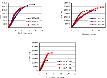
Relationship between load and vertical deflection of test results are presented in Figure 3.
3.3 Stiffness Factor of Laminated Beams
In general, stiffness factor value of clear straight beams (no joint) is larger than jointed beams. The stiffness factor of each beam is given in Tables 4.
Table 1. Density and moisture content of samples
Samples
Density (g/cm3) Moisture content (%)
Range Mean Range Mean Spesification (LPMB’61)
Bamboo stem 0.50-0.59 0.53 14.67-14.51 14.56 6-16
Laminated beam 0.60-0.62 0.61 12 - 14 13 6-16
Table 2. The mechanical properties of bamboo
Number of specimens
The comp.
// to grain
The comp.
┴ to grain The tension // to grain
The shear
strength MOR MOE
(MPa) (MPa) (MPa) (MPa) (MPa) (MPa)
1 40.69 7.11 148.74 5.73 74.34 14987.30
2 37.25 7.58 124.06 6.77 77.99 13765.78
3 38.94 6.80 153.85 5.39 72.32 13813.87
Mean 38.96 7.16 142.22 5.96 74.88 14188.98
Table 3. The strength ratio of laminated beams
Samples Ultimate Load “Pu” Pu/ (b.d)
kN kN/m2 mean Ratio
BLW-01 32.96 4709
4516
1
BLW-02 29.43 4528
BLW-03 28.45 4310
BLW-JV1 24.58 3512
3723
0.82
BLW-JV2 28.74 4106
BLW-JV3 24.86 3551
BLW-JH1 12.75 1889
2336
0.52
BLW-JH2 21.97 3139
A Study On Pattern Damage of Finger Joints in Bamboo Laminated Beams
Figure 3. The load versus vertical deflection in mid-span curve
Table 4. The stiffness factor of each laminated beam
Samples (EI)max Ratio
Between Groups 26980.736 2 13490.368 1.095NS 0.393
Within Groups 73934.718 6 12322.453
20
Elasticity (MOE)
The bending contribution determined by MOR and MOE. The result of MOR and MOE are given in Tables 6. The maximum MOR obtained by BLW-0, while percentage of MOR degradation in BLW-JV and BLW-JH are 21.10% and 49.80% to BLW-0.
The analysis of variance (ANOVA) for MOR (Tables 7) showed significant in one-way interaction. This indicated that difference of load direction given influence in bending strength. Inelastic behavior of materials was caused to
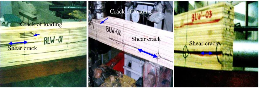
3.5. The Pattern Damage of Laminated Beams a. BLW-0
The pattern damage of clear straight beams (no joint) is shear failure between laminate and glue-line. In this case, it is started with a horizontally crack (initial crack) in laminates, then it happened crack in loading point. Finally, the laminated beam was damage to the support area, which shear stress is critical. Visually, the pattern damage of beams is given in Figure 4.
Table 6. MOR dan MOE of laminated beams
Samples MOR MOE
(MPa) Mean (MPa) Mean
BLW-01 45.41
45.50
3856 5882
BLW-02 47.02 7128
BLW-03 44.08 6663
BLW-JV1 33.87
35.90
2777 3339
BLW-JV2 39.60 2972
BLW-JV3 34.24 4268
BLW-JH1 18.89
22.84
4542 4758
BLW-JH2 30.27 4739
BLW-JH3 19.36 4993
Table 7. Result of variance analisys with ANOVAfor the MOR
Sum of
Squares df Mean Square F* Sig.
Between Groups 776.437 2 388.219 21.604S 0.002
Within Groups 107.819 6 17.970
Total 884.256 8
Note: * 0.05 Level of significance, S shows significant effect or interaction
Table 8. Result of variance analisys with ANOVAfor the MOE
Sum of Squares df Mean Square F Sig.
Between Groups 9746230.889 2 4873115.444 3.806S 0.086
Within Groups 7682968.667 6 1280494.778
Total 17429199.556 8
A Study On Pattern Damage of Finger Joints in Bamboo Laminated Beams
Figure 4. The pattern damage of BLW-0
Figure 5. The pattern damage on BLW-JV
Figure 6. The pattern damage of BLW-JH
b. BLW-JV
The pattern damage of vertically finger-jointed beam is shear failure in laminates before broken at joint. It is started with a horizontally crack in laminate, and then happened crack in loading point. The pattern damage of joint expands to follow line inclination of finger joint. Shear failure was dominated in the mid-span until to the support area. Finally, laminated beam suddenly broken in finger jointing. The pattern damage of
laminated beams is presented in Figure 5.
c. BLW-JH
The pattern damage of beam with
horizontally finger joint is bending failure at joint. It is started initial crack in horizontal direction. There is no crack in loading-point like other beam. The laminated beams are spontaneously broken at the joint. The pattern damage of laminated beams is seen in Figure 6.
Shear crack
Crack of loading
Shear crack
Crack of loading
Shear crack
Shear crack Crack of loading
Crack of loading
BLW- JV2
Shear crack
Joint Failure
Shear crack
Crack of loading
Joint Failure Joint Failure
Joint Failure Joint Failure
22
grading of the laminations, the quality of finger joints, glue line integrity and quality control.
There were three response variables, the stiffness factor, MOR, and MOE measured for each sample in the bending test that was used for statistical analysis. The analysis of variance (ANOVA) for the MOR and MOE showed significant one-way interaction or effect.
Forest Products Laboratory, 1999, Wood
Handbook--Wood as an Engineering Material, General Technical Report FPL-GTR-113, USDA Forest Service, Forest
ProductsLaboratory, Madison, WI, 463 p.
LPMB, 1961, Peraturan Konstruksi Kayu
Indonesia NI-5 PKKI-1961, Yayasan Penyelidikan Masalah Bangunan, Bandung.
Richards, D. B, 1962, High-Strength Corner Joints
for Wood, Forest Products Journal 12(9): 413-418.
Sellers, T., Jr., J. R. McSween, W. T. Nearn, 1988,
Gluing of Eastern Hardwoods: A Review, General Technical Report SO-71, USDA Forest Service, Southern Experiment Station New Orleans, LA, 30 p.
Wibbens, R. P, 1989, Glued Laminated Timber,
Concise Encyclopedia of Wood and Wood Based Materials, A. P. Schniewind. Ed,