LOAD CURRENT CONTROL BASED ON LUENBERGER
OBSERVER FOR THREE PHASE POWER CONVERTER
SVPWM
1HARI SUTIKSNO,2MOCHAMAD ASHARI, 3MAURIDHI HERY PURNOMO
1,2,3
Department of Electrical Engineering
Sepuluh Nopember Institute of Technology (ITS), Surabaya-Indonesia 1
Department of Electrical Engineering
Sekolah Tinggi Teknik Surabaya (STTS), Surabaya, Indonesia
E-mail: [email protected]
,
2,
3ABSTRACT
This paper presents Load Current Control based on Luenberger Observer for Three-Phase Power Converter SVPWM with current regulation. The use of observer is intended to replace the use of dc current sensor, so it eliminates the nonlinearity problem and drop voltage caused the sensor. This research develops a controller to improve the time response of the dc output voltage of the three-phase power converter based on load current estimation. The simulation results show that overshoot the output voltage on load change from full load to 50% full load is about 3% with settling time 0.03 sec. .
Keywords: Observer, Power converter, Current Regulator, Space Vector, Pulse Width modulation
1. INTRODUCTION
Three phase power converter is widely used in industrial application because it has many advantages including unity power factor, low ripple of the DC voltage and low total harmonic distortion Some researchers have developed the direct power control methods to avoid the use of sensors and to improve the time response of three-phase converter that is caused by load variation [1], [2].
Abdelmalek B, Hossin B, and Hind D [3] developed a controller based on virtual flux called direct power control. The simulation results showed that the output voltage response has overshoot 15V from full load to 50% full load at 620V rated voltage with settling time 0.1 sec. Abdelouahab B, Jean-Paul G, and Fateh K developed a switching table for Direct Power Control of three-phase PWM rectifier [4]. These experiment results showed that the overshoot is about 8 volt with settling time 0.8 sec at rated voltage 120V and the load change from 50% to 100% full load. Other approaches often, linear proportional–integral (PI) compensators are implemented for voltage regulation and parameterized for a linearized model of the plant. Usually, the load is modeled as a resistor or a
constant current source [4] . Other approaches have used an alternative modeling of the load as a constant power sink. However most of the papers has not shown the time response at start.
The implementation of SVPWM (Space Vector PWM) on three-phase power converter is still used up till now since this technique has several advantages such as low harmonic distortion, high efficiency and bidirectional power flow [5],[6],[7].
This paper proposes a Luenberger observer for three-phase power converter SVPWM to estimate load current with current regulator with simplified model. This observer can guarantee linear error dynamics so that the convergence of the estimation error is exponential and better time response due to the load change This paper is organized as follows. In section 2, the three-phase power converter with current regulation is described. In section 3, a Luenberger observer for estimating the load current is designed on Three-Phase Power Converter SVPWM. Performance evaluation, discussion and tests are presented in Section 4. Finally, conclusions are drawn in Section 5.
2. THREE-PHASE POWER CONVERTER
WITH CURRENT REGULATION
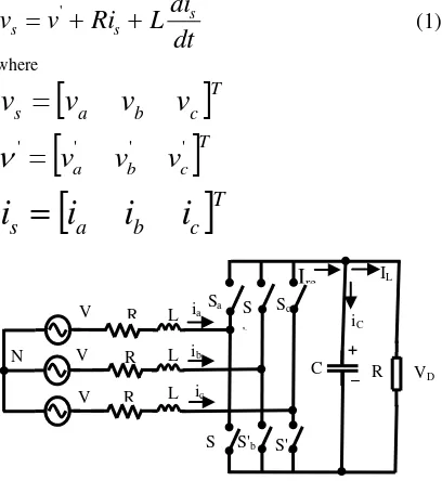
2.1 Three-Phase Power Converter model Relationship between voltage and line current of the main three-phase power converter circuit shown in figure 1 and can be expressed as the equation bellow
dt
i
d
L
i
R
v
v
s ss
=
+
+
'
(1)
where
[
]
Tc b a
s
v
v
v
v
=
[
]
Tc b
a
v
v
v
' ' ''
=
ν
[
]
Tc b a
s
i
i
i
[image:2.612.92.296.365.587.2]i
=
Figure 1: Main Circuit of Three-Phase Power Converter
Next, relationship between converter voltage on input side and DC voltage on output side with switch position as parameter is as follows.
DC c b a ' v t S t S t S t v − − − − − − = ) ( ) ( ) ( 2 1 1 1 2 1 1 1 2 3 1 )
( (2)
Equation that shows the relationship between converter current irect and line current is is as follow
[
a b c]
srect
S
t
S
t
S
t
i
i
=
(
)
(
)
(
)
(3) Equation (1) shows that amplitude and line currentphase can be arranged through voltage setting v’, and the magnitude of this voltage is a function of switch position Sa, Sb, and Sc as well as DC voltage. On output side (load side) the relationship between load current, rectifier current and DC voltage is as follows: L DC rect
i
dt
dv
C
i
=
+
(4) Equation (4) shows that the magnitude of DCvoltage is influenced by load current iL: and rectifier current I rect. Substituting equation (3) into equation (4) results in the relationship that DC voltage response on load change can be controlled through the combination of the position of switches
Sa, Sb, and Sc.
Space Vector PWM technique is an algorithm to control PWM pulses for three-phase alternating voltage generation with the purpose of reducing total harmonic distortion with high efficiency. If a three-phase power converter which is expected to produce voltage on AC side is in accordance with reference voltage, the reference signal is expressed by space vector with transformation abc-αβ. From the transformation result, duty cycle for every state combination of switch Sa, Sb, Sc is determined.
2.2 Current Regulator
Current regulator functions to control voltage through the line current setting [9]. This input current is expected to be in phase with its source voltage or + − = = ) 3 2 sin( ) 3 2 sin( ) sin( ) ( ) ( ) ( ) ( π ω π ω ω t V t V t V t v t v t v t v m m m c b a s and + − = = ) 3 2 sin( ) 3 2 sin( ) sin( ) ( ) ( ) ( ) ( π ω π ω ω t I t I t I t i t i t i t i m m m c b a s L L L
Sa S b
Sc
S S'b S'c
It can simply be written as is(t) = u.vs(t). To realize that relationship, the voltage converter on phase angle on generated AC side meets the relationship as seen in figure 2. If resistance in inductor is not neglected, reference voltage can be determined based on instantaneous current voltage and instantaneous current source as:
) ( ) ( ) ( ) ( ) 2 1 ( ) (
'
t I T
L R T t I T uL t v T
uL t
v
s s
n s n s s n
ref = − − − − + (5)
[image:3.612.97.285.277.386.2]where Ts is sampling interval and u is given control. Control signal
u
(
t
n)
=
I
mV
mis
to obtain the line currents, which is in phase with the voltage source and the amplitudeIm = u Vm.Figure 2: Phasor diagram of voltages and input current
Figure 3 shows that control signal is used to generate reference voltage Vabc ref, and then control pulses Sa, Sb, Sc are produced through SVPWM algorithm. The changes of load resistance did not result in changes in the input current, because input current amplitude is only determined by the control signal u .
Figure 3: Plant of three-phase Power Converter SVPWM
2.3 Observer
Control of DC voltage on the load changes can be done by using a controller that utilizes feedback signals from voltage or current DC from the converter. If the DC current is used as the feedback signal, the use of state observer will make
it possible to obtain the estimation of the load current so that the DC current sensor is not required. In general, for a plant stated in the linear model approach, the state equation can be expressed as
u
x
=
Ax
+
B
(6)
Cx
y
=
(7)where u is control signal (input), y is the output and x is the state from the plant.
Fig.4 shows the Luenberger Observer scheme. Luenberger observer consists of linear model from a plant with the input u and output ŷ that is a part of duplication from the real plant in program; and feedback element with input signal from the difference between the output signal ŷ and the plant output signal y. Mathematically, it can be expressed as in [10]:
)
ˆ
(
ˆ
ˆ
A
x
B
x
x
=
+
u
+
L
y
−
C
(8) Selection of L strengthening is based on eigenvalues of the matrix A-LC.Figure 4: Luenberger Observer Scheme
3
.
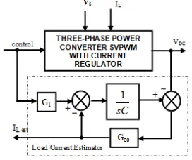
OBSERVER DESIGN FOR THREE-PHASE POWER CONVERTER SVPWM [image:3.612.91.294.514.624.2]Figure 5 shows a controller design of a plant of three-phase Power Converter SVPWM with current regulator, the estimation of feedback signal is in the form of DC current using state observer. Load current in the diagram is described as a signal disorder that affects the output DC voltage magnitude of the power converter.
[image:3.612.348.484.595.709.2]Converter model can be expressed in the form of simple equation as the relationship between the input power, the power stored in the capacitor and the output power as
)
(
)
(
)
(
t
p
t
p
t
p
out=
in+
C (9) where)
(
2
3
)
(
)
(
3
)
(
t
v
t
i
t
V
2u
t
p
in=
=
m (10))
(
)
(
)
(
t
V
t
i
t
p
o=
DC DC (11)dt
t
dV
t
CV
t
i
t
V
t
p
DCDC C
C C
)
(
)
(
)
(
)
(
)
(
=
=
(12)From equation (9), (10), (11) and (12), we obtain the following
] ) (
) ( 2 3 ) ( [ 1 )
( 2
t V
t u V t i C dt
t dV
DC m DC
DC = + (13)
In a feedback control system, the output voltage of the converter will have a relatively small variation around the working voltage (VDCO). It is possible to simplify equation (13) into
)]
(
)
(
[
1
)
(
1
u
t
G
t
i
C
dt
t
dV
DC
DC
=
+
(14)
where
DC m
V
V
G
2
3
21
=
Hence, from the equation state (6) matrix A=0,
B=G1. While for equation (7) the value C is equal to 1/C (C=capacitance of the power converter). In Figure 5, feedback signal e is not fed together with
u, but to the point after signal u obtaining G1
strengthening. It means that summing point is the point where the capacitor current is the reduction result of a rectifier current irect minus load current IL (estimation). L Strengthening must consist of proportional and integral values or it is expressed as:
∫
+
=
K
e
t
K
e
t
dt
I
Lest p(
)
i(
)
(15)
At steady state, the signal error ess = 0, so the
integrator will hold the load estimation current.
4. SIMULATION RESULTS
The parameter of three-phase power converter simulated is shown in table 1. In the simulation, observation of the dynamic state of estimation
[image:4.612.87.296.159.287.2]current was done, where load changes (from full load RL=60 Ω to load with RL=240Ω) occurred at time t=0.3 seconds. Fig. 6 is the simulation diagram of three-phase power converter control SVPWM system with current regulator as plant.
Table 1 Power Converter Parameters
Parameters Value
Peak Phase Voltage 100 V
Frequency 50 Hz
DC Voltage 300V
Inductance of reactor 3mH
Internal Resistance 0.2 ohm
Capacitance 1000uF
Resistance on Full Load 60 ohm
Sampling Frequency 10kHz
[image:4.612.325.505.165.289.2]In this simulation, observation on load current (DC) as a result of estimation of dynamic state was done. To guarantee DC voltage variation experienced small variation, controller role in feedback system must be functioned.
Figure 6: Simulation diagram of the proposed system
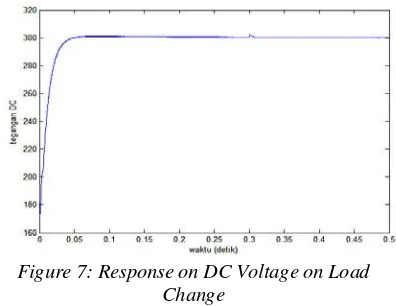
[image:4.612.316.510.364.465.2]Figure 7 shows that after heading to the working voltage (300V), the changes of converter DC voltage to the load changes in the simulation had a relatively small variation (less than 1%).
Figure 7: Response on DC Voltage on Load Change
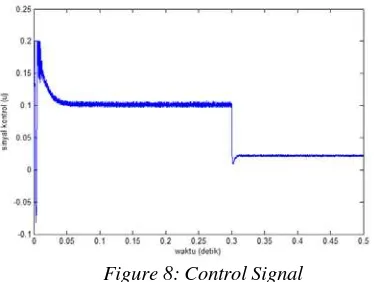
[image:4.612.321.519.552.705.2]for a capacitor voltage charging to 300V with maximum value of u = 0.2 or input current amplitude of 20 A. At an interval of 0.05 to 0.3
seconds, the control signal u = 0.1 (Im = 10A) to keep the DC voltage 300 V at full load (RL = 60 ohms), and after time t = 0.3 sec, u = 0.025 (Im =
2.5A) to keep the voltage at the load with resistance
[image:5.612.93.284.194.335.2]RL = 240 ohms.
Figure 8: Control Signal
Figure 9 shows that load current estimation at the time of transition from 0 to 0.05 seconds experienced a large difference. This is because at the time, the DC voltage experienced transition in the form of an increase of 173 V into 300 V, so that the estimator did not give precise results. At full load, estimation current was around 5A (from 0.05
[image:5.612.96.280.468.625.2]to 0.3 seconds) in accordance with the load current While at load of RL = 240 ohm, the load current estimation gave a similar result (1.25A).
Figure 9: Load Current Estimation
5.
CONCLUSION
The conclusions that can be drawn, among others, are as follows: The estimated load current using a state observer can avoid the use of load current sensor. Simplification of the observer model could be made by maintaining DC voltage variations caused by load changes was small. The time response of the output voltage at start is small (about 0.05 sec). The good response can be tuned
manually by tuning the proportional and integral parameters of controller.
REFRENCES:
[1] Antoniewics, P. Kazmierkowski, “Predictive direct Power Control of Three-phase Boost Rectifier”, Bulletin of the Polish Academy of Sciences, Vol 54, No.3, pp.287-292, 2006 [2] Zheng Zheng; Cong Wang; Haijun Tao,
“Research On Three-Phase PWM Rectifier Based On Predictive Control” , ICIT 2008. IEEE International Conference On Industrial Technology pp.1-3, 21-24 April 2008 [3] Abdelmalek Boulahia, Hocine Benalla, Hind
Djeghloud, “Direct Power Control (DPC) of Three Phase PWM Rectifiers”, Laboratoire d’Electrotechnique de Constantine
[4] Abdelouahab Bouafua, Jean-Paul Gaubert, Fateh Krim, Abdelmadjid Chaoui, “Unity Power Factor Operation of Three-Phase PWM Rectifier Based on Direct Power Control”, The International Conference on Computer as a Tool EUROCON 2007, Warsaw, September 9-12, p 1518-1523 [5] Hari Sutiksno, Maurice Fadel, Yanuarsyah
Haroen, Mochamad Ashari., Mauridhi Hery Purnomo, “Load Current Control For Three-Phase Power Converter SVPWM With Current-Regulation”, Power Electronics and Motion Control conference (epe/pemc), 2010 14th international, pp.191-195,6-8 Sept 2010. [6] Rathnakumar. D., Lakshmana Perumal J.,
Srinivasan T., A New Software
Implementation Of Space Vector PWM, Southeastcon, 2005, Proceeding IEEE, pp.131-136, September 2002.
[7] Kocalmis, A., Sunter, S., Simulation Of A Space Vector PWM Controller For A Three-Level Voltage-Fed Inverter Motor Drive,
IECON 2006-32nd Annual Conference On IEEE Industrial Electronics. pp. 1915–1920, 6-10 Nov. 2006.
[8] Min, B.-D., Youm, J.-H., Kwon, B.-H,”SVM-Based Hysteresis Current Controller For Three-Phase PWM Rectifier”, Electric Power Applications, IEE Proceedings, Vol 146, Issue 2, Pp. 225–230, , March 1999.
[9] Saetieo, S.; David Torrey,”Fuzzy Logic Control Of A Space-Vector PWM Current Regulator For Three-Phase Power Converters”, IEEE Transactions On Power Electronics, Vol.13, Issue 3 Pp.125-133, May 1998.