OPTIMIZING TERRESTRIAL LASER SCANNING MEASUREMENT SET-UP
Sylvie Soudarissanane and Roderik Lindenbergh
Remote Sensing Department (RS)) Delft University of Technology Kluyverweg 1, 2629 HS Delft, The Netherlands (S.S.Soudarissanane, R.C.Lindenbergh)@tudelft.nl
http://www.lr.tudelft.nl/rs
Commission WG V/3
KEY WORDS:Laser scanning, point cloud, error, noise level, accuracy, optimal stand-point
ABSTRACT:
One of the main applications of the terrestrial laser scanner is the visualization, modeling and monitoring of man-made structures like buildings. Especially surveying applications require on one hand a quickly obtainable, high resolution point cloud but also need observations with a known and well described quality. To obtain a 3D point cloud, the scene is scanned from different positions around the considered object. The scanning geometry plays an important role in the quality of the resulting point cloud. The ideal set-up for scanning a surface of an object is to position the laser scanner in such a way that the laser beam is near perpendicular to the surface. Due to scanning conditions, such an ideal set-up is in practice not possible. The different incidence angles and ranges of the laser beam on the surface result in 3D points of varying quality. The stand-point of the scanner that gives the best accuracy is generally not known. Using an optimal stand-point of the laser scanner on a scene will improve the quality of individual point measurements and results in a more uniform registered point cloud. The design of an optimum measurement setup is defined such that the optimum stand-points are identified to fulfill predefined quality requirements and to ensure a complete spatial coverage. The additional incidence angle and range constraints on the visibility from a view point ensure that individual scans are not affected by bad scanning geometry effects. A complex and large room that would normally require five view point to be fully covered, would require nineteen view points to obtain full coverage under the range and incidence angle constraints.
1 INTRODUCTION
The available mid-range 3D Terrestrial Laser Scanners capture the 3D positions of a scenery with data acquisition of unprece-dented speed, with accuracies in the order of millimeters. The scanner provides a 3D visualization of a scene by measuring dis-tances to object surfaces in a spherical coordinate system. For each point, it records a horizontal and a vertical angle, and a range measurement from the hit point on the surface to the scan-ner, with the center of the scanner as the origin of a local co-ordinate system. The reflection of the laser beam on the object surface is used to acquire a range measurement as well as an in-tensity value of the reflected light (Vosselman and Maas, 2010). Although the point measurements are accurate, scans are sub-ject to measurement noise. Manufacturers often provide technical specifications including accuracy of measurements performed on reference surfaces under laboratory conditions (Faro, 2010; Le-ica, 2010). Manufacturers accuracy specifications are often set without regard to the inherent variability that exists in the hard-ware (Dorninger et al., 2008; Kersten et al., 2004; Lichti, 2007), in the atmospheric conditions (Hejbudzka et al., 2010; Borah and Voelz, 2007; Hoefle and Pfeifer, 2007; Voisin et al., 2007), in the object properties (Kaasalainen et al., 2009; Bucksch et al., 2007) or in the scanning geometry (Soudarissanane et al., 2011; Schaer et al., 2007).
Systematic and random errors of individual point measurements propagate through standard processing steps to the final prod-ucts like 3D as built models or structural monitoring results. In Soudarissanane et al. (2011), an original approach is presented to model the scanning geometry effects by focusing on the inci-dence angle and the distance to an object’s surface. It is shown that by considering the influence of the distance on the signal to noise ratio, the increase in measurement noise with increasing
incidence angle and range could be successfully modeled.
Several scans taken from different view points are needed to have a full coverage of the object surface and to avoid major occlu-sions. Under stable atmospheric conditions, large variability is observed in individual points produced during surveys consisting of several scans taken from different locations around an object. In practice, most scenery contains a large variety of materials and different parts of the scenery are scanned with a different scan-ning geometry from several view points. The Terrestrial Laser Scanner is a remote sensing technique commonly used for more than a decade in a wide range of engineering applications, such as geodetic survey, civil engineering, forestry, forensics or cultural heritage. Despite the large variety of applications, the optimal view point placement for an accurate and reliable acquisition has not yet been investigated. In this paper, it is shown how scanning geometry constraints can be exploited to improve the measure-ment set up. By defining an optimal scanner view point in the scenery, a spatial coverage of good quality is ensured. Moreover, the definition of the minimum number of view points needed to cover an object or an area is investigated. This optimal measure-ment set up definition allows the acquisition of accurate data that can be further processed with a smaller propagation of errors.
2 PLANNING VIEW POINT POSITIONS
polygons or tetrahedrons. Almost all 3D indoor scene can be re-duced to a 2D map by taking an horizontal cross section of the scene at for instance the height of the sensor. This approximation of the 3D surrounding as a 2D map results in less intensive com-putations. Moreover, this 2D map may include holes that can be caused by e.g. walls, furniture in the room, columns. The hori-zontal cross-section enables to visualize a floor map at the height of the scanner, with holes consisting of non-transparent objects in the scene, as depicted in Fig. 1.
Local sequence of scans obtained to cover an entire 3D scene of-ten yield in abundant number of scans, in most cases redundant, with too many overlapping areas or with bad scanning geome-try. As each acquisition costs a significant amount of time, a minimum number of scan locations is desired to cover the scene. Moreover, post-processing steps such as the registration are af-fected by the number of acquisitions in a scene. On one hand, too little acquisitions and far apart might result in scans that can-not be registered due to insufficient overlap. On the other hand, too many scans are computationally intensive to register in one common coordinate frame. A trade-off between the number of acquisitions and the computational efforts needs to be defined. In the past years, several point cloud registration methods have been developed. Existing approaches to register point clouds are based on two main techniques. The first technique incorporates tie points that are common in two point clouds, and estimates transformation parameters by minimizing the distance between the corresponding tie points (Besl and McKay, 1992). The sec-ond technique relies on the adjustment of correspsec-onding surface geometry based on surface normal estimation (Gruen and Akca, 2005; Gorte et al., n.d.; Vosselman et al., 2004; Khoshelham and Gorte, 2009). In both approaches, samples of the surface need to be acquired with good quality to estimate a tie point location or a surface normal. The registration quality is highly dependant on the quality of the measurements. In this paper, we assume that the scans will be registered using the adjustment of surface cor-respondence, such as the method proposed by Gruen and Akca (2005).
Ideally, the solution of this problem would allow to scan and cover the entire scene from a predefined number of view points. The determination of the positions of the view points to scan all the visible surfaces is a well-studied problem in computer and machine vision, known as the Art Gallery problem (Chvatal, 1975; O’Rourke, 1987) or the Next Best View problem (Reed and Allen, 1999; de Berg et al., 2008). Generally, these algorithms determine the next location to place the scanner to maximize the amount of information to be captured that will be added to the already present one. These algorithms generally assume the sens-ing instrument to be perfect, with an infinite field of view, with precise point measurements under any incidence angle or range constraints and with almost instant acquisition times. These solu-tions are very general and are often unsuitable for the actual scan-ner capabilities in a real world situation. In practice, the scanscan-ner has range limitations set by the manufacturer, both with a min-imum distance and a maxmin-imum distance of measurements of a surface. Furthermore, it has been shown in Soudarissanane et al. (2011) that high incidence angles deteriorate the quality of mea-surements, therefore a constraint on incidence angles is added to ensure a good quality of acquisition.
To significantly reduce the number of scans to cover an entire scene and ensuring good quality scans, we propose an optimal view point localization method based on a map of the area and scanner constraints. This method comprises the following con-straints:
•The map is a horizontal cross-section obtained at the height of
the scanner. This 2D map may include holes,
•The scanner has a range limitations defined by the manufac-turer,
•The incidence angles measured on surfaces should not exceed a defined threshold.
To solve this optimization problem under the above mentioned constrains, the following requirements should be fulfilled: 1−All edges of the 2D map are covered by at least one view point
2−All edges are covered from at least one view point with at least a minimum distancedmin and with a maximum distance
dmaxto the scanner
3−All edges are scanned from at least one view point with an incidence angles below a maximum incidence angleα.
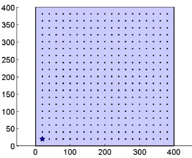
To define the optimal view points, the interior of the scene needs to be sampled with potential view point locations. The room is discretized and gridded with predefined steps of possible scanner locations, as depicted as an example in Fig. 3(a). This discretiza-tion has the advantage of less computadiscretiza-tions than considering con-tinuous locations. However, the grid step size needs to be well defined to avoid any conflicts with the set constraints, i.e. mini-mum distancedminand maximum distancedmax. Too large grid
will result in very fast computations, but less accurate optimal positions. Too small grid increase the processing time with no guarantee of having a better location.
2.1 2D Visibility Polygon
The scene is defined as a 2D map consisting of a simple outer bound polygonPoandKsimple holes polygonsPhj, j= 1...K. As defined by de Berg et al. (2008), a simple polygon is a closed polygonal chain of line segments that does not intersect itself. The interior and the exterior of a simple polygon is well-defined. Holes are interior obstructions caused by e.g. walls, furniture in the room, columns.
To define potential view point locations, the interior of the room is sampled such that a view pointOiis defined inside Po and outside allPhj. This room is gridded withnpossible view point locations, denoted asOi, i= 1...n. The grid step is defined so
that each edge part can be visible from at least one view point.
The definition of the 2D visibility polygonVifrom the view point
Oiis a well-studied problem (Erdem and Sclaroff, 2006; Landa
et al., 2006; Obermeyer et al., 2010; Tomas et al., 2006). In this paper, the method described by Erdem and Sclaroff (2006) and implemented by Obermeyer and Contributors (2008) is used to determine the 2D visibility polygonVifrom each possible view
pointOi, as depicted in Fig. 1. In this paper, the coverage of the
wall surfaces is considered, therefore the polygon edges should all be covered by at least one view point, the complete coverage of the interior of the polygon is not necessary.
2.2 TLS placement algorithm: Greedy approach
The definition of the minimum number of view points needed to cover all edges of a room is known as the set-coverage prob-lem and it is a NP-complete probprob-lem (Karp, 2010). However, by using a Greedy approach (Chvatal, 1979), the set-coverage al-gorithm can be implemented to run faster with less computation steps (Slavk, 1996).
Figure 1: Example of visibility polygon of a complex room. The outer bound polygonPois outlined in red. Interior obstruction polygonsPhj, j= 1...6are represented as blue areas. The inte-rior of these polygons is not visible. The view pointOis depicted as the red star. The visibility polygonV from this locationOis represented as the green area.
outer polygonPo would be discretized intoksmaller segments
with the interval step∆following Eq. 1:
Po{m}=
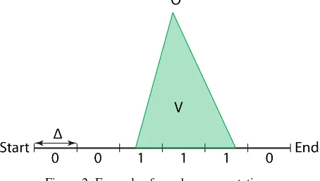
With the edges of the room subdivided into smaller segments, it becomes easy to define the discretized visibility polygon from a view pointOiby using boolean notations, as depicted in Fig. 2.
In practice the visibility edges do not perfectly coincide with the small segments boundaries and results in partially covered seg-ments. In this paper, these partially covered segments are consid-ered as visible.
Figure 2: Example of an edge segmentation.
The definition of the interval step∆will influence the number of segmentskand therefore the precision of the visibility coverage. Too large segments will result in less precise approximations of coverage, but with faster processing due to a low number of seg-ments. On the contrary, a fine segmentation enables to precisely define the boundaries of the visibility coverage at the expenses of longer processing time.
For then possible view pointsOi, i = 1...n, then visibility
polygonsVi, i= 1...nare computed following the
implementa-tion of Obermeyer and Contributors (2008). Each visibility poly-gon is discretized and snapped to the smaller edge segments of the room. The Boolean coverage information per view point is
then used in a Greedy algorithm to determine a minimum num-ber of view points necessary to cover all the edges of the room. At each step, this algorithm chooses the view point from which the largest number of segments is covered. The Greedy algorithm produces a good solution, often near the optimal solution, with a faster computation time (Slavk, 1996).
2.3 Incidence angle and Range constraint
The Terrestrial Laser Scanner measures distances to surfaces by emitting laser beams, either by continuous modulated signals or single pulses. In both cases, this technology has limitations in the range of measurements, both as a minimum distancedmin
and maximum distancedmaxthat can be measured to an object
surface. The manufacturer provides the range limitations specific to each laser scanner type.
Incorporating the range limitations in the determination of the visibility polygon provides a realistic representation of the ac-tual measurements capacity of the scanner (Gonzalez-Banos and Latombe, 2001). Moreover, Soudarissanane et al. (2011) previ-ously showed that the measurement quality deteriorates with bad scanning geometry, i.e. with increasing ranges and increasing in-cidence angles to the object surface. The inin-cidence angleαis defined as the angle between the laser beam and the normal of the surface. It is shown that increasing incidence angles result in deteriorated signal to noise ratio due to elongated footprints on the surface. Longer ranges result in wider footprints, which are more difficult to detect due to a decrease of signal strength. High incidence angles and longer ranges to the surface therefore result in less precise measurements. Modeling the scanning geometry effects enable to set incidence angles and range constraints to en-sure good quality scans.
3 SIMULATIONS OF MEASUREMENT SET-UP
To illustrate the method, two simulated case studies are presented. In both cases, a buffer ofdmin= 1m is applied around all edges
of the room to prevent positions too close to the surfaces. The interval step used for the segmentation of the edges is∆ = 0.05 m. These test cases are assuming that the scans will be acquired from a mid-range phase based terrestrial scanner, which often has a maximum range limitation ofdmax = 80m. From the study
of Soudarissanane et al. (2011), the maximum incidence angle on surfaces is set toαmax= 70◦.
The first scene is a simple squared room of400×400m, as de-picted in Fig. 3. The room is sampled with361possible view points spaced every20m on a regular Cartesian grid. This sim-ple test case is chosen to illustrate the impact of the scanning geometry constraints on the definition of the optimal view points locations.
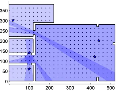
The second scene is a more complex room of520×380m, with multiple rooms and occlusions on walls, as depicted in Fig. 4. 356possible view points are chosen on a regular Cartesian grid. The effects of occlusions is demonstrated in this test case.
4 RESULTS AND DISCUSSIONS
areas in the polygon depending on the view point. As depicted in Fig. 4(a), multiple view points are required to obtain a complete coverage of the scene. In this case, five view points placed in the different opened rooms cover all the edges of the scene.
Applying the incidence angle constraint on the visibility poly-gons of a view point reduces the field of view of the scanner with respect to the surface orientations. As shown in Fig. 3(b), the simple room can still be fully visible with one view point, under the incidence angle constraint ofαmax = 70◦. This constraint
does not change the number of view point, it however provides a better position of the scanner from which incidence angles on surfaces are tolerable. As the complex room contains more edges with different orientations, the number of view points required to cover all the edges with an incidence angle smaller thanαmax
doubles to ten view points, as seen in Fig. 4(b).
The range constraints ofdmin= 1m anddmax= 80m enforce
a realistic representation of the measurements capabilities of a terrestrial laser scanner. The coverage of all edges of large rooms under range constraints results in the increase of the number of view points necessary to cover the scene. In the simple room case, twelve view points are needed, as shown in Fig. 3(c). As opposed to the visibility coverage without any constraints, many view points are required to cover a complete single edge of a scene. Fig. 4(c) shows that the complex room is covered by seventeen view points, which is a similar number as the ones re-quired under incidence angle constraint. This small difference is explained by the smaller ranges of the small opened rooms, which do not require more view points to fulfill the range constraints.
By incorporating both the maximum incidence angleαmaxand
the range constraintsdminand dmax, the optimal view points
necessary to cover a large room can be defined. These optimal view points ensure low incidence angle on surface and measured ranges to the surfaces that are within the specifications of the in-strument. The effects of bad scanning geometry are avoided, re-sulting in more reliable point clouds. As depicted in Fig. 3(d), fif-teen view points are necessary to cover the simple squared room. Nineteen view points are required to cover the complex room un-der the range and incidence angle constraints, as seen in Fig. 4(d).
5 CONCLUSIONS AND FUTURE WORK
An original method is presented in this paper to determine opti-mal view points in a scene based on terrestrial laser scanner ca-pabilities. It is shown that by considering the scanning geometry influences in a survey planning, the positions of the view points can be on forehand localized to capture scans of the surroundings with good quality.
The influence of an incidence angle constraint and of a range lim-itation is shown on two simulated rooms. The presented work uses a Cartesian griding of the room to determine possible view point location. An adaptive grid to the level of detail required per surface would improve the determination of the best view points. Moreover, a finer grid would avoid view points positions too close to each other, however it will be at the expenses of longer process-ing times.
The presented method handles the incidence constraint and the range constraints as two uncorrelated factors. However, in prac-tices these constraints are closely related. A combined constraint will provide a visibility from a view point that is more realistic.
Currently, the presented method uses a 2D discretized map of the scene at the height of the laser scanner. A possible extension of
this method would be to consider the 3D room and define the 3D visibility from a view point. The integration of several scan-ner height would improve the determination of the optimal view points.
Finally, in this paper we used a Greedy approach to select the best view points necessary to cover the scene. A better optimization algorithm would provide more optimal view points and better dis-tributed in the scene.
References
Besl, P. J. and McKay, N. D., 1992. A method for registration of 3-d shapes. IEEE Trans. Pattern Anal. Mach. Intell. 14(2), pp. 239–256.
Borah, D. K. and Voelz, D. G., 2007. Estimation of Laser beam pointing parameters in the presence of atmospheric turbulence. Applied Optics 46(23), pp. 6010–6018.
Bucksch, A., Lindenbergh, R. and van Ree, J., 2007. Error bud-get of Terrestrial Laser Scanning: Influence of the intensity remission on the scan quality. 1(Part 2), pp. 113–122.
Chvatal, V., 1975. A combinatorial theorem in plane geometry. Journal of Combinatorial Theory 18(1), pp. 39–41.
Chvatal, V., 1979. A greedy heuristic for the set-covering prob-lem. Mathematics of Operations Research 4(3), pp. 233–235.
de Berg, M., Cheong, O., van Kreveld, M. and Overmars, M., 2008. Computational Geometry: Algorithms and Applica-tions. Vol. 3rd rev, Springer-Verlag.
Dorninger, P., Nothegger, C., Pfeifer, N. and Molnar, G., 2008. On-the-job detection and correction of systematic cyclic dis-tance measurement errors of terrestrial laser scanners. Journal of Applied Geodesy 2(4), pp. 191–204.
Erdem, U. M. and Sclaroff, S., 2006. Automated camera layout to satisfy task-specific and floor plan-specific coverage require-ments. Computer Vision and Image Understanding 103(3), pp. 156–169.
Faro, 2010. Laser Scanner Photon 120. http://www.faro.com/ (Accessed 10 January, 2011).
Gonzalez-Banos, H. and Latombe, J.-C., 2001. A randomized art-gallery algorithm for sensor placement. (Part 1), pp. 232– 240.
Gorte, B., Khoshelham, K. and Verbree, E., n.d. Indoor naviga-tion by using segmentanaviga-tion of range images obtained by Laser Scanners.
Gruen, A. and Akca, D., 2005. Least squares 3D surface and curve matching. ISPRS Journal of Photogrammetry and Re-mote Sensing 59(3), pp. 151–174.
Hejbudzka, K., Lindenbergh, R., Soudarissanane, S. and Humme, A., 2010. Influence of atmospheric conditions on the range distance and number of returned points in leica scanstation 2 point clouds. XXXVIII(Part 5), pp. 282–287.
(a) In this case, only one view point is needed. Any of the possible
361view points fulfill the visibility constraint. The visibility polygon
is represented as the blue area.
(b) One view point is required to cover all the edges under incidence angles constraints. Multiple view points can fulfill the visibility under incidence angle constraints. The visibility polygon is represented as the red area.
(c) At least twelve view points are required to cover all the edges under range constraints. The visibility polygons are represented as the green areas.
(d) At least fifteen view points are required to cover all the edges un-der range and incidence angles constraints. The visibility polygons are represented as the gray areas.
Figure 3: Visibility coverage of simple room.361view points are used in the scene, depicted as black dots. Possible view points that fulfill the visibility constraints are depicted as stars, with their visibility coverage area. The darker the visibility area, the more view points coverage.
Kaasalainen, S., Krooks, A., Kukko, A. and Kaartinen, H., 2009. Radiometric calibration of terrestrial laser scanners with exter-nal reference targets. Remote Sensing 1(3), pp. 144–158.
Karp, R. M., 2010. Reducibility Among Combinatorial Prob-lems. Springer Berlin Heidelberg, pp. 219–241.
Kersten, T. P., Mechelke, K., Sterberg, H. and Acevedo Pardo, C., 2004. Terrestrial Laserscanning System Mensi GS100/GS200 - Accuracy tests, experiences and projects at the Hamburg Uni-versity of Applied Sciences. XXXIV(Part 5/W16), pp. 8.
Khoshelham, K. and Gorte, B., 2009. Registering point clouds of polyhedral buildings to 2d maps.
Landa, Y., Tsai, R. and Cheng, L.-T., 2006. Visibility of point clouds and mapping of unknown environments. 1(Part 1), pp. 1014–1025.
Leica, 2010. Laser Scanner HDS6000. http://www.leica-geosystems.com/ (Accessed 10 January, 2010).
Lichti, D. D., 2007. Error modelling, calibration and analysis of an AM CW Terrestrial Laser Scanner system. ISPRS Journal of Photogrammetry and Remote Sensing 61(5), pp. 307–324.
Obermeyer, K. J. and Contributors, 2008. The VisiLibity library. http://www.VisiLibity.org R-1.
Obermeyer, K. J., Ganguli, A. and Bullo, F., 2010. Multi-agent deployment for visibility coverage in polygonal environments with holes. International Journal on Robust and Nonlinear Control 00, pp. 1–31.
O’Rourke, J., 1987. Art Gallery Theorems and Algorithms. Ox-ford University Press, UK.
Reed, M. K. and Allen, P. K., 1999. 3-d modeling from range imagery: An incremental method with a planning component. Image and Vision Computing 17(2), pp. 99–111.
(a) At least five view points are required to cover all the edges. The visibility polygons are represented as the blue areas.
(b) At least ten view points are required to cover all the edges under incidence angles constraints.The visibility polygons are represented as the red areas.
(c) At least seventeen view points are required to cover all the edges under range constraints. The visibility polygons are represented as the green areas.
(d) At least nineteen view points are required to cover all the edges under range and incidence angles constraints. The visibility polygons are represented as the gray areas.
Figure 4: Visibility coverage of a complex room.356view points are used in the scene, depicted as black dots. Possible locations of the scanner that fulfil the visibility constraints are depicted as stars, with their visibility coverage area. The darker the visibility area, the more view points coverage.
Slavk, P., 1996. A tight analysis of the greedy algorithm for set cover. 1(Part 1), pp. 435–441.
Soudarissanane, S., Lindenbergh, R., Menenti, M. and Teunis-sen, P., 2011. Scanning geometry: Influencing factor on the quality of terrestrial laser scanning points. ISPRS Journal of Photogrammetry and Remote Sensing.
Tomas, A. P., Bajuelos, A. L. and Marques, F., 2006. On visi-bility problems in the plane – solving minimum vertex guard problems by successive approximations. 1(Part 1), pp. 1–12.
Voisin, S., Foufou, S., Truchetet, F., Page, D. and Abidi, M., 2007. Study of ambient light influence for three-dimensional scanners based on structured light. Optical Engineering 46(3), pp. 030502–1 030502–3.
Vosselman, G. and Maas, H. G., 2010. Airborne and Terres-trial Laser Scanning. Whittles Publishing, Dunbeath, Scotland, UK.
Vosselman, G., Gorte, B. G. H., Sithole, G. and Rabbani, T., 2004. Recognising structure in Laser scanner point clouds. International Journal of Photogrammetry, Remote Sensing and