A METHOD FOR SIMULTANEOUS AERIAL AND TERRESTRIAL GEODATA
ACQUISITION FOR CORRIDOR MAPPING
P. Molina a , M. Blázqueza, J. Sastre a , I. Colomina a
a GeoNumerics, Castellefels, Spain – (pere.molina, marta.blazquez, jaume.sastre, ismael.colomina)@geonumerics.com
ICWG I/Vb
KEY WORDS: Unmanned Aerial Vehicle (UAV), geomatics, corridor mapping, Terrestrial Mobile Mapping (TMM), integrated sensor orientation (ISO), Galileo E5 AltBOC, EGNOS.
ABSTRACT:
In this paper, we present mapKITE, a new mobile, simultaneous terrestrial and aerial, geodata collection and post-processing method. On one side, the method combines a terrestrial mobile mapping system (TMMS) with an unmanned aerial mapping one, both equipped with remote sensing payloads (at least, a nadir-looking visible-band camera in the UA) by means of which aerial and terrestrial geodata are acquired simultaneously. This tandem geodata acquisition system is based on a terrestrial vehicle (TV) and on an unmanned aircraft (UA) linked by a 'virtual tether', that is, a mechanism based on the real-time supply of UA waypoints by the TV. By means of the TV-to-UA tether, the UA follows the TV keeping a specific relative TV-to-UA spatial configuration enabling the simultaneous operation of both systems to obtain highly redundant and complementary geodata.
On the other side, mapKITE presents a novel concept for geodata post-processing favoured by the rich geometrical aspects derived from the mapKITE tandem simultaneous operation. The approach followed for sensor orientation and calibration of the aerial images captured by the UA inherits the principles of Integrated Sensor Orientation (ISO) and adds the pointing-and-scaling photogrammetric measurement of a distinctive element observed in every UA image, which is a coded target mounted on the roof of the TV. By means of the TV navigation system, the orientation of the TV coded target is performed and used in the post-processing UA image orientation approach as a Kinematic Ground Control Point (KGCP). The geometric strength of a mapKITE ISO network is therefore high as it counts with the traditional tie point image measurements, static ground control points, kinematic aerial control and the new point-and-scale measurements of the KGCPs. With such a geometry, reliable system and sensor orientation and calibration and eventual further reduction of the number of traditional ground control points is feasible.
The different technical concepts, challenges and breakthroughs behind mapKITE are presented in this paper, such as the TV-to-UA virtual tether and the use of KGCP measurements for UA sensor orientation. In addition, the use in mapKITE of new European GNSS signals such as the Galileo E5 AltBOC is discussed. Because of the critical role of GNSS technologies and the potential impact on the corridor mapping market, the European Commission and the European GNSS Agency, in the frame of the European Union Framework Programme for Research and Innovation “Horizon 2020,” have recently awarded the “mapKITE” project to an international consortium of organizations coordinated by GeoNumerics S.L.
1. A NEW GEODATA ACQUISITION AND MAPPING PARADIGM
Geoinformation is a pillar infrastructure of modern society as many other infrastructures and services depend on it. Examples are found in application fields like Location Based Services (LBS), smart cities, safety and security, disaster management, land management and survey, energy or climate change monitoring. Geoinformation, understood as the modern 3D maps and beyond, is indeed expensive to create and expensive to update. Local and national agencies and departments in charge of geoinformation have to cope with a growing professional and popular demand for high-resolution, up-to-date geoinformation supported by ever-decreasing budgets.
Unmanned Aerial Systems (UAS) have simply revolutionized the mapping perspective. The blossom of small, low-cost and easy-to-operate aerial robots is now a consolidated evidence as
per the mass-market adoption, very well exemplified by the case of the Parrot's AR.drone, but also featuring a remarkable penetration in professional markets. Sensefly's Swinglet or eBee, Trimble's UX-5 or Ascending Technologies' Falcon-8 are now part of surveyor must-have tools to produce high-resolution orthophotography and 3D models at a competitive price and ease of operation (Colomina and Molina, 2014). Regulatory –not technical– barriers have restricted operations to few-hundred-meter-radius non-populated areas, which have leveraged the use of UAS in mining and archaeological site survey as well as agriculture, but have built an operational fence around infrastructure or urban mapping.
been measured by TMMS with different sensor technology, ranging from visible- or thermal-band cameras to LiDAR, and systems have become a commercial standard of big players in the geomatics community, such as Optech, Leica, TopCon, Trimble, etc. Last but not least, the deployment of Google's StreetView service has brought TMMS-based geoinformation
at the street level worldwide fostering its global acceptance and adoption.
MapKITE is therefore reaping the benefits of these two, well-established mapping paradigms which already exist as commercial stand-alone solutions, and aims at exploiting the added value of its combination. On one hand, the mapKITE concept eliminates the need for separate terrestrial and aerial surveys and lowers costs by using UAS (instead of traditional manned flights for aerial mapping) yielding at least comparable results (Colomina and Molina, 2014). On the other side, UAS and TMMS -even Terrestrial Laser Scanner (TLS)- present a natural complementarity (Gruen et al., 2013), (Faust, 2014). While TMMS and TLS is suited for bottom-level mapping (ground, façades, under-the-canopy), UAS complements it with top-level mapping (roofs, over-the-canopy, beyond TMMS measurement range). Also at the navigation level, the GNSS multipath and/or occlusion problems, typical in TMMS environments, are not experienced by UAS. We therefore believe that combining UAS and TMMS/TLS might even become one of those historical hybridizations, just as INS/GPS was at its time.
From an application standpoint, mapKITE targets naturally at corridor mapping of roadways, railways and/or waterways, and is naturally extended to pipeline or powerline monitoring. The line-of-sight keeping nature of mapKITE between a mobile Ground Control Station (GCS) and the UA drops the need of operating at a maximum radius from a static GCS set-up and enables continuous operation along linear long corridors. The UA imagery covers the central part of the corridor plus its surroundings which might not been observed from the TV point of view e.g. roads surrounded by trees or small hills. This makes apparent the aforementioned UA and TV complementarity in mapKITE, at least from the mapping perspective.
Regulations are also a driving factor of mapKITE. Besides the open regulatory aspects in constant evolution inherited by its UAS nature (Colomina and Molina, 2014), there are some aspects, specific to the proposed system, to be dealt with. One example is the moving nature of the GCS, which apparently has been identified by the Federal Aviation Administration (FAA) as a conflictive operational aspect but still open for discussion (FAA, 2015) and that has already been responded by AUVSI, the Association for Unmanned Vehicle Systems International (AUVSI, 2015). Yet, the most challenging scenario in terms of regulations for mapKITE is by far the operation in urban environments (towns, cities, populated areas). Although regulatory bodies will have to face such scenarios as pushed by big players interested in commercial UAS applications (Amazon, Google, Facebook, etc.), it is a medium- or long-term goal of mapKITE and the focus is kept, as mentioned, in corridor mapping of inhabited areas (roads, railways, waterways pipelines, powerlines, etc.)
It is noteworthy that mapKITE does not consider a loose combination of the UA and TV systems in which just the two systems operate together. Oppositely, a tight integration of a UAS and a TMMS is envisioned by:
an operation procedure to collect simultaneously aerial and terrestrial geodata,
a post-processing approach to fully exploit the geometric strength and redundancy of the measurement network created in a mapKITE mission.
Therefore, mapKITE presents a novel paradigm for geodata acquisition and mapping based on a highly integrated and redundant configuration of a UAS and MMS. The novelty of the approach is certified by the grant of a patent to GeoNumerics (Spanish patent 201231200) and further PCT applications have been filed to cover Europe, United States and Brazil.
Besides being a new mapping concept and a GeoNumerics invention, the third cornerstone of the mapKITE essence is the research project currently being funded by the European Commission (EC) and the European GNSS Agency (GSA), in the frame of the Horizon 2020 R&D framework. An international consortium of organizations coordinated by GeoNumerics is now developing a pre-commercial version of the system, started in March, 2015, and which will be ready for beginning of 2017. The consortium is formed by TopScan GmbH, Germany; GRID-IT GmbH, Austria; DEIMOS Engenharia, Portugal; UAVision, Portugal; École Polytechnique Fédéral de Lausanne, Switzerland; CATUAV, Spain; Altais S.L., Spain; Engemap, Brasil; Universidade Estadual Paulista, Brazil.
Hereafter, sections 1.1 to 1.5 describe the various system technical components and concepts behind mapKITE, and provide details about its implementation within the current H2020 project developments.
1.1 Unmanned Aircraft and Terrestrial Vehicle
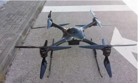
The core components in mapKITE are, indeed, the UA and the TV as principal carriers of the remote-sensing instruments to acquire geodata. In the H2020 project, the aerial component is based on the UX-SPYRO-8 platform by UAVision (PT), shown in figure 1. It is a carbon-fiber octocopter with electrical ultra-low noise propellers featuring a cross-length of 1131 mm (w/o propellers) and a height of 540 mm. The UX-SPYRO-8 can operate at a maximum speed 65 km/h carrying a maximum of 7 kg payload. The autopilot hardware is fully designed by UAVision and is compatible with Pixhawk PX4 and Ardupilot APM firmwares.
The UA remote sensing payload in mapKITE admits a priori several configurations, just as in conventional UAS missions (visible-band, infra-red, thermal, etc.) For the purpose of corridor mapping, a Sony NEX-7 camera has been selected in the H2020 project including a 20 mm camera constant lens. As an illustration, such a camera-lens configuration delivers an image forward overlap of about 79% when flying at 100 m above terrain at 60 km/h, and shooting at one frame-per-second, which is in line with standard photogrammetric requirements for corridor mapping (80%).
Figure 2. Lynx M1 integrated by TopScan (DE)
The terrestrial component in mapKITE might also been scaled according to the restrictions imposed by the mission scenario land type. Land vehicles (cars, vans) are suitable carriers of mobile mapping systems for corridor mapping. In line with this fact, the TV in the H2020 project is provided by TopScan GmbH (depicted in Figure 2) consisting on a van equipped with a mobile mapping system, the Lynx M1 from Teledyne Optech Inc. This system is used in a configuration of two LiDAR systems and two optical 5-MPx cameras. Each LiDAR system provides measurement rate up to 500 kHz and is able to receive up to 4 echos per pulse. The measurement range is around 200 m with a precision of 0.5 cm (1 ).
Besides a MMS, the TV is also the host of a portable GCS for UA command-and-control and telemetry monitoring. The mapKITE operator controls the UA mission from the TV on-the-go and is able to take manual control of the UA using First-Person View (FPV) remote control. For the H2020 project, an in-house UAVision GCS development is used, duly extended to include the virtual tether mechanism.
1.2 Fiducial target on the TV roof
The TV incorporates a fundamental feature in mapKITE. A fiducial optical target is mounted on the TV roof to be observed from an aerial point of view, in particular, from the UA camera. As developed later in this paper, the goal of such a target is twofold: firstly and mainly, to provide photogrammetric measurements of its centre to be used for post-processing UA image orientation and, secondly, to perform continuous tracking of the vehicle as an additional measure of robustness to the main guidance system (the virtual TV-to-UA tether). For the H2020 project, the particular selection for this element is the Smile Target (Cucci et al., 2015), a circular-shaped coded target.
1.3 UA and TV navigation and orientation systems
The on-board UA autopilot is responsible for UA navigation – that is, real-time orientation– and also performs UA guidance to manage several mission plans, which can be pre-defined
depending on the mission to be executed or dynamic if based on the virtual tether waypoints. In mapKITE, additional navigation sensors are integrated on the UA payload to complement the Integrated Sensor Orientation (ISO) post-processing approach (further explained in section 2). More specifically, geodetic-grade multi-frequency GNSS receivers are aimed to provide good quality aerial control and a precise time reference for the UA images enabling synchronization with TV measurements. For the H2020 project, a MEMS-INS/GNSS ensemble is mounted on the UA payload as described in (Rehak et al., 2013).
At the ground level, an INS/GNSS system featuring a higher grade IMU is available from the TMMS. On one side, navigation sensor measurements are post-processed to perform accurate and precise orientation of the TV sensors and, therefore, deliver geo-referenced point cloud and/or imagery. Considering due lever-arms and boresights, orientation is provided to the roof target which is a necessary step for its use as KGCPs for sensor orientation, as explained in chapter 2. On the other side, a real-time full navigation solution (time, position, velocity and attitude, tPVA) is provided by the TV navigation system, and input into the GCS to be used as the primary source for the UA waypoints provided by the virtual TV-to-UA tether. For the H2020 project, the TopScan TMMS system features a POS-LV 420 orientation system (Applanix, 2015), based on a tactical-grade IMU and geodetic-grade dual-frequency GNSS receiver.
1.4 TV-based UA guidance: the kite's virtual tether
The real-time output from the TV navigation received by the GCS is processed by smoothing algorithms to filter noise in position estimation. In addition, statistical analysis is carried out to identify and reject potential GNSS outliers due to interference, multipath or signal attenuation. Then, in order to build a UA waypoint, a mission-dependant shift is applied to the position component (mainly but not exclusively, a height positive shift) and a heading angle parameter is also added (note that TV pitch and roll values are not considered for UA guidance, and heading of the UA might differ from the TV's).
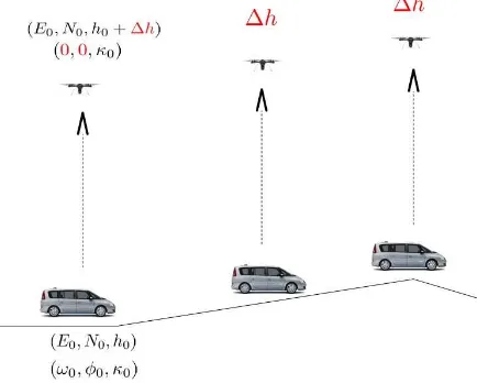
Each waypoint is then included i.e. enqueued in the route of the mission plan to be executed. Special waypoints are also defined to carry pre-defined turns, short translations and ascents/descents for camera calibration purposes. Figure 3 depicts the dynamics of a mapKITE mission driven by the TV-to-UA tether.
1.5 The role of European GNSS: EGNOS and Galileo E5 AltBOC
The mapKITE mission mapping performance and operational safety heavily relies on GNSS. From one side, UA navigation shall be accurate, safe and still hold valid under the UAS paradigm (low-cost, easy-to-deploy). These pre-conditions exclude single-frequency standalone real-time GPS solutions due to its lack of accuracy, and also real-time kinematic (RTK) based-solutions, usually expensive and requiring static ground set-ups. In turn, these UAS pre-conditions are suited for the use of Satellite-based Augmentation Systems (SBAS). The H2020 project focuses on the European EGNOS which, as pointed out in previous experiences, is an enabler of navigation accuracy delivering an actual performance of μH= 0.53 m, μV= 0.97 m 1σ (Ventura et al., 2006), and safety for UAS due to its integrity functionality (Molina et al., 2012). Current SBAS systems cover now the main populated areas in the world, and commercial systems such as Omnistar provide full world-wide coverage.
On the other hand, the quality of the TV navigation solution has a direct impact on the UA behaviour as per the virtual tether mechanism. Therefore, large errors in TV navigation may imply a degradation of the mapping mission performance (loss of image overlap, variable footprint), augmenting vehicle stress (unwanted slaloms) even compromising the mission safety. To this respect, the H2020 mapKITE project investigates about the tether robustness by adding the new Galileo E5 AltBOC signals (Lestarquit et al., 2008). The particular AltBOC modulation presents a high code range precision down to 2 cm in open-air conditions, and up to 8 cm in degraded environments (Colomina et al., 2012a). In addition, this modulation features advanced multipath resiliency properties, as shown in (Colomina et al., 2012a), by which beyond-30-meter multipath delay has null impact on code delay error, and below-30-meter multipath delay has a maximum impact of one meter in code delay. At this point in time, the E5 AltBOC measurements will be added in the computation of the UA waypoints to benefit from these multipath resiliency properties. On the long term, TV and UA navigation will primarily depend on the E5 AltBOC code range measurements.
In addition to UA and TV navigation, the new E5 AltBOC measurements will play a role on mapping. Galileo ranges will be part of a multi-frequency, multi-constellation (together with GPS) post-processing approach to generate the aerial control for UA sensor orientation. By doing so, the accuracy potential of Galileo code-only or code-plus-phase measurements will be leveraged. The H2020 project will put in place two replicas (aerial and ground) of an experimental Galileo E1/E5 receiver developed by DEIMOS Engenheria.
Although the primary interest is to fight outliers at the ground level, a second mechanism is conceived to enhance robustness
at the air level, based on a tracking camera integrated on the UA payload to perform a continuous, real-time tracking of the fiducial target on the TV roof and estimation of the relative TV-to-UA orientation, which can then be fed back to the autopilot.
By doing so, GNSS outliers related to the TV navigation solution become apparent as compared to this camera-based solution. In the H2020 project, a Ximea MQ042MG 4M camera will be used for such purpose, as described in (Cucci et al., 2015).
2. APPROACH TO SENSOR ORIENTATION IN MAPKITE
As previously mentioned, the task of sensor orientation for the TV and UA sensors inherits the principles of ISO with some additional features. Precisely, the simultaneity in geodata acquisition in mapKITE enables novel approaches for simultaneous sensor orientation of both platforms, in addition to the independent, standard approaches for each individual platforms. This reveals the mapKITE system as a truly complementary system, also at the processing level, by which the errors of the ground component might be observed and corrected by means of the aerial component, and viceversa.
Hereafter, section 2.1 describes the mapKITE mission for geodata acquisition, section 2.2 introduces the measurements produced by a mapKITE system, and section 2.3 introduces the proposed processing approaches of these measurements.
2.1 Mission design and execution in mapKITE
A typical mapKITE mission entails a set of manoeuvres designed to ensure mission safety and, at the same time, maximize the quality of the observables for posterior sensor orientation and minimize the cost of a mapping mission.
Starting from a base point, the mapKITE system is turned on and activates the calibration phase. In this phase, the UA performs turns and short translations while ascending up to operational altitude, keeping the TV target in view to collect data for a posteriori camera calibration. Once this phase is completed, the TV drives a predefined route and the UA follows it, according to the virtual tether and according to pre-defined “geo-fences” related to the mission route and to the maximum allowed TV-to-UA distances.
While operating at a similar speed to keep TV-to-UA line-of-sight, the mapKITE operator controls the mission from the TV with the ability to take first-person view manual control of the UA at any time, control the UA telemetry and/or manipulate mission parameters (TV-to-UA distance, mission plan modality, etc.) Geodata are acquired according to particular mapping requirements (image footprint size, ground sampling distance, etc.) along a corridor between a first base point and a second base point, where the TV stops and the UA descends again performing calibration manoeuvres. Both initial and end stops are worth to capture static navigation data for state initialization in post-processing. This procedure is repeated until mission is completed. The corridor can be eventually land surveyed, before or after the mission, to provide ground control points.
measurements and post-processing approaches followed in mapKITE are presented hereafter.
2.2 Measurements for sensor orientation and calibration
Two types of measurements are generated on or related to the UA, the navigation ones and the photogrammetric ones. On one side, MEMS-IMU inertial measurements together with the code and phase GNSS measurements (including Galileo E5 AltBOC) are available to be used for aerial control. On the other side, traditional and new photogrammetric measurements are performed on UA images. Firstly, tie points are automatically extracted and measured on overlapping images. The challenges of tie point measurement on aerial images of corridors are well known (ill-textured areas, moving vehicles among other) and not different from conventional low-altitude aerial photography.
In addition to these, mapKITE introduces the photogrammetric measurements of a point and its scale for elements with known metrical properties in the object space. In other words the measurement will consist on a treble , where are the coordinates of a distinguished point, and is the scale of that point on a given image. This type of measurement (in red) is used in the equation model (1), the vectorial form of the collinearity equations:
(1)
where L is a local cartesian east-north-up reference frame in the object space; c is the forward-left-up sensor frame; are the Euler angles corresponding to the rotation of the c frame to the L frame; is the position of the camera projection center; are the coordinates of the measured point in the object space; and f is the focal length of the camera.
On the TV side, a similar set of measurements is obtained, that is, INS/GNSS measurements, yet featuring a higher grade IMU than the UA one. Note that the TV INS/GNSS trajectory provides orientation to the TV fiducial target. Therefore, accompanying the point-and-scale observation equation of the fiducial target in the UA images (equation 1), an additional observation equation for using a position measurement derived from the TV INS/GNSS is also used. This is also valid for additional static GCP fiducial targets.
Finally, we note the utmost importance of an accurate time synchronization of all measurements, the TV and the UA ones, in a common time reference frame i.e. GNSS, which is accomplished by time-tagging camera images using the return signal of the camera flash. Results for a similar camera showed a synchronization precision better than 2 ms (Rehak et al., 2013).
2.3 Post-processing for sensor orientation and calibration
The following sequence of actions conform the mapKITE post-processing approach:
• Compute TV and UA tPVA trajectories independently.
• Extract tPA aerial control for the UA images (from the UA trajectory) and ground control for the KGCPs (from the TV trajectory).
• Integrate the tPA aerial control with the photogrammetric observations (tie points, static and kinematic GCPs) in order to compute the orientation and calibration parameters of the UA images. (ISO step)
In relation to UA and TV INS/GNSS processing, two different strategies are followed. UA INS/GNSS processing strongly relies on the high quality of the GNSS measurements (code and phase multi-frequency and multi-constellation measurements) in contrast to the MEMS-IMU measurements. By doing so, a tPVA trajectory is obtained consisting on high-quality position and moderate-quality attitude estimation. The attitude estimation is still useful for exterior orientation initialization in the ISO approach and for geometrical consistency check of the tie point measurement quality. Oppositely, the TV INS/GNSS trajectory is obtained by more heavily relying on the higher-grade INS to mitigate the effect of contaminated GNSS due to multipath, attenuation or occlusion effects, common in TMMS.
Both UA and TV INS/GNSS trajectories are typically obtained under the state-space approach, that is, using sequential least-squares techniques (Kalman filtering and smoothing). Yet, the dynamic network approach (Colomina and Blázquez, 2004) enables also INS/GNSS trajectory determination by fully connecting the navigation parameters regardless of time. Once these trajectories are obtained, they are used as observations together with the photogrammetric measurements in a global non-linear least squares adjustment (Colomina et al., 2012b). Furthermore, we will use INS/GNSS trajectories as relative aerial and ground control (Blázquez and Colomina, 2012) as this is beneficial in two ways: firstly, it eliminates the need of IMU-to-camera boresight calculation, and secondly, relative control measurements are more robust to GNSS constellation cycle slips.
3. CONCLUSIONS AND FUTHER RESEARCH
This paper presents the main ideas behind mapKITE, a new concept and paradigm for simultaneous aerial and terrestrial geodata acquisition, based on the integration of an unmanned aircraft and a terrestrial vehicle, both carrying remote sensing payloads. By means of a virtual tether mechanism, real-time waypoints are supplied from the TV to the UA to materialize a tandem system for corridor mapping applications.
As a complement to the system and its operation, mapKITE includes a novel sensor orientation approach derived from the strength of its measurement network. Based on integrated sensor orientation with traditional tie point measurements, ground and aerial control, it includes the kinematic ground control points (a fiducial target installed on the TV and observed by the UA) and the point-and-scale measurements to be used in the vectorial form of the collinearity equations.
As for mapKITE sensor orientation approach, research will focus on the analysis of the contributions of the point-and-scale measurements as well as the KGCPs compared to conventional corridor mapping configurations with many more static GCPs and no KGCPs. Additionally, in order to fully exploit the geometric strength inherent to the mapKITE configuration, the aforementioned dynamic network approach for sensor orientation will be used to proceed with a simultaneous, connected determination of the UA and TV orientation parameters. According to expectations, the TV navigation errors shall be removed by the UA navigation when more favourable UA conditions hold, and viceversa.
ACKNOWLEDGEMENTS
MapKITE is an invention of GeoNumerics. The research and development for the practical materialization of the concept is currently beingfunded by the European Community Horizon 2020 Programme under grant agreement no. 641518 (project mapKITE, www.mapkite.com) managed by the European GNSS Agency (GSA).
The parallel research mentioned in this paper regarding the concept of dynamic networks has been financially supported by the project DINA (Ref. SPTQ1201X005688XV0, Subprogama Torres y Quevedo, Spain)
MapKITE is protected by the Spanish patent 201231200. International patents have been filed.
REFERENCES
AUVSI, 2015. Association for Unmanned Vehicle Systems International (AUVSI) response to the FAA’s Notice of Proposed Rulemaking for Small Unmanned Aircraft Systems (sUAS), Link: http://goo.gl/Ci3nQr, accessed on July, 5th
2015.
Blázquez, M., and Colomina, I., 2012. Relative INS/GNSS aerial control in integrated sensor orientation: models and performance. ISPRS Journal of Photogrammetry and Remote Sensing, volume 67 (2012), pages 120–133, ISSN 0924-2716.
Colomina, I. and Blázquez, M., 2004. A unified approach to static and dynamic modelling in photogrammetry and remote sensing. International Archives of Photogrammetry, Remote Sensing and Spatial Information Sciences, Vol. 35-B1, Comm. I, pp. 178-183.
Colomina, I., Miranda, C., Parés, M.E., Andreotti, M., Hill, C., Silva, P.F., Silva, J.S., Peres, T., Galera Monico, J.F., Camargo, P.O., Fernández, A., Palomo, J., Moreira, J., Strei, G., Granemann, E.Z., Aguilera, C., 2012. Galileo's surveying potential: E5 pseudorange accuracy. GPS World, Vol. 23, No. 3, March 2012, pp. 18-33.
Colomina, I., Blázquez, M., Navarro, J.A., and Sastre, J., 2012.
The need and keys for a new generation network adjustment software. International Archives of the Photogrammetry, Remote Sensing and Spatial Information Sciences, volume XXXIX-B1, pages 303-308.
Colomina, I., Molina, P., 2014. Unmanned aerial systems for photogrammetry and remote sensing: A review. ISPRS Journal of Photogrammetry and Remote Sensing, Volume 92, June 2014, Pages 79-97, ISSN 0924-2716.
Cucci, D., Constantin, D., Rehak, M., 2015. Smile targets in aerial photogrammetry. Proceedings of the International Micro Air Vehicle Conference and Competition 2015, Aachen, Germany, September 15-18, 2015.
Gruen, A., Huang, X., Qin, R., Tangwu, D., Fang, W., Boavida, J., Oliveira, A., 2013. Joint processing of UAV imagery and terrestrial mobile mapping system data for very high resolution city modelling. International Archives of the Photogrammetry, Remote Sensing and Spatial Information Sciences, Volume XL-1/W2, 2013 UAV-g2013, 4 – 6 September 2013, Rostock, Germany
FAA, 2015. Operation and Certification of Small Unmanned Aircraft Systems, Federal Aviation Administration (FAA), Billing Code 4910-13-P, Link: https://goo.gl/bSuF28, accessed on July, 5th 2015.
Faust, J., 2014. Rapid survey of open pit mines with terrestrial LiDAR and aerial triangulation. LiDAR magazine, Vol. 4, No. 1.
Lestarquit, L., Artaud, G., Issler, J.-L., 2008. AltBOC for Dummies or Everything You Always Wanted To Know About AltBOC, Proceedings of the 21st International Technical Meeting of the Satellite Division of The Institute of Navigation (ION GNSS 2008), Savannah, GA, September 2008, pp. 961-970.
Molina, P., Parés, M.E., Colomina, I., Vitoria, T., Silva, P.F., Skaloud, J., Kornus, W., Prades, R., Aguilera, C., 2012. Drones to the rescue! Unmanned aerial search missions based on thermal imaging and reliable navigation. Inside GNSS, Vol. 7, No. 4, July-August 2012, pp. 36-47.
Rehak, M., Mabillard, R., Skaloud, J., 2013. A micro-UAV with the capability of direct geo-referencing. International Archives of the Photogrammetry, Remote Sensing and Spatial Information Sciences, Volume XL-1/W2, 2013 UAV-g 2013, 4 – 6 September 2013, Rostock, Germany