3D POINT CLOUD MODEL COLORIZATION BY DENSE REGISTRATION OF DIGITAL
IMAGES
N. Crombez, G. Caron, E. Mouaddib
University of Picardie Jules Verne MIS Laboratory 33 rue Saint Leu 80039 AmiensCEDEX1
{nathan.crombez, guillaume.caron, mouaddib}@u-picardie.fr
Commission V, WG V/4
KEY WORDS:Point clouds, Virtual and Visual Servoing, Images Registration, Colorization
ABSTRACT:
Architectural heritage is a historic and artistic property which has to be protected, preserved, restored and must be shown to the public. Modern tools like 3D laser scanners are more and more used in heritage documentation. Most of the time, the 3D laser scanner is completed by a digital camera which is used to enrich the accurate geometric informations with the scanned objects colors. However, the photometric quality of the acquired point clouds is generally rather low because of several problems presented below.
We propose an accurate method for registering digital images acquired from any viewpoints on point clouds which is a crucial step for a good colorization by colors projection. We express this image-to-geometry registration as a pose estimation problem. The camera pose is computed using the entire images intensities under a photometric visual and virtual servoing (VVS) framework. The camera extrinsic and intrinsic parameters are automatically estimated. Because we estimates the intrinsic parameters we do not need any informations about the camera which took the used digital image. Finally, when the point cloud model and the digital image are correctly registered, we project the 3D model in the digital image frame and assign new colors to the visible points.
The performance of the approach is proven in simulation and real experiments on indoor and outdoor datasets of the cathedral of Amiens, which highlight the success of our method, leading to point clouds with better photometric quality and resolution.
1. INTRODUCTION
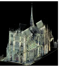
Cultural heritage contains important remnants of our past and has to be carefully safeguarded. That is why patrimony docu-mentation represents an important research issue. Cultural her-itage includes monuments, works of art and archaeological land-scapes. These sites are frequently faced with environmental con-ditions, human deterioration and can be victim of their age. The E-Cathedrale1research program was born in this context of cul-tural heritage preservation. It is dedicated to the digitization of the cathedral of Amiens, in France, to get a complete and pre-cise model never obtained. This cathedral reaches an internal height of 42.30 meters for 200,000 cubic meters interior volume. Among French cathedrals of which the construction is over, the one of Amiens is the tallest and has the greatest interior volume. The cathedral was built between 1220 and 1270 and has been listed as a UNESCO World Heritage Site since 1981.
Recent technological advances have enabled the development of tools and methods, like 3D laser scanners which allow to quickly and accurately scan the spatial structure of monuments. The scan result is a dense and panoramic 3D point cloud of the scene. The first three scanning campaigns of the cathedral have allowed to obtain billions of points (Fig. 1) with approximately 2 millime-ters sampling resolution on the details and less than 5 millimemillime-ters on the other parts. A digital camera is included into the laser scan-ner to assign color informations to each acquired 3D point. How-ever, the photometric quality of the acquired point clouds model is generally rather low because of several problems. First of all, the scanner camera has a low resolution compared to the 3D scan-ner acquisition itself, because of that a 3D point and its nearest neighbors are colorized with the same digital image pixel. This
1https://mis.u-picardie.fr/E-Cathedrale/
Figure 1: View of the Amiens cathedral point clouds model
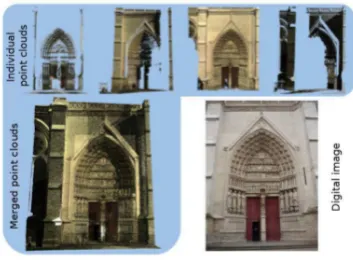
Figure 2: Color problems resulting of the point clouds merging and the scanner camera low quality
2. RELATED WORK
In recent years, the use of 3D technologies has become the major method to accurately measure architectural or historical objects because of their high performance. These measured ”objects” can be small as the Sidamara grave (Altuntas et al., 2007) and huge as a desert palace in Jordan (Al-kheder et al., 2009) or as the Todai-ji in Japan, the world biggest wooden edifice (Ikeuchi et al., 2007). In all cases, the aim is to obtain an accurate documentation with a high level of realism for protection, conservation and for possible future restoration or archaeologists studies. Several measurement acquisition methods exist: with terrestrial laser scanners (Had-dad, 2011), terrestrial or aerial photogrammetric methods or by close range photogrammetry (Moussa et al., 2012).
It seems interesting to use the laser scanner and the digital cam-era separately. Indeed, terrestrial laser scanner measurements can be combined with Close Range Photogrammetry method or with digital images to improve the texture quality and resolution with a photometric realism (Al-kheder et al., 2009) (Henry et al., 2012). These methods require the registration of the data sets which are collected by the laser scanner and the digital images acquired by the camera. This registration is a crucial step for a good coloriza-tion, this is why it has long been studied and many approaches has been proposed. These approaches have been categorized by M. Corsini and al. (Corsini et al., 2012).
The first category contains the simplest methods, when the two device poses are known relatively to each other. This method is used in (Abmayr et al., 2004) where 3D point clouds and 360 de-grees high resolution images are acquired from a same geograph-ical position. Therefore, transforming both coordinate systems into each-other is easily done. However, to cover a large environ-ment the scanner has to be placed far from the scene. The camera is far from the scene too, therefore the acquired digital images have a lack of visual details.
Registration can be also done using corresponding features from both data sets. These corresponding features can be points, lines or else. These can be manually chosen or automatically detected. In (Adan et al., 2012), points are manually chosen. Point clouds are used to generate ortho-images and corresponding points are manually selected in the virtual ortho-images and the digital one. A transformation matrix is computed using these sparse sets of corresponding points to register images and the 3D point cloud. Points can be automatically detected using SIFT, ASIFT or other point features extraction methods. In (Moussa et al., 2012), fea-tures are extracted using SIFT in the digital image and in a point-based environment model. In some cases (Alshawabkeh and Haala, 2004), manually or automatically selected, lines may be more ap-propriate given the straight geometry of the scanned environment. Laser scanners assign to the acquired points a reflectance value.
This reflectance is sometimes used to make the data of the two systems more similar (Mastin et al., 2009) and facilitate the fea-tures detection.
Registration can be done comparing 3D model shapes and objects contours detected in the digital image (Belkhouche et al., 2012). Some works are using several images to obtain a sparse 3D point cloud, for example by Structure from Motion (SfM). Then, this point cloud is registered with the 3D target model. This 3D/3D registration performed, the images used for the SfM can be aligned to the model and used to colorize it. However, these methods re-quire a large number of digital images.
Finally, other methods try to minimize mutual informations be-tween digital images and 3D model geometric features. Differ-ent features like normals, reflection, ambiDiffer-ent occlusions are com-pared in (Corsini et al., 2009). The results of their study show better image-to-geometry registrations using normals maps and a combination of normals and ambient occlusion.
The huge size of the cathedral leads us to use the automatic fea-tures extraction methods. The color problems presented above make difficult the features detection and registration. Thanks to a point clouds colors homogenization, we are able to automatically detect and match point features between a virtual image of the 3D scene and a digital one. A camera pose is computed using these sparse sets of 2D/3D corresponding points to register the digital image and the 3D point cloud model. However, these kind of registrations are not enough accurate, the digital and the virtual images are not correctly aligned. We propose to correct the ob-tained camera pose using the entire images intensities as features. This dense photometric feature has the advantage of avoiding ge-ometric features detection and matching and has the potential to reach a higher registration precision. The photometric feature has been used for visual tracking of planes (Benhimane and Malis, 2004). In the latter work, image intensity variations are related to the plane motion in the image, expressed as the so called homog-raphy, a 2D motion model. In our case, we propose a method to directly use image pixel intensities to estimate the extrinsic and intrinsics camera parameters in a virtual 3D space. For this rea-son, taking inspiration of (Benhimane and Malis, 2004), we need to relate an image intensity variation to the camera pose variation. This theoretical framework was first tackled for the photometric vision based robotic system control, that is the photometric vi-sual servoing (Collewet and Marchand, 2011). For over twenty years, visual servoing allows to control a robot using various vi-sual features (points, lines, moments etc...). It has been previ-ously extended to Virtual and Visual Servoing (VVS) (Marchand and Chaumette, 2002), aiming to compute a camera pose using image measurements, by non-linear optimization, and exploiting visual servoing knowledge. Our approach extends the photomet-ric visual servoing (Collewet and Marchand, 2011) to the VVS involving the photometric feature.
This paper is organized as follows. First, Section 3.1 compares different similarity measures to determine the most suitable cost function for our data. Section 3.2 describes the photometric vir-tual and visual servoing. Then Section 4. presents some results of simulations to validate our method. Section 5. shows results of point clouds colorizations using our method. Finally, conclusions and future works are presented in Section 6..
3. PROPOSED APPROACH
pro-jection :
x= (x y1)T=pr(X) with x= fX
Z and y=f Y Z (1)
where fis the camera focal length. To obtain a visual represen-tation of the image, homogeneous coordinates image points are converted in pixel coordinates. A pixelu= (u v1)T is obtained byu=Kxwhere the matrixKcontains the camera intrinsic pa-rameters :
αuandαvare scale factors which relate pixels to distance andu0 andv0represent the principal point. The focal length f is inte-grated inαuandαv, thus the complete 3D pointXtransformation to pixel pointuis expressed as :
u=Kpr(X) (3)
A digital image taken in the real world depends on the extrinsic camera parameters (position and orientation in the world) and the intrinsic camera parametersK.
We notePi,j(X,I)the jth3D point from the point cloud acquired by the stationiwhereX= (X Y Z1)T is its coordinates and I its intensity. The point cloud acquired by the stationiis noted
PCi={Pi,j(X,I)/∀j∈[[0,Ni−1]]}withNithe number of points acquired by theithstation. The complete modelPCmcontains theNregistered point clouds:PCm={PCi/∀i∈[[0,N−1]]}. A virtual image is generated by the projection of 3D pointsPi,j(X,I) to 2D image points by the complete perspective projection (3). We expressed the formation of a virtual image of a 3D point cloud byIv(PCm,K,cMo)whereKcontains the intrinsic virtual cam-era parameters andcMois the virtual camera pose in the 3D point cloud. The matrixcMo represents the transformation from the
PCm(object (o)) frame to a camera (c) frame :
To register a digital image Ion a point cloud PCm, we need the extrinsic parameters of the camera which tookIexpressed in thePCmframe (the transformation matrixcMo) and the intrinsic camera parametersK.
3.1 Photometric cost function comparisons
This section aims to determine the most suitable cost function in our study case for a dense visual servoing. We are looking for a robust measure of similarity to handle the color problems pre-viously mentioned (Figure 2). The different similarity measures compared are the Zero-mean Normalized Sum of Squared Differ-ences (ZNSSD) and the Zero-mean Normalized Cross Correla-tion (ZNCC) between digital images and virtual one in grayscale. We also compare these results with the Mutual Information (MI) between digital images and normal maps and reflexion maps. Normal and reflexion maps have been employed in (Corsini et al., 2009), we use the same methods to create our renderings and compute Mutual Information.
We compute these different measures around a virtual camera pose close to a digital image pose varying two degrees of free-dom of the virtual camera. Camera motions are made along its x and y axes. We use the intrinsic camera parameters of the camera
which took the digital image.
This study compares cost function shapes obtained with these correlation criteria (Figure 3), to facilitate the comparison we plot the opposite ZNCC and MI. We can observe that the ZNSSD and the ZNCC cost functions have a more convex shape than the oth-ers and a more pronounced minimum. The MI cost functions are more noisy than the others. These observations indicate that it is preferable to use the ZNSSD or ZNCC or the mutual informa-tion based on the intensities in order to converge the pose of the virtual camera. Finally, the low complexity of the ZNSSD calcu-lation whether for the criteria minimization/maximization or for the interaction matrix computation, confirms the relevance of the choice of the ZNSSD.
Centering and normalizing the intensities of both virtual and dig-ital images permits to handle the color problems related to the merged point clouds. The error to minimize is computed on these intensities. That is why the cost function shape is so clean, con-vex and has a clearly distinguishable minimum. Moreover, the ZNSSD is faster to compute than de MI.
-1000 -500 0 500 1000 -1000-750-500-250 0 250 5007501000 850 -1000-750-500-250 0 250 5007501000 -0.65 -1000-750-500-250 0 250 5007501000 -0.6
-0.55-0.5 -0.45-0.4 -0.35-0.3 -0.25
-IM(Normales X + Normales Y)
X translation (mm)
-IM(Normales X + Normales Y)
Y translation (mm) -1000-750-500-250 0 250 5007501000 -0.48
-IM(Reflexions X + Relfexions Y)
X translation (mm)
-IM(Reflexions X + Relfexions Y)
Y translation (mm)
Figure 3: Example of cost functions for five correlation criteria
3.2 Photometric virtual and visual servoing
We express the extrinsic and intrinsic camera parameters estima-tion problem as an optimizaestima-tion problem under the visual servo-ing framework. However, unlike the photometric visual servoservo-ing (Collewet and Marchand, 2011), our method does not try to mini-mize the difference between two real images from the same vision sensor. Our method minimizes the difference between a desired digital imageI*and a virtual imageIv(PCm,K,cMo). For this, the criterion to minimize is:
e(r) =||I*−Iv(PCm,K,cMo)|| (5)
wherer= (tX,tY,tZ,θuX,θuY,θuZ,αu,αv,u0,v0). The first six elements ofrrepresent the current virtual camera posecM
oby 3 translation and 3 rotation elements (considering the rotation is represented as an angle and a unit vector) and the last four are the intrinsic camera parameters.
Levenberg-Marquardt based one:
˙
r=λ(H+µdiag(H))−1LT
I(I*−Iv(PCm,Kv,cMo)) (6)
withH=LTILI, consideringLIis the interaction matrix related to luminance of imageI. This interaction matrix is also named the image Jacobian, i.e. the matrix linking the image feature motion to the camera pose variation. The interaction matrix is derived under the constant illumination consistency (see (Collewet and Marchand, 2011) for details). In the iterative process, the pose cM
ois updated with the pose incrementr6composed by the first six elements of ˙rusing the exponential map of the special eu-clidean group SE(3).
The intrinsic camera parameters are incremented with the last four elements ofr.
The optimization stops when the residual error becomes constant. The optimization is made more robust using an M-Estimator (Com-port et al., 2003) which is based on robust statistics (Huber, 1981).
4. SIMULATION
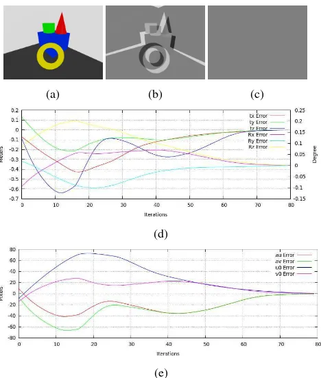
In this Section, simulation results are presented to validate our approach. We use a 3D scene composed by four simple geometric meshed objects as test environment (figure 4).
Figure 4: Virtual 3D test environment
A virtual camera is placed inside the 3D environment and a vir-tual image is generated from this pose. The intrinsic virvir-tual cam-era parameters are known. We consider this virtual image as the desired imageI∗(figure 5a).
The virtual camera is randomly moved inside a sphere of 0.2 me-ters around the desired pose. The camera orientations are ran-domly incremented by an angle between -5 and 5 degrees around its three axes. The intrinsic camera parameters are randomly in-cremented by a number between -20 and 20 pixels. A virtual image is generated with these new camera extrinsic and intrinsic parameters. This image is considered as the initial image. We use the photometric virtual and visual servoing from this initial pose. Figure 5b shows the image differences between the desired and the initial image. Figure 5c shows the image differences between the desired and the image generated at the end of the servoing. We can see that the virtual camera has converged to the desired cam-era pose (figure 5d) by minimizing the residual error between the desired image and the images generated during the servoing. The intrinsic camera parameters have also been correctly estimated as shown by the figure 5e.
This experiment has been repeated one hundred times with ran-domly extrinsic an intrinsic parameters. The virtual camera pa-rameters have successfully converged to the desired papa-rameters
(a) (b) (c)
(d)
(e)
Figure 5: Simulated experiment : (a) desired image, (b) differ-ences between desired and inital image, (c) differdiffer-ences between desired and final image, (d) translations and rotations error, (e) intrinsic camera parameters error
for 95 experiments. The 5 others experiments have failed because the overlap of the geometric objects projection in the desired im-age and in the initial imim-age was not enough.
5. COLORIZATION RESULTS
5.1 Methodology
The estimated pose allows us to transform each point of the cloud into the digital image frame. The 3D point cloud data are initially expressed in object reference frame. We use thecMofrom our pose estimation to express the point cloud in the camera refer-ence. Then, using the perspective projection (3) with the esti-mated intrinsic camera parametersK, we express the points into the 2D digital image planeI∗. Our points have now real coordi-nates included in the digital image dimensions. We use a bilinear interpolation to assign a new color value to each 3D point. This RGB color value is computed with the weighted average of the RGB values of the four neighboring pixels in the digital image. In most cases, the colorization or the texturing is done when the point cloud is meshed. In our case, we want to colorize directly the original point cloud. Because of that, we can not expect good colorization results without handling the occlusion issues. Indeed some points coming from parts of the scene which are invisible from the camera position may be considered as visible and col-ored. This can occur in two situations: when two (or several) points from different depths are on the same projected ray and so are projected into a same pixel or when every points, projected in a pixel, come from invisible parts of the scene. In these two cases, points, which are supposed to be invisible, receive a false new color. To fix these issues, before the colorization we ap-ply the Hidden Point Removal (HPR) (Katz et al., 2007) on the point cloud to remove the 3D points which should be invisible as viewed from the estimated posecM
5.2 Experimental results
First Experiment : we use our approach to colorize the point
cloud of the south portal shown in figure 2 with the digital image shown in figure 6a. The camera is calibrated, so its intrinsic pa-rameters are known.
(a)
(b)
(c)
Figure 6: Colorization of the south portal : (a) desired digital image, (b-c) colorized point cloud, (e) evolution of the residual error during the servoing
We use our method to determine from where the digital image has been taken (in the 3D scene which contains the point cloud). The virtual and visual servoing moved the virtual camera by com-puting iteratively its six degrees of freedom and reached a stable state after 17 iterations. Figure 7 shows the evolution of the resid-ual error during the servoing. Figure 8 represents the difference between the digital image that we want to reach and the virtual one at the first (a) and the last (b) iterations. The distance between the initial virtual camera pose and the optimal one is 674.50mm.
Figure 7: Evolution of the residual error during the servoing
With the estimated camera posecM
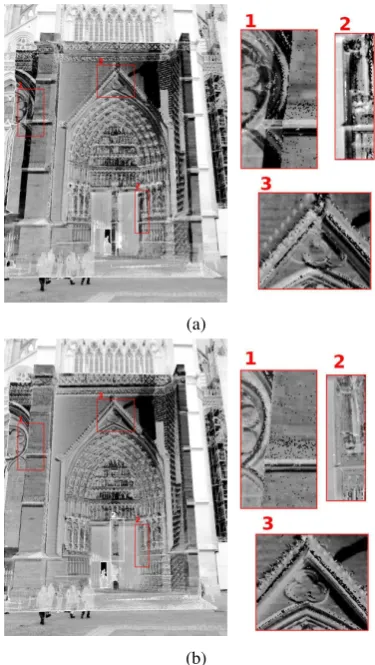
o, the visible points ofPCm are projected in the digital imageI∗(figure 6a) and are colorized. Figure 6b and figure 6c show the point cloudPCmafter its col-orization. We obtain a point cloud which seems perfectly colored, with much more uniform colors but if we closely look at the cloud (figure 9), we can see that we need to have several digital images for covering the portal entirely. We can also see the lack of ac-curacy on the statue face because of a bad digital image point of
(a)
(b)
Figure 8: Differences images between the desired digital image and (a) the intial image (b) the final image
view choice. To improve the detail visibilities we need a better image resolution for the colorization. Therefore, we have to take images from nearest positions from the statue.
Figure 9: The south portal point cloud colorized. The points re-colorized in red are invisible from the digital image pose
Second experiment : we use our pose optimization method to
projected in one different pixel. Knowing the intrinsic camera parameters and the point cloud resolution, we computed the dis-tance needed between the object and the camera to ensure that a pixel receives a unique projected 3D point. Empirically, we cal-culated a four meters distance needed between the statue and our camera to project each visible 3D point in one different pixel in the 2D image. Three digital images have been takenI∗1, I∗2,I∗3
around the statue for a maximum covering (figure 10). The three
Figure 10: Images of the Virgin Mary used to the colorization (These digital images have a 4032x3024 pixels resolution)
camera poses are estimated with the pose estimation presented before and we use our complete colorization process. Right now, the points colorization is done one image after the other. Points are projected in the first digital image, points covered by this one are colored and the others are labelled as not yet colored. Then, points are projected in a second digital image and only the cov-ered and labelled points are colorized. This operation is repeated with all the digital images or when all the points are colorized. A comparison between the Virgin Mary point cloud before and after our colorization is shown in Figure 11. We took another
(a)
(b)
Figure 11: The Virgin Mary point cloud (a) before and (b) after our colorization.
digital imageI4of the Virgin Mary from a different view angle for a visual validation. This image has not been used for the point
cloud colorization. Figure 12 shows the Virgin Mary point cloud from the same camera pose than the new image after and before our colorization process. As we can see, the good colorization results are clearly undeniable. The two images focused on the Virgin’s face (Figure 12) show us the really accurate color reso-lution of the point cloud after its colorization. The digital image
I4 has been taken 5 months (different season) after we took the three imagesI∗1,I∗2,I∗3used for the colorization. This explains the colorimetry slight differences betweenI4and the colored point cloud.
(a) (b) (c)
(d)
(e)
(f)
Figure 12: (a) A Virgin Mary statue image from a low-angle shot. (b) The original point cloud of the Virgin Mary from the same camera pose. (c) The colored point cloud of the Virgin Mary from the same camera pose. (d-f)A focus on the color resolution of the Virgin’s face.
Third Experiment : we also used the colorization process on
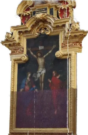
Figure 13 shows a comparison between the point cloud colors acquired by the scanner (bottom area) and after its colorization (top area).
Figure 13: Painting in the chapel of the Saint-Sebastian before (bottom) and after (top) its colorization.
Fourth Experiment : thanks to the intrinsic camera parameters
estimation, we can also use digital images without any informa-tion about the camera which took them. We colorize a part of the point cloud of the western faade portal using a digital image from the internet (figure 14a).
6. CONCLUSIONS AND FUTURE WORKS
We proposed an alternative method for automatically registering digital images over 3D point cloud. The existing manual meth-ods used to detect the correspondence features of the two data sets can provide good results. However, these methods can be really tedious to handle an important size of data. Automatic detec-tions of geometric features can be delicate because they require to have similarities between the digital images and the virtual im-ages generated with the 3D point clouds.
In our approach, rather than using geometric image features, we use the entire image intensities which make the registration more robust and precise than by manually selecting points. In the fu-ture, it seems interesting to use the RGB information rather than only the intensities.
The optimization of the intrinsic camera parameters allows to use digital images without any informations about the camera which took them. The presented results show that our process provides point clouds with a realistic texture quality. Future works will be focused on the research of the optimal positions needed to obtain digital images to colorize a point cloud.
REFERENCES
Abmayr, T., Hartl, F., Mettenleiter, M., Heinz, A., Neumann, B. and Fr02hlich, C., 2004. Realistic 3d reconstruction - combining laserscan data with rgb color information.
Adan, A., Merchan, P. and Salamanca, S., 2012. Creating Re-alistic 3D Models From Scanners by Decoupling Geometry and Texture. International Conference on Pattern Recognition (ICPR) pp. 457–460.
(a)
(b)
Figure 14: (a) Digital image of a part the western fac¸ade portal from the internet. (b) Point cloud of the western faade portal with points colored using the digital image
Al-kheder, S., Al-shawabkeh, Y. and Haala, N., 2009. Develop-ing a documentation system for desert palaces in Jordan usDevelop-ing 3D laser scanning and digital photogrammetry. Journal of Archaeo-logical Science 36(2), pp. 537–546.
Alshawabkeh, Y. and Haala, N., 2004. Integration of digital photogrammetry and laser scanning for heritage documentation. IAPRS pp. 12–23.
Altuntas, C., Yildiz, F., Karabork, H., Yakar, M. and Karasaka, L., 2007. Surveying and documentation of detailed historical heritage by laser scanning. XXI International CIPA Symposium pp. 01–06.
Belkhouche, Y., Buckles, B., Duraisamy, P. and Namuduri, K., 2012. Registration of 3d-lidar data with visual imagery using shape matching. Int. Conf. on Image Processing, Computer Vi-sion, and Pattern Recognition pp. 749–754.
Benhimane, S. and Malis, E., 2004. Real-time image-based tracking of planes using efficient second-order minimization. IEEE/RSJ International Conference on Intelligent Robots and Systems pp. 943–948.
Collewet, C. and Marchand, E., 2011. Photometric Visual Servo-ing. IEEE Transactions on Robotics 27(4), pp. 828–834.
Comport, A., Marchand, E. and Chaumette, F., 2003. A real-time tracker for markerless augmented reality. In: ACM/IEEE Int. Symp. on Mixed and Augmented Reality, ISMAR, Tokyo, Japon, pp. 36–45.
Sets on Approximate Geometry. International Journal of Com-puter Vision 102(1-3), pp. 91–111.
Corsini, M., Dellepiane, M., Ponchio, F. and Scopigno, R., 2009. Image-to-geometry registration: a mutual information method exploiting illumination-related geometric properties. Computer Graphics Forum 28(7), pp. 1755–1764.
Haddad, N. A., 2011. From ground surveying to 3D laser scanner: A review of techniques used for spatial documentation of historic sites. Journal of King Saud University - Engineering Sciences 23(2), pp. 109–118.
Henry, P., Krainin, M., Herbst, E. and Ren, X., 2012. Rgb-d map-ping : Using kinect-style depth cameras for dense 3d modeling of indoor environments. The International Journal of Robotics Re-search 31(5), pp. 647–663.
Huber, P. J., 1981. Robust Statistics. John Wiley and Sons.
Ikeuchi, K., Oishi, T. and Takamatsu, 2007. The great buddha project: Digitally archiving, restoring, and analyzing cultural her-itage objects. Int. J. Comput. Vision 75(1), pp. 189–208.
Katz, S., Tal, A. and Basri, R., 2007. Direct visibility of point sets. ACM Trans. Graph. 26(3), pp. 24.
Marchand, E. and Chaumette, F., 2002. Virtual visual servoing: A framework for real-time augmented reality. In: Eurographics Conference Proceeding, Vol. 21(3), pp. 289–298.
Mastin, A., Kepner, J. and Fisher, J., 2009. Automatic registration of lidar and optical images of urban scenes. IEEE Conference on Computer Vision and Pattern Recognition pp. 2639–2646.