Polarization Stereoscopic Imaging Prototype
Mohammad Iqbal
1, Fabrice Mériaudeau
2, Olivier Morel
21
Lab LE2i CNRS UMR 5158, Université de Bourgogne, France.
Gunadarma University, Indonesia.
[email protected]
2Lab LE2i CNRS UMR 5158,Université de Bourgogne, France.
[email protected], [email protected]
Abstract
Understanding the polarization of light is becoming increasingly important in the study of non linear optics in computer vision. This is caused by the polarization state of light can provides an essential information concerning the observed surface orientations more proficient than the intensity information from conventional imaging system in many light condition. That is the reason why polarization imaging system can be widely uses for many application in computer vision field, such as object recognition, shape estimation or object segmentation. In the other side, stereo vision infers scene geometry from images pair with different viewpoints. Using Stereo vision can improve image understanding technique by obtaining depth information from pairs of digital images. Partially, many researchers have been done a lot of method in both imaging vision technique. However, there is very little research to combine the stereo vision with polarization imaging. The motivation of proposed work is come from nature, from many animals that use two eyes to sense a polarization light as a further source of visual information. The developed prototype is made of a stereo camera set-up with two liquid crystal components in front of the lenses. This article also describes the geometric and the photometric calibration process that is required and provides algorithms that enable to extract both three-dimensional information and polarization information.
Keywords: Stereo Vision, Stereo Matching, Polarization Imaging
1. Introduction
Beside polarization vision ability, in the nature, some insects also use two eyes to see and identify object. It’s mean they utilize a stereo vision system besides their ability to extract polarization information from the light. The stereo vision system is a well polarization images without losing polarization information, and how to extract and present the polarization information such as the ability of these insects.
We try combine the advantage from polarization imaging and stereo vision system. The text starts with an introduction into imaging polarimetry and stereo vision, an efficient technique for measuring light polarization from stereo images, and moves onto some test and evaluation to present improved result from Polarization stereoscopic imaging prototype. The final aim is to develop a low price polarization sensitive camera setup with parallel acquisition using a stereo system.
2. Previous Work
Polarization vision has been used for image identification [18], Shape estimation [22] and dielectric or metal discrimination [13]. Analysis of the polarization pattern caused by surface reflection has been done to provide constraints on surface geometry. This research applies to specular reflection and to diffuse reflection ; the directionality of the molecular electron charge density, interacting with the electromagnetic field of the incident light [13]. It is obtained when un-polarized light is reflected from a surface, and becomes polarized [4]. Most of research aimed to extracting information from polarization data. It involves by placing a linear polarizer in front of a camera and taking images of an object or a scene with the polarizer oriented at different angles [5, 12]. For polarization sensitive imaging system, some research started by [15],[16],[17] with two designs polarization camera ; Setup with two CCD cameras using a beam splitter in front of them.The application with beam splitter [11] was used for clinical mapping of skin cancer. Other work has involved experimenting with liquid crystal technology to enable rapid acquisition of polarization images [11].
The comprehensive stereo vision research in [2], done to categorize all many methods exist for combining information about an scene (or object) from two or more views. Partially, many researcher done many technique to solve a problem in stereo system, such as geometric calibration to obtained intrinsic parameters of the two cameras (focal length, image center, parameters of lenses distortion) and extrinsic parameters (rotation and translation that aligns the two cameras) [11]. Computing rectifying homographies for stereo vision [1],[3] and also research about methodology for the evaluation of (binocular) stereo vision algorithms [7].
and also having strong reflection polarization. Using this technique, any polarization pattern in the nature can be measured and visualized in three dimensions.
3. Polarization Vision
Three polarization parameters can be measured by a simple set up ; the intensity of light, angle of polarization and degree of polarization. Intensity of Light is the quantity perceived by human vision and can be recorded by imaging sensors as time averaged energy, and the other two parameters can not be perceived by unassisted eyes or conventional imaging sensor. The angle of polarization is orientation of the polarized component in a partially linearly polarized light with respect to a certain reference, varies from 0 to a maximum value of 180 degrees. Degree of polarization (also referred to as partial polarization) could be defined as the relative proportion of the linearly polarized component in a partially linearly polarized light. It varies from zero (completely un-polarized) to one (completely linearly polarized light).
Polarization state or partial linear polarization of light can be measured using linear polarizer installed in front an imaging sensor. Incident lights result in partially linearly polarized and linearly polarized will be a sinusoids which having a non-zero and zero values for their minima respectively. A sinusoid can be characterized using three polarizer condition only. For that, three different images captured with a polarizer oriented at three different angles between 0°-180° are required. Following the work of [7],[11], three different intensity are taken from image intensity measurements at polarizer angles 0°, 45° and 90° (I0, I45 and I90 ), and the partial linear polarization
Intensity
The degree of Polarization
The angle of Polarization (7)
4. Stereo Vision
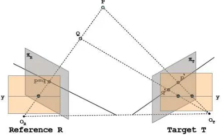
The computational stereo in computer vision field has been known for more than 20 years and two main problems involve in this area, first the correspondence problem ; how to find a correct point in the left image associated with a point in the right image , and the second is the reconstruction problem ; step to recover 3D points from known point matches. Reconstruction problem can be found by triangulation, this is a relatively simple step. But, the correspondence problem is more challenging because it should facing photometric distortions and noise, specular surfaces and transparent objects, perspective distortions Uniform/ambiguous regions, repetitive/ambiguous patterns, or occlusions and discontinuities. To simplify the correspondence problem, many researcher exploit the epipolar geometry, by searching for the point correspondence along an epipolar line. In general, epipolar lines are not aligned with coordinate axis. To reduce time consuming point match searches, by comparing pixels on skew lines in image space, we need a method to rectify images [1] to determine transformations of each image plane such that pairs of conjugate epipolar lines become collinear and parallel to one of the image axes (usually the horizontal one, see fig. 1).
Figure 1. Strategy to solve the correspondence problem
Figure 2. Implementation Local Matching Cost Computation
5. Material and Method
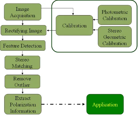
The Imaging system setup must be able to accommodate images from stereo vision system as well as images from polarization imaging system. Two calibration steps are required: first, a photometric calibration to estimate the orientation of the polarizer. Second, a geometric calibration to compute images correspondence from stereo imaging. Rectify stereo images process needed to facilitate image processing to find pixel by pixel correspondence between left and right images in hori zontal line of scene, rows by rows.
Figure 3. Flowchart system
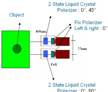
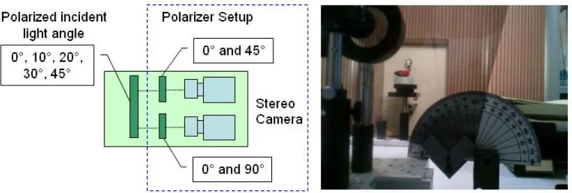
5.1. Imaging System
Figure 4. Imaging system setup
5.2. Calibration
There is two vision system working in this imaging system installation ; Polarization imaging system and stereo imaging system. Calibration is the important step to ensure both system run convenient with the actual circumstances in this experiment environment.
5.2.1. Polarization Calibration : First calibration in polarization imaging system, to get the accuracy of the measure of the polarization angle after reflection from some surface, we used very precisely polarizing filter and control fine tunings time evolution of incident light. The polarization angle is estimate by placing another linear polarizing filter in front our polarizing filter setup and capturing multiple frames for different orientation of the polarizer (see fig. 5).
Figure 5. Polarization Calibration system setup. Mpol1&Mpol2 is mueller matrix
from linear polarizer, s, s’,s’’ is incident light polarization state.
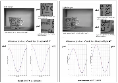
Figure 6. Polarization Calibration Result
Computation is using eq. (4) to (7)) for each pictures in left and right camera separately. The expected polarization intensity is calculated by least square method and compare to the mean intensity measured. Ideally, the difference should be zero. But a slight difference of one or two grey levels can be tolerated at scaled of 256 grey levels. Higher difference between expected and measured result means the images are too much noise (see fig. 6).
5.2.2. Geometric Calibration : Second calibration in the stereo imaging system. It needed to get accurate information about the internal and external camera parameters from geometry computation. We were captured ten pairs of calibration pattern images. The system was calibrated using the Matlab camera calibration toolbox from J.Y. Bouguet [12]. Images were rectified using the method proposed by [1].
5.3. Feature Detector, Stereo Matching and Remove Outliers
(8)
I1 and I2 are the source images respectively and S(x,y,d) is the result of normalized
sum of squared differences of the pixel (x,y). Disparity calculated using a m × n window. d is the offset in the target image (right camera) with respect to the pixel (x,y) in the reference image (left camera).
Once the point matches were computed, outliers are removed using RANSAC method [19], [21]. This approach fits a fundamental matrix to a set of matched image points.
5.4. Extract Polarization Information
The imaging setup in this research can produce 4 polarized images ; 0° and 90° in the left camera and 0° and 45° in the right camera. To obtain the polarization state of incident light we just need capture three different intensity images through a set of polarization filters. I0 = (I0left + I0right)/2, I45right and I90left are a representation of the
image intensity measurements taken at an angle of polarizer of 0°, 45° and 90° . The angle of polarization, the degree of polarization and the intensity can be obtained based on equations (1) to (3) above. From equation (4) :
and we got a angle of polarization :
45
From the angle of polarization, we can compute the degree of polarization :
45 matching algorithm described in the previous step.
6. Result
This is the important step to proof that we can extract polarization state from stereo system. First, try to validate angle of polarization founded from proposed system is correct as angle of polarization in nature. Second, choosing polarizer intensity to accomodate stereo matching computation, to enhanced extract polarization computation based-on that matching result.
6.1. Validating Angle of Polarization Information
Figure 7. Validating Angle of Polarization Result
In this work, we use a Indonesian traditional puppet called wayang as object. To ensure the calculation of the polarization state of the light is correct, we were set the polarized incident light condition with a known angle. This step can be achived by inserting a polarizer in front of the setup system (see fig. 7). Five set conditions of incident light (0 °, 10 °, 20 °, 30°, 45°) were used and compared with the angle of Polari zation obtained with our method (Table 1).
Table 1. Average Results of Polarization Information for each scenes Incident Light (0°,10°,20°,30°,45°)
Incident Light angle
Average result Angle of Pol
% of Average Error Angle of Pol
0° 2.1586 0.0216
10° 8.7851 0.1879
20° 16.0545 0.3605
30° 26.6184 0.5662
45° 39.7027 0.8470
Table 1 present an average result from computation of extract angle of polarization by our system obtained from each pixel found by mathing algorithm, comparing with polarized incident light angle.
6.2. Choosing Polarizer Intensity To Enhance Stereo Matching Result
the quality of the polarization information result. Here, again, we were validating the best combination of polarizer setup in our system, to get the best stereo maching result.
Table 2. Combination Polarization Intensity for Input Imaging System
Setup Left camera Right Camera
Data 1 0° 0°
Data 2 (0°+90°) / 2 0°
Data 3 (0°+90°) / 2 45°
Data 4 (0°+90°) / 2 (0°+45°) / 2
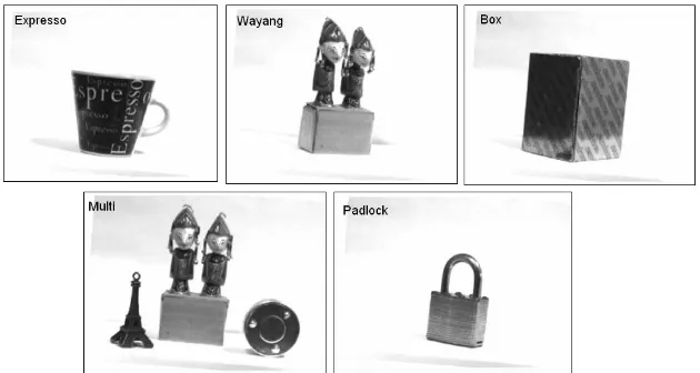
This parts are uses a similar technique with validating Angle of Polarization Information technique above. But we do some combination images with polarization intensity for left and right camera as illustrated in table 2. We also implement our imaging system setup for 5 different object (see fig. 8). Each object represents a specific properties, such as opaque objects (expresso), specular (wayang, padlock), object with simple (box) and complex scene(multi).
Figure 8. Test Object for Enhance StereoMatching result
0
All Point found Avg Point Found/scene
Figure 9. Bar chart for Point found in various object
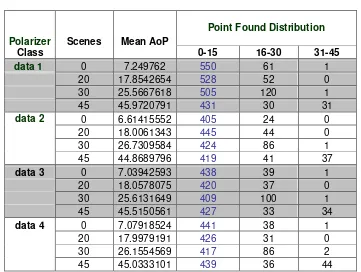
The result of polarization information and distribution of point found can be seen in table 3. Here, for distribution of point found, we make some normalization data. For each scenes, we normalized to zero. Column 0-15 denote the values of point found in that region (near area from zero – good result).
For Angle of Polarization result, we can see all class combination of polarization intensity, give a similar result, if we compare angle of polarization with scenes of incident light (10 °, 20 °, 30°, 45°). But if we consider accuracy of point found distribution, class Data 1 give a better result than the other, because most point distribution found in area 0-15, that very close with the right places.
6.3. Multi Orientation Filter in One Scene
In this section, experiments conducted to see more clearly the variation of polarized light originating from reflection on the object, which successfully extracted from one scene. In the real objects in nature, the light that reflected on an object would have many variations in orientation. Therefore, this experiment is to show this setup have the ability to capture the variations of incident light and extract polarization information with the proper orientation and use it for further processing such as 3D shape reconstruction, segmentation or object identification.
Figure 10. Multi Orientation Filter Setup
Visually, the algorithm were able to extract the polarization state in accordance with the actual situation. It is still have a few mistakes orientation of angle of polarization extracted. We doing this experiment to another object (fig. 12) and our setup still provide a close result to actual incident light status.
Figure 12. Angle of Polarization result with Multi Orientation Filter with other object
7. Conclusion
The main advantage of this method are simplicity of installation. Set up only takes two general CCD camera with a polarizer rotator in front of stereo camera. Each image was taken twice sequentially to get four polarized images (0° in left and right, 45° in right and 90° in left). The important issues to get the accuracy of the extracted polarization component is depend on the stereo point matching results from the extracted features in the previous step. More features are detected, will affect to higher possibility matching points found and in the end higher polarization state component extracted. That is why an important improvement to be done in this section.
We presented a simple but novel technique for extracting polarization state component from points correspondence a pair of calibrated polarization images. Our stereo polarization system design with liquid crystal polarizer in every camera can capture 4 polarized images with different orientation of polarizer, and also sensitive polarization state component. Experiments show that our method gives good performance in complex background, especially when there is some light reflected from specular parts.
Acknowledgment
References
[1] A. Fusiello, E. Trucco and A. Verri, "A compact algorithm for rectification of stereo pairs", Machine Vision and Applications Springer Journal, Vol12 Number 1:pp 16-22 July, 2000
[2] Brown, Myron Z. et al, “Advances in Computational Stereo”, IEEE TRANSACTIONS ON PATTERN
ANALYSIS AND MACHINE INTELLIGENCE, VOL. 25, NO. 8:pp 993-1008, 2003.
[3] C. Loop, Z. Zhang, "Computing rectifying homographies for stereo vision", Proc. IEEE Computer Vision and Pattern Recognition, Vol.1 :pp 125-131, Juni 1999.
[4] D. Goldstein, “Polarized Light book”, Second Edition, CRC Press, ISBN-13: 9780824740535, 2003.
[5] David G. Lowe, "Distinctive image features from scale-invariant keypoints," International Journal of Computer Vision, 60, 2, pp. 91-110., 2004
[6] D. Miyazaki, M. Kagesawa, and K. Ikeuchi. Transparent surface modelling from a pair of polarization images. IEEE Trans. Patt. Anal. Mach. Intell., 26:73–82, 2004.
[7] D. Scharsteinand R. Szeliski, “A taxonomy and evaluation of dense two-frame stereo correspondence algorithms”Int. Jour. Computer Vision, 47(1/2/3):7–42, 2002
[8] Ferenc Mizera, Balázs Bernáth, György Kriska, and Gábor Horváth, "Stereo Videopolarimetry: Measuring and Visualizing Polarization Patterns in Three Dimensions, JOURNAL OF IMAGING SCIENCE AND TECHNOLOGY® • Volume 45, Number 4, July/August , 2001
[9] Gary A. Atkinson and Edwin R. Hancock, Multi-view Surface Reconstruction using Polarization, Proceedings of the Tenth IEEE International Conference on Computer Vision (ICCV’05), 1550-5499/05, 2005
[10] Iqbal, M.; Morel, O. & Meriaudeau, F. Choosing Local Matching Score Method for Stereo Matching Based-on PolarizatiBased-on Imaging IEEE, The 2nd InternatiBased-onal CBased-onference Based-on Computer and AutomatiBased-on Engineering (ICCAE 2010), Vol, 2010, 2, 334-339
[11] J. C. Ramella-Roman, K. Lee, S. A. Prahl, S. L. Jacques, "Polarized Light Imaging with a Handheld Camera", SPIE Saratov Fall Meeting 2002: Optical Technologies in Biophysics and Medicine IV, Vol 5068, p284-293, 2003.
[12] J.Bouguet. Matlab camera calibration toolbox, Website Caltech.Edu http://www.vision.caltech.edu/bouguetj/calib doc/index.html, 2008.
[13] L.B. Wolff, “Polarization Bases Material Classification from specular reflection”, IEEE transactions on
Pattern Analysis and Machine Intelligence, Vol 12:pp. 1059-1071, 1990.
[14] L. B. Wolff and T. E. Boult. Constraining object features using a polarisation reflectance model. IEEE Trans. Pattern Anal. Mach. Intell, 13:635–657, 1991.
[15] L.B. Wolff, "Applications of Polarization Camera Technology", IEEE EXPERT, Vol 10, No. 5, pp. 30-38., October 1995.
[16] L.B. Wolff and A. Andreou, “Polarization Camera Sensor” Image and Vision Computing Journal, Vol 13 Number 16: pp. 497-510 , 1995.
[17] L.B. Wolff, T.A. Mancini, “Liquid Crystal Polarization Camera”, IEEE Transaction On Robotics and
Automation, Vol. 13, No. 2 p195-197, April 1997.
[18] L.B. Wolff, “Polarization Vision : a new sensory approach to Image Understanding”, Image and Vision
Computing Elsevier Journal, Vol 15:pp. 81-93, 1997.
[19] P. D. Kovesi, MATLAB and Octave Functions for Computer Vision and Image Processing, School of Computer Science & Software Engineering, The University of Western Australia, http://www.csse.uwa.edu.au/~pk/Research/MatlabFns/, 2009.
[20] Mikolajczyk, K. & Schmid, C. "Indexing based on scale invariant interest points", In Proceedings of the 8th International Conference on Computer Vision,, p525-531, 2001
[21] M. A. Fischler and R. C. Bolles, “Random sample consensus: A paradigm for model fitting with applications to image analysis and automated Cartography”, Communications of the ACM, vol. 24:pp. 381-395, June 1981.
[22] Morel, O., Stolz, C., Meriaudeau, F. & Gorria, P. “Active Lighting Applied to 3D Reconstruction of Specular Metallic Surfaces by Polarization Imaging Applied Optics”, 45, p4062-4068, 2006
Authors
Mohammad Iqbal was born in Bogor, Indonesia, on 1975. He finished his degree in computer science in 1998 from the Gunadarma University, Depok, Indonesia and received his master degree in 2001 in Magister Management of Information System from the same University. Since February 2008, he was a doctoral student at University of Burgundy, in LE2I Lab, IUT Le Creusot, France. He served as staff in Gunadarma University, Indonesia (1998-2001) and heads of Data Processing Faculty of Industrial Technology in Gunadarma University (2001-now) where he is engaged in teaching an researching on computer architecture and networking, computer security and Robotics. His research interests include computer vision and optics, digital image processing, robotics, computer networking and Security.
Fabrice Mériaudeau was born in Villeurbanne, France, on 1971. He received the M.S. degree in physics, the engineering degree (FIRST) in material sciences in 1994, and the Ph.D. degree in image processing in 1997 from Dijon University, Dijon, France. He was a Postdoctoral Researcher for one year with The Oak Ridge National Laboratory, Oak Ridge, TN. He is currently a Professor at University of Burgundy, the Head of the University Center Condorcet, and the Director of the Le2i, Research unit from CNRS (Centre National de la Recherche Scientifique) 5158, IUT Le Creusot, Université de Bourgogne, France. He is also currently the coordinator of an Erasmus Mundus Master in the field of computer vision and robotics. He has authored or coauthored more than 150 international publications. He is the holder of three patents. His research interests are focused on image processing for artificial vision inspection, particularly on nonconventional imaging systems (UV, IR, polarization, etc.).