Configuring IPCop Firewalls
Closing Borders with Open Source
How to set up, configure, and manage your Linux
firewall, web proxy, DHCP, DNS, time server, and VPN
with this powerful Open Source solution
Barrie Dempster
James Eaton-Lee
Configuring IPCop Firewalls
Closing Borders with Open Source
Copyright © 2006 Packt Publishing
All rights reserved. No part of this book may be reproduced, stored in a retrieval system, or transmitted in any form or by any means, without the prior written permission of the publisher, except in the case of brief quotations embedded in critical articles or reviews.
Every effort has been made in the preparation of this book to ensure the accuracy of the information presented. However, the information contained in this book is sold without warranty, either express or implied. Neither the authors, Packt Publishing, nor its dealers or distributors will be held liable for any damages caused or alleged to be caused directly or indirectly by this book.
Packt Publishing has endeavored to provide trademark information about all the companies and products mentioned in this book by the appropriate use of capitals. However, Packt Publishing cannot guarantee the accuracy of this information.
First published: September2006
Production Reference: 1160906
Published by Packt Publishing Ltd. 32 Lincoln Road
Olton
Birmingham, B27 6PA, UK.
ISBN 1-904811-36-1
www.packtpub.com
Credits
Authors
Barrie Dempster James Eaton-Lee
Reviewers
Kyle Hutson Lawrence Bean
Development Editor
Louay Fatoohi
Assistant Development Editor
Nikhil Bangera
Technical Editor
Saurabh Singh
Editorial Manager
Dipali Chittar
Indexer
Mithil Kulkarni
Proofreader
Chris Smith
Layouts and Illustrations
Shantanu Zagade
Cover Designer
About the Authors
Barrie Dempster is currently employed as a Senior Security Consultant for
NGS Software Ltd, a world-renowned security consultancy well known for its focus in enterprise-level application vulnerability research and database security. He has a background in Infrastructure and Information Security in a number ofspecialized environments such as financial services institutions, telecommunications
companies, call centers, and other organizations across multiple continents. Barrie has experience in the integration of network infrastructure and telecommunications systems requiring high caliber secure design, testing, and management. He has been involved in a variety of projects from the design and implementation of Internet banking systems to large-scale conferencing and telephony infrastructure, as well as penetration testing and other security assessments of business-critical infrastructure.
James Eaton-Lee works as a Consultant specializing in Infrastructure Security; he
has worked with clients ranging from small businesses with a handful of employees to multinational banks. He has a varied background, including experience workingwith IT in ISPs, manufacturing firms, and call centers. James has been involved in
the integration of a range of systems, from analog and VoIP telephony to NT and AD domains in mission-critical environments with thousands of hosts, as well as
UNIX & Linux servers in a variety of roles. James is a strong advocate of the use of
appropriate technology, and the need to make technology more approachable and
flexible for businesses of all sizes, but especially in the SME marketplace in which technology is often forgotten and avoided. James has been a strong believer in the
relevancy and merit of Open Source and Free Software for a number of years
and—wherever appropriate—uses it for himself and his clients, integrating it fluidly
About the Reviewers
Kyle Hutson is a Networking Consultant for Network Resource Group, Inc.
in Manhattan, Kansas, where he designs, implements, and fixes computers and
networks for small businesses. His networking career spans 15 years, and has
included UNIX, Linux, Novell, Macintosh, and Windows networks. Kyle stumbled upon IPCop while looking for a replacement for a broken firewall appliance. Since
then, he has installed it for several clients. He remains active on the IPCop-user mailing list.
Lawrence Bean
fell out of Computer Science and into Music Education in hissophomore year of college. He graduated from the University of Maine with a Bachelor's in Music Education in 1986 and had a ten year career as a Choral Music Educator in the Kennebunk, Maine school system. His large non-audition groups
won silver at the Events America Choral Festival and his select group was featured
on Good Morning America and in Yankee Magazine for its annual performances
of traditional Christmas carols at the highly acclaimed Kennebunkport Christmas Prelude. Throughout his music tenure he maintained his involvement in computers
as the unofficial "computer dude" for Kennebunk Middle School, as well as
integrating the use of computer applications throughout all aspects of the music education program. He fell back into Computer Science with the offer of a position
as Technology Coordinator at SU#47 in greater Bath, Maine. For the last ten years
he has taught teachers how to teach using technology in the classroom as well as creating and managing all aspects of the technology program from hardware repair
to network design to database management. He completed his Masters in Computer Science at the University of Southern Maine in 2006.
Throughout his technology tenure he has maintained his involvement in music
by bringing the Maine All-State Auditions into the 21st century with on-line
applications, judging, and results processing. Outside of work and school, his
16-year career with The Management barbershop quartet brought two albums,
a district championship, three trips to the international competition stage,
Barbershopper of the Year for the Northeastern District, and the national MENC/ SPEBSQSA Educator of the Year award. In his spare time he presents workshops and
Table of Contents
Preface
1
Chapter 1: Introduction to Firewalls
5
An Introduction to (TCP/IP) Networking 5
The Purpose of Firewalls 7
The OSI Model 10
Layer 1: The Physical Layer 10
Layer 2: The Data Link Layer 11
Layer 3: The Network Layer 11
Layer 4: The Transport Layer 11
Layer 5: The Session Layer 12
Layer 6: The Presentation Layer 12
Layer 7: The Application Layer 12
How Networks are Structured 13
Servers and Clients 14
Switches and Hubs 15
Routers 19
Routers, Firewalls, and NAT 21
Network Address Translation 22
Combined Role Devices 25
Traffic Filtering 26
Personal Firewalls 26
Stateless Packet Filtering 28
Stateful Packet Filtering 28
Application-Layer Firewalling 29
Proxy Servers 31
Other Services Sometimes Run on Firewalls 33
DNS 33
DHCP 36
Chapter 2:
Introduction to IPCop
39
Free and Open Source Software 39
Forking IPCop 41
The Purpose of IPCop 43
The Benefits of Building on Stable Components 43
The Gap IPCop Fills 45
Features of IPCop 46
Web Interface 46
Network Interfaces 48
The Green Network Interface 48
The Red Network Interface 49
USB and PCI ADSL Modems 49
ISDN Modems 51
Analog (POTS) Modems 51
Cable and Satellite Internet 52
The Orange Network Interface 52
The Blue Network Interfaces 53
Simple Administration and Monitoring 53
Modem Settings 55
Advanced Network Services 60
Port Forwarding 61
Virtual Private Networking 63
ProPolice Stack Protection 63
Why IPCop? 64
Summary 64
Chapter 3: Deploying IPCop and Designing a Network
65
Trust Relationships between the Interfaces 65
Altering IPCop Functionality 67
Topology One: NAT Firewall 67
Topology Two: NAT Firewall with DMZ 71
Topology Three: NAT Firewall with DMZ and Wireless 75
Planning Site-To-Site VPN Topologies 79
Summary 80
Chapter 4: Installing IPCop
81
Hardware Requirements 81
Other Hardware Considerations 82
Installation Media 84
Hard Drive Partitioning and Formatting 85
Restore Configuration from Floppy Backup 85
Green Interface Configuration 86
Finished? 87
Drivers and Card Assignment 91
Address Settings 92
DNS and Default Gateway 92
DHCP Server 93
Finished! 94
First Boot 95
Summary 96
Chapter 5: Basic IPCop Usage
97
The System Menu 98
Software Updates 98
Passwords 100
SSH Access 100
Connecting to SSH 101
A Little More about SSH 103
GUI Settings 106
Backup 106
Shutdown 108
Checking the Status of Our IPCop Firewall 109
Network Troubleshooting with Ping 125
Summary 126
Chapter 6:
Intrusion Detection with IPCop
12
7
Introduction to IDS 127
Introduction to Snort 128
Do We Need an IDS? 128
How Does an IDS Work? 129
Using Snort with IPCop 130
Monitoring the Logs 130
Chapter 7: Virtual Private Networks
137
What is a VPN? 137
IPSec 139
A Little More about Deploying IPSec 141
Prerequisites for a Successful VPN 143
Verifying Connectivity 148
Host-to-Net Connections Using Pre-Shared Keys 149
Host-to-Net Connections Using Certificates 150
A Brief Explanation of Certificates and X.509 150
Certificates with IPSec in IPCop 155
Site-to-Site VPNs Using Certificates 157
VPN Authentication Options 157
Configuring Clients for VPNs 158
The Blue Zone 159
Prerequisites for a Blue Zone VPN 160
Setup 160
Summary 160
Chapter 8: Managing Bandwidth with IPCop
163
The Bandwidth Problem 163
The HTTP Problem 164
The Solutions: Proxying and Caching 164
Introduction to Squid 165
Configuring Squid 165
Cache Management 166
Managing Bandwidth without a Cache 167
Traffic Shaping Basics 167
Traffic Shaping Configuration 168
Adding a Traffic Shaping Service 169
Editing a Traffic Shaping Service 170
Summary 170
Chapter 9: Customizing IPCop
171
Addons 171
Chapter 10: Testing, Auditing, and Hardening IPCop
195
Security and Patch Management 195
Why We Should Be Concerned 196
Appliances and How this Affects Our Management of IPCop 198
Basic Firewall Hardening 198
Checking What Exposure Our Firewall Has to Clients 199
What is Running on Our Firewall? 203
Advanced Hardening 204
Stack-Smashing Protector (Propolice) 204
Service Hardening 205
Logfiles and Monitoring Usage 205
Establishing a Baseline with Graphs 205
Logfiles 206
Usage and Denial of Service 207
Logged-In Users 211
Other Security Analysis Tools 212
Where to Go Next? 212
Full-Disclosure 213
Wikipedia 213
SecurityFocus 213
Literature 213
Summary 215
Chapter 11:
IPCop Support
21
7
Support 217
User Mailing Lists 218
Internet Relay Chat (IRC) 218
Returning the Support 218
Summary 219
Preface
IPCop is a Linux-based, stateful firewall distribution that sits in between your Internet connection and your network and directs traffic using a set of rules framed by you. It provides most of the features that you would expect a modern firewall to have, and
what is most important is that it sets this all up for you in a highly automated and
simplified way.
This book is an easy-to-read guide to using IPCop in a variety of different roles within the network. The book is written in a very friendly style that makes this
complex topic easy and a joy to read. It first covers basic IPCop concepts, then moves to introduce basic IPCop configurations, before covering advanced uses of IPCop.
This book is for both experienced and new IPCop users.
What This Book Covers
Chapter 1 briefly introduces some firewall and networking concepts. The chapter
introduces the roles of several common networking devices and explains how
firewalls fit into this.
Chapter 2 introduces the IPCop package itself, discussing how IPCop's red/orange/
blue/green interfaces fit into a network topology. It then covers the configuration of
IPCop in other common roles, such as those of a web proxy, DHCP, DNS, time, and VPN server.
Chapter 3 covers three sample scenarios where we learn how to deploy IPCop, and how IPCop interfaces connect to each other and to the network as a whole.
Chapter 4 covers installing IPCop. It outlines the system configuration required to run
IPCop, and explains the configuration required to get IPCop up and running.
Chapter 5 explains how to employ the various tools IPCop provides us with to
Chapter 6 starts off with explaining the need for an IDS in our system and then goes on to explain how to use the SNORT IDS with IPCop.
Chapter 7 introduces the VPN concept and explains how to set up an IPSec VPN
configuration for a system. Special focus is laid on configuring the blue zone—a
secured wireless network augmenting the security of a wireless segment, even one
already using WEP or WPA.
Chapter 8 demonstrates how to manage bandwidth using IPCop making use of
traffic-shaping techniques and cache management. The chapter also covers the configuration of the Squid web proxy and caching system.
Chapter 9 focuses on the vast range of addons available to configure IPCop to suit our
needs. We see how to install addons and then learn more about common addons like
SquidGuard, Enhanced Filtering, Blue Access, LogSend, and CopFilter.
Chapter 10 covers IPCop security risks, patch management, and some security and auditing tools and tests.
Chapter 11 outlines the support IPCop users have in the form of mailing lists and IRC.
What You Need for This Book
IPCop runs on a dedicated box, and it completely takes over the hard drive, so don't use
a drive with anything valuable on it. It will run on old or "obsolete" hardware, such as a 386 processor, 32Mb of RAM, and 300Mb hard disk. But if you plan on using
some of IPCop's features, such as the caching web proxy, or Intrusion Detection
Logging, you are going to need more RAM, more disk space, and a faster processor.
At least one Network Interface Card NIC is required for the Green Interface. If you will be connecting to the Internet via a cable modem, you will need two NICs.
Once installed you don't need to have a monitor or keyboard attached to the IPCop box, as it runs as a headless server, and is administered over the network with a web browser.
Conventions
In this book, you will find a number of styles of text that distinguish between
different kinds of information. Here are some examples of these styles, and an explanation of their meaning.
There are three styles for code. Code words in text are shown as follows: " In Windows, the ipconfig command also allows the user to release and renew
A block of code will be set as follows:
james@horus: ~ $ sudo nmap 10.10.2.32 -T Insane -O
Starting nmap 3.81 ( http://www.insecure.org/nmap/ ) at 2006-05-02 21:36 BST
Interesting ports on 10.10.2.32:
(The 1662 ports scanned but not shown below are in state: closed) PORT STATE SERVICE
22/tcp open ssh
MAC Address: 00:30:AB:19:23:A9 (Delta Networks) Device type: general purpose
Running: Linux 2.4.X|2.5.X|2.6.X OS details: Linux 2.4.18 - 2.6.7
Uptime 0.034 days (since Tue May 2 20:47:15 2006)
Nmap finished: 1 IP address (1 host up) scanned in 8.364 seconds
Any command-line input and output is written as follows:
# mv /addons /addons.bak
# tar xzvf /addons-2.3-CLI-b2.tar.gz -C / # cd /addons
# ./addoncfg -u # ./addoncfg -i
New terms and important words are introduced in a bold-type font. Words that you
see on the screen, in menus or dialog boxes for example, appear in our text like this:
"We then go back to the addons page, click the Browse button, browse to the file we
just downloaded, click Upload, and the addon is installed on the server."
Warnings or important notes appear in a box like this.
Tips and tricks appear like this.
Reader Feedback
To send us general feedback, simply drop an email to [email protected], making sure to mention the book title in the subject of your message.
If there is a book that you need and would like to see us publish, please send us a note in the SUGGEST A TITLE form on www.packtpub.com or email suggest@ packtpub.com.
If there is a topic that you have expertise in and you are interested in either writing or contributing to a book, see our author guide on www.packtpub.com/authors.
Customer Support
Now that you are the proud owner of a Packt book, we have a number of things to help you to get the most from your purchase.
Downloading the Example Code for the Book
Visit http://www.packtpub.com/support, and select this book from the list of titles
to download any example code or extra resources for this book. The files available
for download will then be displayed.
The downloadable files contain instructions on how to use them.
Errata
Although we have taken every care to ensure the accuracy of our contents, mistakes
do happen. If you find a mistake in one of our books—maybe a mistake in text or
code—we would be grateful if you would report this to us. By doing this you can save other readers from frustration, and help to improve subsequent versions of this
book. If you find any errata, report them by visiting http://www.packtpub.com/ support, selecting your book, clicking on the Submit Errata link, and entering the
details of your errata. Once your errata have been verified, your submission will be
accepted and the errata added to the list of existing errata. The existing errata can be viewed by selecting your title from http://www.packtpub.com/support.
Questions
Introduction to Firewalls
Inthis chapter, we will introduce some firewalling and networking concepts in enough detail to provide a refresher to those who've encountered them already, but in as minimal a fashion as possible, since understanding networking concepts is not
the focus of this book. We feel that some of these concepts are important, and that a
broader picture of how these technologies are used and where they come from serves to better our understanding of the way in which IT works—however, for the reader who is challenged for time, we have tried, wherever possible, to provide italicized
summaries of the knowledge that we feel is important to have about these concepts.
Don't worry if you don't understand all of the concepts we discuss—equally, readers more comfortable with networking concepts should be able to skip ahead. IPCop makes explicit understanding of many of these concepts irrelevant, as it attempts to make administration simple and automated wherever possible. However, if you do feel inclined to learn about these topics in more depth, the introduction given here and some of the URLs and links to other resources that we provide should hopefully be of use. Understanding networking, routing, and how some common protocols work, although not a requirement, will also help you immeasurably if you intend to keep working with systems such as IPCop on a regular basis.
An Introduction to (TCP/IP) Networking
A protocol, within the context of IT and Computer Science, is generally speaking a common format in which computers interchange data for a certain purpose. In networking, a protocol is best compared to a language—the networking situation in the 1970s was one in which there were many different languages and very few interpreters readily available to translate for people.
The resulting research, and most importantly that carried out and funded by the American Department of Defense's Defense Advanced Research Projects Agency
(http://www.darpa.mil), gave birth not only to a range of network protocols
designed for interoperability (that is to say, in order to allow easy, platform-neutral communications between a range of devices), but a network, ARPANet, set up for this express purpose. The best comparison for this within language is the development of the language Esperanto—although the proliferation of this
international language has been fairly minimal, computers have the advantage of not taking years to learn a particular protocol!
This ARPANet was first experimented with using TCP/IP in 1976, and in January of
1983, its use was mandated for all computers participating in the network. By the late 1970s, many organizations besides the military were granted access to the ARPANet as well, such as NASA, the National Science Foundation (NSF), and eventually universities and other academic entities.
After the military broke away from the ARPANet to form its own, separate network for military use (MILNET), the network became the responsibility of the NSF, which came to create its own high-speed backbone, called NSFNet, for the facilitation of internetworking.
When the Acceptable Usage Policy for NSFNet began to permit non-academic traffic,
the NSFNet began, in combination with other (commercial and private) networks (such as those operated via CIX), to form the entity we now know as the Internet. By the NSF's exit from the management of the Internet and the shutdown of the NSFNet in April 1995, the Internet was populated by an ever-growing population of commercial, academic, and private users.
The standards upon which the Internet is based have become the staple of modern networking, and nowadays when anyone says 'networking' they tend to be referring to something built with (and around) TCP/IP, the set of layered protocols originally
developed for use on ARPANet, along with other standards upon which TCP/IP is
implemented, such as 802.3 or Ethernet, which defines how one of the most popular
standards over which TCP/IP runs across in network segments works.
any vendor—our Dell laptop running Microsoft Windows can freely communicate, via TCP/IP, over an Ethernet network using a Linksys switch, plugged into a Cisco Router, and view a web page hosted on an IBM server running AIX, also talking TCP/IP.
More standardized protocols, running on top of TCP/IP, such as HTTP, actually
carry the information itself, and thanks to the layering of these protocols, we can have a vast and disparate set of networks connected that appear transparent to devices such as web browsers and web servers, that speak protocols such as HTTP.
Between our Dell laptop and our IBM server, we may have a dial-up connection,
a frame relay network segment, a portion of the internet backbone, and a wireless
network link—none of which concern TCP/IP or HTTP, which sit 'above' these
layers of the network, and travel freely above them. If only a coach load of children on a school tour could use air travel, ferries, cycle paths, and cable cars, all without stepping from their vehicle or being aware of the changing transport medium
beneath them! Layered communication of the type that TCP/IP is capable of in this
sense is incredibly powerful and really allows our communications infrastructure to scale.
The Purpose of Firewalls
This network and the research underpinning it, originally funded based on the utility for military purposes in one country, has far surpassed its original aims, and through international research and uptake, spawned a phenomenon that is shaping (and will shape) generations to come. Networking is now a core activity not just to governments and research organizations, but also to companies small and large, and even home users. Further developments such as the inception of wireless technology have served to make this technology even more accessible (and relevant) to people at home, on the go, and in the imminent future, virtually anywhere on the surface of the planet!
Many of these networking protocols were originally designed in an environment
in which the word 'hacker' had not yet come to have the (negative) meaning that it nowadays has, and implemented upon a network in which there was a culture of mutual trust and respect. IPv4, the foundation of all communications via the Internet (and the majority of private networks) and SMTP (the protocol used to send electronic mail and relay it from to server to server) are two prime examples of this. Neither protocol, in its initial incarnation, was designed with features designed to maintain the three qualities that nowadays are synonymous with effective communication,
Confidentiality, Integrity, and Availability (called the CIA triad). The CIA triad is
As networking technologies grew and were adopted by governments and large organizations that relied upon them, the need for these three qualities increased, and
network firewalls became a necessity. In short, the need for network security sprung into existence. The Internet has come a long way too from its humble beginnings. As the barrier for entry has decreased, and knowledge of the technologies underpinning it has become more accessible, it has become a decreasingly friendly place.
With growing reliance on the Internet for communications, firewalls have, at
time of writing, become almost universally deployed as a primary line of defense against unauthorized network activity, automated attacks, and inside abuse. They
are deployed everywhere, and the term 'firewall' is used in this context to refer to
anything from a software stack built into commonly used operating systems (such as the Windows firewall built into Service Pack 2 of Microsoft's Windows Operating System (http://www.microsoft.com/windowsxp/using/security/internet/ sp2_wfintro.mspx)) protecting only the computer it is running on, to devices
costing significant sums of money deployed in banks, datacenters, and government facilities (such as Cisco's PIX line of firewall products (http://www.cisco.com/ en/US/products/hw/vpndevc/ps2030/)). Such high-end devices may govern and
restrict network traffic between hundreds of thousands of individual computers. Given this increase in the use of the term 'firewall', and with so many qualifiers added to the word to distinguish between different types of firewall (such as the
terms stateful, proxy, application, packet filter, hardware, software, circuit-level, and many more), it becomes very difficult to know what someone means when they tell you that their network "has a firewall". Our exploration of IPCop, therefore, must begin with an exploration of what a firewall actually is, and armed with this
knowledge, we can then relate IPCop to this knowledge and understand what
function it is that IPCop can fulfill for us.
In order to improve our network security, we need to first identify the problems we need to solve, and determine whether this firewall is the solution to them. Implementing a firewall for the sake of satisfying the buzzword requirement is a
common mistake in security design.
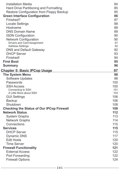
The term firewall refers, generally, to a collection of technologies and devices all designed to do one thing—stop unauthorized network activity. A firewall acts as
a choke point between more than one network (or network segment), and uses a
(hopefully) strictly defined set of rules in order to allow, or disallow, certain types of traffic to traverse to the other side of the firewall. Most importantly, it is a security
In the diagram above, a web server connected to the Internet is protected by a
firewall, which sits in between it and the Internet, filtering all incoming and outgoing traffic. In this scenario, illegitimate traffic from the attacker is blocked by the
firewall. This could be for any number of reasons, such as the service the attacker has attempted to connect is blocked by the firewall from the Internet, because the attacker's network address is blacklisted, or because the type of traffic the attacker is sending is recognized by the firewall as being part of a Denial of Service attack.
In this scenario, the network that the web server sits on (which in a scenario such as this would probably contain multiple web servers) is segmented from the Internet
by the firewall, effectively implementing a security policy dictating what can go from
one network (or collection of networks) to the other. If our firewall disallowed the attacker from connecting to a file-sharing port on the web server, for instance, while
the 'user' was free to access the web server on port 80, the other servers behind the
firewall might be allowed access to the file sharing ports in order to synchronize
content or make backups.
Layered protocols are generally explained using the Open System Interconnection
(OSI) layers. Knowledge of this is extremely useful to anyone working in networking
or with firewalls in particular, as so many of the concepts pertaining to it require
The OSI layers divide traffic and data into seven layers each of which in theory falls into a protocol. Although excellent in theory, networking and IT applications do not always strictly adhere to the OSI Layers, and it is worth considering them to be guidelines rather than a strict framework. That said, they are extremely useful for visualizing connectivity, and in general the vision of layers, each utilizing hardware and software designed by different vendors, each interoperating with the layers above and below is not unrealistic.
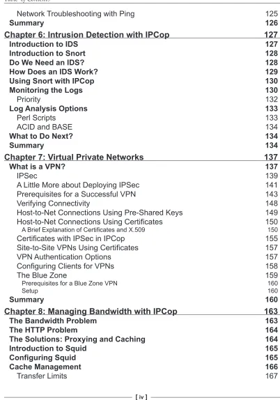
The OSI Model
The OSI model is shown in the following figure:
Layer 1: The Physical Layer
The physical layer encompasses the physical medium on which a network is built.
Layer 2: The Data Link Layer
The data link layer provides connectivity between hosts on the same network segment. MAC addresses are used at the physical layer to distinguish between different physical network adapters and allow them to communicate. Ethernetis a layer-two standard.
Layer 3: The Network Layer
The network layer provides connectivity between hosts on different networks, and it is at this layer that routing occurs. Internet Protocol (IP) and Address Resolution Protocol (ARP) exist at this layer. ARP serves an important purpose, as it intermediates between layer two and layer three by ascertaining the layer-two
(MAC) address for a given layer-three (IP) address.
Layer 4: The Transport Layer
The transport layer, generally, acts as the layer that ensures data integrity. TCP, the protocol most frequently used at this layer, is a stateful protocol that, by maintaining connections with a remote host, can retransmit data that does not reach the
destination. UDP, another (slightly less common) protocol also operates at this layer, but is not stateful—each message it sends is not part of a 'connection' as such, and is treated as entirely separate to a reply (if one is required) or any messages previously passed between two hosts.
IP, TCP/IP, UDP, and other Layer four protocols
As we can see from the examination of the OSI Layers, TCP is a protocol running on top of IP, forming the abbreviation
TCP/IP. Unfortunately, when people use the term TCP/IP, this specific pair of protocols is not always what they mean— the 'TCP/IP Protocol Suite' is quite frequently defined to be IP, TCP, and other protocols such as UDP and ICMP that
are used along with it. This is a distinction that it is worth being aware of, and which is particularly common amongst IT professionals, and in the documentation for operating
Layer 5: The Session Layer
The upper three layers in the OSI model are no longer concerned with (inter-) networking issues as such, and have more to do with the practicalities of software and applications that use connectivity. The session layer is where mechanisms for setting up sessions live, such as the NetBIOS protocol.
Layer 6: The Presentation Layer
The presentation layer handles data-specific issues such as encoding, compression, and encryption. SNMP and XML are standards often used, which exist at this layer.
Layer 7: The Application Layer
The application layer is the layer at which common protocols used for communication live, such as HTTP, FTP, and SMTP.
Generally, Layers three and four, are the ones most commonly dealt with by
firewalls, with a small (but increasing) number, generally referred to as 'proxy firewalls' or 'application-layer firewalls' sitting at layers above this (and being aware
of protocols like HTTP, DNS, RCP, and NetBIOS). It is worth noting that many
firewalls (incorrectly) classify all layers above layer three as application layers.
For our purposes, a thorough understanding (and explanation) of OSI layers and some of the more conceptual and technical aspects of networking are unnecessary— although we have tried to provide some outline of these, this is more for familiarity and in order to give you some idea as to what you may want to learn in future.
For our purposes a knowledge that layering exists is sufficient. If you feel the need
(or are otherwise so inclined) to learn more about these topics, some of the URLs
given in this chapter serve as good starting points for this. You don't necessarily have to understand, agree with, or like the OSI layers in order to work with firewalls (in fact, many TCP/IP stacks do not strictly adhere to segment handling of traffic
based on them), but knowing that they exist and understanding approximately what they're designed to do and how the technologies built around them interact
is important to anyone serious about understanding firewalls or networking or for
anyone who regularly works with these technologies.
Another excellent online resource for information on all things on TCP/IP is
http://tcpipguide.com/.
The IBM "TCP/IP Tutorial and Technical Overview" referenced earlier in this chapter, by Martin W. Murhammer, Orcun Atakan, Stefan Bretz, Larry R. Pugh, Kazunari Suzuki, and David H. Wood, is another good (and free) guide to the world of TCP/IP networking. Although slightly out of date (the last iteration was published in October 1998), many of the standards surrounding TCP/IP have not
changed in over 20 years, so the date should not put you off too much. This guide,
and many others pertaining to open standards and IBM products can be found at the excellent 'IBM Redbooks' site at http://www.redbooks.ibm.com/.
For a published introduction to TCP/IP, the three “TCP/IP Illustrated” books by
Richard W. Stevens are generally considered to be the authoritative source on the
topic. The ISBN number for the complete set is 0-201-77631-6, and it can be found at any good major bookstore or online book retailer.
How Networks are Structured
Whether you know it or not, the chances are that any network that you use is build on top of IP, Internet Protocol. IP and the protocols that are built on top of it (such as
TCP, UDP, and ICMP, all of which use IP datagrams) are the foundation of almost
every network presently deployed. The components that such networks are built
out of are interoperable, and for these reasons their roles are well defined and well understood. We will, briefly, talk about these devices and—particularly—how they interconnect with firewalls.
Ethernet, as the underlying technology on top of which most of these protocols are generally layered, forms the basis of these devices. As such network devices, peripherals, and appliances are often referred to as LAN, Ethernet, or TCP/IP
equipment (or more commonly, just "Network" equipment). There are other networking standards in use, two of them being Token Ring and SNA networks
that have fairly specific uses. Many of theses standards including the two mentioned
above, are generally considered outdated. It is commonly the case that in scenarios in which they are still deployed for legacy reasons, such networks, are hallmarked for replacement or are effectively change-frozen.
As a point of interest, Token Ring and SNA are often deployed in larger organizations,
the latter almost unilaterally in communication with a mainframe such as IBM zSeries. Other specialized IT environments, such as clustering, have specific networking
Here, however, we shall consider the following (Ethernet/IP) network devices:
The server/client relationship is the cornerstone of the TCP/IP protocol and it
is necessary to have some understanding of it in order to be able to effectively administer, implement, and think about it. Put very simply, a client is any device that initiates a connection (i.e. commences sending data) to another computer, and a server is any device that listens for such a connection in order to allow others to connect to it.
Within the context of TCP/IP, all devices on a network are servers and clients, irrespective of whether or not they are specifically assigned the role of server (such
as a corporate mail server) or client (such as a desktop computer). This is for two
reasons: firstly, many higher-level protocols initiate connections back to clients from the server itself; secondly, a TCP/IP connection actually involves data being sent to
listening ports in both connections—initially from the client to the server in order to commence the transaction, connecting (generally) to a well-known port on the server
in order to access a specific service (such as port 80 for HTTP, port 25 for SMTP, or port 21 for FTP) with traffic coming from a (generally) random ephemeral (i.e.
greater than 1024) port on the client.
Once this data arrives, the server sends data to the client (and in this connection, the server is a client!) from the service port and to the (random) port on the client that
was used as the source port for the initial connection. Traffic from the service port
on the server to the client is used in order for the server to reply to the client. Data
flowing in both directions, from client to server and server to client, constitutes a 'whole' TCP/IP connection. This particular distinction becomes important later on when we discuss traffic filtering.
Within the context of a network, a server is a device that provides a fixed service to
hosts on that network. Generally this involves some form of centraliszed resource;
although a 'firewall' may be described as a server it doesn't necessarily have to
accept connections to itself (but rather facilitates connections to other locations
and/or servers).
A server may serve files, email, or web pages, provide network configuration
information via DHCP, provide translation between Domain Names and Host Names and IP addresses acting as a DNS server, or even provide other, more complex services, which facilitate single sign on or provide security services (such as Kerberos servers, radius servers, intrusion detection systems, etc.). For the purposes of this book, we will—generally—consider a server to be a device that provides services and data to other computers and devices on a network.
Clients are generally used directly by users and will be situated on desks and have monitors and input devices plugged into them, or are laptops (servers frequently either share such peripherals or don't have them at all). They are directly used to access resources and information that is sometimes stored elsewhere (such as web
pages or files from a file server) or locally (such as documents stored on a local My Documents folder). For the purposes of this book, we will, generally, consider a client to be a device that a user uses to access services on other computers (and access data stored on them) on a network or on the Internet.
For more information on the client/server relationship, see http://en.wikipedia.org/wiki/Client-server.
Switches and Hubs
The hub is a networking device that allows multiple clients to be plugged into the network segment, within the context of which they can communicate with each other. A hub is, logically, very simple, and essentially acts as a logical connector
for all devices attached to the device, allowing traffic to freely flow from port to
port, such that in a four-port device, if the client attached to port 1 sends data to the client attached to port 4, the hub (unaware of the concept of 'clients') simply allows
this traffic to flow to all ports on this device—clients 2 and 3 ignore the traffic not
Switches address several shortcomings of hubs and are typically deployed in
Switches work by keeping a table in memory correlating ports with MAC addresses, such that the switch knows which computers are plugged into which port. Some switches, which can be 'stacked', apply this to the entire network segment, although in a network in which unmanaged or un-stacked switches were simply connected to each other by crossover cabling, a given switch would simply see a large number of
MAC addresses on a particular port.
Since traffic on local segments (even traffic being routed through that segment and
destined for another network) is passed from host to host (router to router, router to
client, client to server, etc.) directly by MAC address, the switch can make a decision
based on the ports it has, as to for which port a particular datagram is intended. As processing is required, switches have historically been more expensive than hubs, as the electronics required to perform such processing costs more than the 'stupid' components inside a hub.
In terms of their advantages, switches are faster, since any two ports may use a large quantity of bandwidth without affecting the bandwidth available to other ports on
the device. On an unswitched network, if clients 1 and 4 are generating traffic at 90% of the available bandwidth, there is only 10% of the bandwidth (or, practically, less,
when dealing with overhead imposed by IP) available for the rest of the network.
On a switched network, each port, logically, has a significantly increased bandwidth
limit, typically up to the limit of the hardware of the switch.
It is worth noting that many switches will have an overall bandwidth limit for
traffic through all ports, and most medium to higher-end switches have an 'uplink' port, which in addition to providing MDI-X ability (the ability to sense whether a crossover link is required, and if so, perform the necessary modification in the
switch, so a normal 'patch' cable can be used for a switch-to-switch connection) is also a higher bandwidth port (gigabit on a 100 megabit switch), or is a GBIC interface enabling a modular uplink.
Switches are also inherently slightly more secure as it is harder for any device to
arbitrarily listen to network traffic, which may contain private data or authentication
information such as passwords. Switches understand which clients are plugged into which socket on the switch, and will under normal circumstances move data from
one port to another without passing unrelated traffic to computers not acting as
the destination.
This is not, however, an absolute security measure, and may be circumvented using
a technique known as ARP Spoofing or ARP Poisoning (http://www.node99.org/ projects/arpspoof/). ARP Spoofing is a very well-known technique, with several tools existing for multiple platforms in order to allow people to perform it. On a
local segment, ARP spoofing allows any user with administrator or system-level
a laptop, or just a computer configured to boot from CD or floppy disk) to intercept any and all traffic sent by other computers on the same segment, and redirect it
transparently to the Internet (or another destination) without any visible disruption to the user. Once this layer-two protocol is compromised, every other protocol at every other layer (with the exception of strong cryptographic protocols involving
handshakes that are hard to attack, or using certificates) must be considered to be
compromised as well.
Modern switches often have many forms of advanced functionality. Traditional switches, although more intelligent than hubs, are described (in the form in which they were described above) as 'unmanaged' switches. Newer, 'managed' switches (which generally have larger microprocessors, more memory, and increased
throughput (the amount of data that can traverse the network in a given timeframe)) offer more functionality. Some examples of this are the ability to provide added
security features such as MAC address filtering, DHCP snooping, and monitoring
ports. Other such new features may address security and network structure such as vLANs. As mentioned earlier, some 'managed' switches offer a stacking capability,
whereby using a proprietary link cable (such as the 'Matrix' cable with 3com Superstack switches), or a plain patch/crossover cable between the uplink ports
of the switches, a 'stack' of switches can be managed as one, effectively sharing
configuration and management interface.
Some very high-end switches, such as the Cisco 6500 series and the 3com
Corebuilder switches also have 'routing engines', which allow them to fulfill some of
the functionality of routers. This, again, leads to more 'blur' between the OSI Layers when we come to apply them to 'real life'.
Switches range from small four-port units often integrated with other network
devices, and sold as consumer appliances (such as the Linksys WRT54G) to large,
high-availability units designed for use in data centers, which support many hundreds of concurrent clients and have an extremely high throughput.
Within the context of this book, we will consider switches in a fairly simple context,
and ignore functionality such as vLANs and routing engines, which are outside the scope of what we can reasonably deal with while talking about IPCop (such discussion would more be suited to a book on networking). For the purposes of this
book, although a knowledge of switches is useful, it should suffice to understand
Routers
If a series of switches and hubs connect together our client devices in order to form a network, routers are, very simply, devices that connect those networks together (put another way, routers are the foundation of inter-networking). A small router
(such as a 1700-series Cisco router) may link a branch office to a main office via an
ISDN or broadband link, while at the other end of the scale, an expensive high-end
router from Cisco, Juniper, or Nortel (or based on an operating system like Windows
2003 or Linux) may have several network links and be responsible for linking a smaller ISP with several larger ISPs it uses to connect to the internet backbone. At the high end of the scale, dedicated devices, although based on architectures similar
to PCs, can handle far more traffic than a 'normal' computer running an OS such as Windows or Linux, and as such, these 'backbone' routers are very rarely anything
but dedicated devices.
On a TCP/IP network, computers on the same 'subnet' (i.e. plugged into the same
hub/switch, or series of hubs/switches) will communicate directly with each other,
using ARP (Address Resolution Protocol) to find out the hardware (or MAC) address of the destination computer (as we mentioned when discussing OSI Layers, ARP is used to essentially step between layers two and three), and then sending data
directly to this MAC address on the local network segment. It is for this reason that
a 'subnet mask' is important; it allows a device to calculate which network addresses are 'local', and which are not. If our network uses the (private) address range
192.168.0.1, and our subnet mask is 255.255.255.0 (or one class C network or a /24
CIDR address space), then any network address not starting with 192.168.0. will be considered as a remote address, and rather than attempting to connect to it directly (via layer two), the device will consult a 'routing table' to see which 'router'
should be used to send the data through (via layer three), as an intermediary to another network.
A fairly typical configuration for clients on smaller networks (or well-structured larger networks) is that there is only one router—the 'default' router—through which
traffic goes. Using the previous example, if our device attempts to connect to another
device at network address 192.0.2.17, the operating system—seeing that this is not a local device according to the network address and subnet of the network adapter— will send data for this destination to the 'default gateway', which then 'routes' the
traffic to the correct destination. Although it is possible to configure a client to use
different routers for different network segments, this is a more advanced and less
common configuration option.
One may want to configure clients with multiple routes if, for instance, a network
uses a fast network connection such as an ADSL router as the default gateway (for Internet access), and a slower network connection with a separate router to access
that has multiple sites). A preferable scenario for this in a smaller company would be to provide the internal and internet connectivity through one router that handled
both, making client configuration and administration simpler (with all traffic via a
default gateway, rather than static routing tables on every client pointing to different routers), but this may not always be possible or desirable.
In the above illustration, we consider a company with a head office building. The
Head Office LAN Infrastructure (represented here by the colonnaded building at the
bottom left-hand corner) contains internally accessed servers such as file, mail, print,
and directory servers, as well as clients. Situated in between this network and both
In addition to clients at the head office situated behind the firewall, we also have a
Secondary Office, in the same town as the head office—opened when the head office ran out of space for expansion. This office has both server and client systems on
the same logical network infrastructure as the Head Office, but in its own (routed)
subnet, connected to the head office network via a building-to-building wireless link,
possibly working by either microwave or laser link.
A Branch Office (perhaps for sales staff in another part of the country with a high
density of customers for our fictitious business) also uses resources on the Head
Office network. Due to the distance, this office also has its own servers (most likely file, print, and email systems with content and information being synchronized to the
corresponding systems in Head Office). In a subnet of its own, this network is linked via VPN, with the route from Secondary Office segment to Head Office segment
tunneled over the Internet and through firewalls due to the prohibitive cost of a
leased line or similar connection.
Due to web/mail services being made available to the Internet, our Head Office has multiple Internet connections for redundancy. In a scenario like this, there would frequently be several more routers employed both for the Head Office infrastructure (which may be fairly large) and for the Internet service provision (and the Head
Office firewall itself would most likely be, or be accompanied by, another router).
These have been omitted for simplicity!
For our purposes, we will consider a router to be a device that forwards packets across a wide area network or inter-network to their correct destination.
Routers, Firewalls, and NAT
Although it is easy to talk about networks in such cut and dry terms—separate
networks based on layers, and network devices as isolated, well-defined items,
this is quite frequently not the case. For many reasons, including network topology and limited resources, roles are quite frequently combined, particularly in smaller
networks. Frequently, the first of these to be combined are the roles of 'firewall'
and 'router'.
As networks are frequently joined together by routers, this natural choke point can
seem a convenient place to firewall as well. This in itself is good networking theory, but frequently this is implemented by adding firewalling functionality or rule sets to
the existing router without any change to the network. Although on a small network this makes some sense, it can cause problems in handling load, and adds complexity to a device (router) that should be kept as simple as possible. In general, it is a good
idea to split roles wherever possible, by utilizing separate routers, firewalls, proxy
This also applies to other infrastructure roles on servers—DNS servers, Kerberos Domain Controllers, DHCP servers, web servers, and so on, should be kept apart as far as possible, in the interests of performance, reliability, and security.
Unfortunately, as we've already mentioned, this isn't always possible, and there are
several network roles that are frequently combined, such as firewalls and routers.
Particularly in organizations that do not have their own routable IP addresses
for every network device (which is virtually every SME (Small and Medium
Enterprise)), there is a need for Network Address Translation. NAT is a process whereby (in order to alleviate the increasing shortage of IP addresses available for use on the Internet), a local network will not use IP addresses that work (are 'routable') on the Internet.
Network Address Translation
Network Address Translation is another consequence of the way in which the
Internet and the protocols it is built upon were designed. Much as protocols such as DNS, SMTP, and TCP/IP were designed in an environment in which security was
frequently an afterthought, so too was the extent to which (what would become) the Internet would grow. The IPv4 addressing scheme, which we should be familiar with, uses four octets of numbers, each with a range of 0 to 255, a hypothetical maximum of just over four billion addresses (255^4, to be precise).
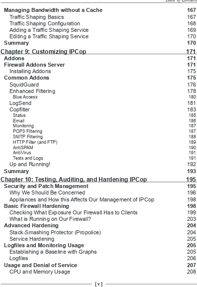
As an example of how NAT is used in practice, consider the following hypothetical scenario:
Consider the diagram above—a fictional ISP and four of its customers. Each
customer is allocated one IP address by the ISP, assigned to the computer or device directly attached to the connection provided by the ISP.
Customer A is a medium-sized solicitors firm—Customer A has a firewall based on
IPCop, several servers, and several clients in its private network segment. It uses the
10.0.1.0/24 (class C) subnet for its internal clients, but its external IP is actually used
by several dozen computers.
Customer B is a home user—customer B has only one computer, a laptop, which is directly attached to the ISP's internet connection. Customer B's external IP is used by one computer, and has no NAT and no private internal network.
Customer C is a larger manufacturing company—customer C has a high-end firewall
attached to its internet connection, and a large number of diverse devices in its
directly behind its firewall, and has a phone system, clients, server systems, and a
midrange mainframe system in its internal network.
Customer D is a home with several computers for members of the family, and a tablet PC—they have a handful of clients attached to a wireless network provided
by an all-in-one switch/router/firewall device (possibly the Linksys WAP54G
mentioned earlier) purchased at a local computer store.
Just four IP addresses actually represent hundreds of clients on the Internet—through
clever use of technology, clients using Internet Service Providers to provide access to the Internet reduce IP wastage by not allocating an IP address for every host.
If your computer exists as a host on a network on which the default gateway is performing Network Address Translation, and you visit a website, your computer will initiate a connection to port 80 on the web server you are connecting to, your computer will send a packet of data from the IP address it has (in the case of NAT, a private address like 192.168.1.23) to the destination. The destination will, in the case of a website on the Internet, be an internet-routable IP address such as 72.14.207.99 (one of Google's IP addresses).
If your gateway simply forwarded this packet to Google, it would be unlikely to get
there in the first place, as a router between your computer and Google would almost certainly be configured to 'drop' packets from addresses like the 192.168.0.0/16
address range, which are not valid for internet communications. Instead, therefore, your router rewrites the packet before forwarding it, and swaps the 192.168.1.23 for the external address of your router, given to you temporarily by your ISP.
When replies come back from the host at the other end, the router, having made
a note of the translation process, consults a table in memory, establishes based on the sequence number of the connection that 192.168.1.23 was the originating host, and rewrites the packet back again. Effectively, your clients are masquerading as the device attached to the Internet (or it is masquerading as them), and indeed,
'masquerading' is the technical term used for NAT in the iptables/netfilter firewalling components in Linux. Although the NAT process breaks some more
complicated protocols, it is an extremely effective way of having many hundreds or thousands of devices online behind one internet-routable (public) IP address.
For the clients, the setup appears as if their address range existed as a normal, routed segment of the Internet, whereas in actual fact, the 'default gateway' is performing Network Address Translation. In this manner, the worldwide shortage of IP
addresses is alleviated at the expense of some convenience. Small and home office
Private Address Ranges
These 'private' IP address ranges are set out in RFC 1918 (http://www.rfc-archive.org/getrfc. php?rfc=1918). RFCs, or Requests For Comment, while
not technical standards, are "technical and organizational notes about the Internet (originally the ARPANET), beginning in 1969. Memos in the RFC series discuss many aspects of computer networking, including protocols, procedures, programs, and concepts, as well as meeting notes, opinions, and sometimes humor." (http://www.rfc-editor.org/, front page, November 20, 2005). For protocols, standards, and
convention, they make an excellent first line of reference,
although (often depending upon the authors and intended audience) they are usually fairly technical.
The most recognizable of the private IP ranges is probably the 192.168.0.0/16 range,
which constitutes 255 class C 'subnets', of which the two most commonly used
are the 192.168.0.1/24 and the 192.168.1.1/24 subnets. This address range is very
frequently used as the default private address range for Small Office Home Office (SOHO) routers. There are also two other private address ranges for these purposes,
the 10.0.0.0/8 and 172.16.0.0/12 ranges.
Combined Role Devices
As a result of NAT, devices at the border of Small Office Home Office Networks,
therefore, are almost always combined-role, and although typically marketed as
router/firewalls or simply routers, often perform all of the following roles: Router (performing Network Address Translation)
Firewall DHCP server
Caching / Resolving DNS server
Intrusion Detection
VPN/IPSec server
Due to the complex nature of some of these tasks, it is often the case that the
'embedded' combined devices are difficult to configure and interoperating some
of the more complex functions (such as IPSec and File Serving) with other devices
(such as an IPSec/VPN device from another vendor) can be very difficult. Although
the price and size of these devices makes them a very attractive prospect for smaller networks, networks requiring some of the more advanced functionality should look at them quite carefully and evaluate whether or not, economically and technically, they will meet their needs.
When combined roles are required, larger, more fully designed solutions (such as a
firewall appliance from Borderware, Checkpoint, Cisco, et al.) or commercial piece of software (such as Microsoft's ISA server) often do the job more effectively and in a manner more configurable and interoperable than their smaller, cheaper SOHO
cousins. Obviously, we believe that not only does IPCop do a better job at the tasks
it is intended for than embedded devices, but than some of the commercial firewall
and gateway packages as well!
Traffic Filtering
Knowing what firewalls are intended to do and why their function is important to
us, it is now necessary to explore, briefly, how it is that firewalls accomplish the
broad purpose we've assigned for them.
Personal Firewalls
Personal firewalls have become increasingly common in the last five years. With the
inclusion of personal firewalling technology in Windows XP Service Pack 2 (and augmented technology in the upcoming Windows Vista), as well as firewalling
stacks in the OSX and Linux operating systems, it is now a fairly normal occurrence
for workstations and desktops to be running firewalling software.
Generally, this comes in one of two forms—either firewalling software built into the operating system (as in the case of OSX, Linux, and XP's Windows Firewall), or one of the many third-party firewalls from software vendors who write such software.
Two relatively well regarded examples of such packages are Agnitum's Outpost
package and ZoneLabs ZoneAlarm package.
Personal firewalling software cannot be a true firewall. As we have discussed earlier,
a firewall is a security boundary between one side of the firewall and another. By definition, a personal firewall must accept data onto a computer before making the
decision as to whether it is allowed to be there or not. Many forms of exploit involve
the misinterpretation of maliciously crafted data while parsing and evaluating
that data. Since a firewall is performing these tasks on the host it is supposed to
be protecting, there is no way in which it can effectively isolate the portions of the software that are doing the protecting from the portions of the software that are
being protected. Even for a smaller network, a personal firewall can never offer the degree of segregation that a network firewall provides.
Although personal firewalling software is relatively effective against inbound
(ingress) traffic, such software cannot offer protection against unauthorized outbound (or egress) traffic, since an application generating such traffic on the workstation will typically have some degree of access to the firewall's internals. If
the logged on user is an administrator of the workstation (or if there exists a security
flaw in the operating system allowing a non-administrative application to gain system or administrative privileges), it is quite possible to circumvent software/ personal firewalls using the operating system (http://www.vigilantminds.com/ files/defeating_windows_personal_firewalls.pdf) in a way that simply isn't
possible with a firewall distinct from the client itself.
Many personal firewall packages, such as ZoneAlarm, step beyond the services offered solely by a packet filtering firewall, and serve as a Host-based Intrusion
Detection System (HIDS) or Host-based Intrusion Prevention System (HIPS). These systems actively monitor, and in the case of a HIPS, prevent, alterations to the operating system and its components. Such functions cannot be provided
by a network firewall such as IPCop for obvious reasons, but the same criticisms
apply to a HIPS as to a Personal Firewall—ultimately, if the host it is running on is compromised, the accuracy of the Intrusion Prevention System is compromised also.
Recent developments in security include rootkit software, which is capable of providing a 'backdoor' into a host operating system using virtualization software
(such as VMware) and hardware-based virtualization support (such as that in AMD and Intel's newest processors). Such software, like VMware and Virtual PC
themselves, literally acts as a container (or hypervisor) for the OS running inside it, the consequence of which is that such backdoors literally exist outside the OS that installed them. In light of these concepts being demonstrated publicly, the role of
host-based firewall and IPS software is redoubled—part of a security solution, but
not a 'killer app'. Fundamentally, what we can take from this that is for sure is that different packages have different strengths, and we shouldn't ever rely on one in particular.
Although an important part of an overall stance on security, not all firewalls are created equal, and a personal firewall should never be considered to be a substitute for well-designed, well-maintained perimeter and segment firewalling as part of a
Stateless Packet Filtering
'Packet filtering' is a term generally used to describe a firewall, acting at the network layer, which decides where data should go based on criteria from the data packet. Generally, this will include the source and destination ports and source and destination addresses—so, for instance, an organization may allow connections to its remote access server from a business partner's IP address range but not from the Internet in general. Other criteria may include the time of day at which the connection is made.
Although fast and historically effective, 'stateless' packet filters operate solely at the network layer and provide no inspection of data traveling through them at all—a
stateless packet filter configured to allow traffic from the Internet to port 80 in an organization's DMZ will allow such traffic, irrespective of what the data going to
port 80 is, and more importantly whether or not that data is actually part of an established connection.
Stateful Packet Filtering
A packet filter that is stateful understands the state of a TCP connection that is in
progress through it. When a TCP Connection is set up a very specific process known
as a 'three-way handshake' takes place between the source and the target hosts.
This is a very basic, simplistic explanation of stateful firewalling—it would be out of scope for this text to cover the entire topic of stateful firewalling (there are other
resources such as http://en.wikipedia.org/wiki/Stateful_inspection that cover this), but a basic explanation of the topic is useful:
Firstly, the client in the connection issues a TCP SYN packet to the destination. For the firewall, this is considered a 'new' connection, and at this point the firewall will
allocate memory to track the status of the connection as it progresses.
Secondly, the server—if the connection proceeds as expected—replies by sending back a packet with the correct sequence number, source, and destination ports, with
both SYN and ACK flags set.
Thirdly, the client, upon receiving the SYN ACK packet, returns a third packet with solely the ACK packet set. Frequently, this packet will also contain some of the first bits of data pertaining to the connection in it. At this point, the firewall considers the
connection to be 'established', and will allow data associated with this connection
(that is to say, data to and from the source/destination addresses, going to and
from the correct ports, with the correct sequence number) to freely pass through