Engineering Design
of A Gang Drilling Machine Equipped
with Jig and Fixtures to Make
A Prototype Machine in Birdcage Production
Eddy Widiyono, Winarto, Rivai Wardhani, and Liza Rusdiyana1
Abstract
—
This paper is dealing with the engineering design of a gang drilling machine with jig & fixtures to make a prototype machine. This effort has been done in order to solve the problem which aroused in small business enterprises producing birdcages. The problem was how to minimize the production time in making a lot of holes that have same distance and straightness. Hopefully, the prototype machine can help the small business enterprises to increase their production rate.The design engineering process has been carried out by variant approximation on dowel pin modular fixtures in order to simplify fixtures design. CAD CAM software has also been used as fixtures synthesized method including geometric analysis and three dimensional fixtures assembling. The resulting prototype machine can be well operated and based on the running test, it can be concluded that the greater the motor rotation the greater the power needed. As for teak wood, at 250 rpm motor rotation the power needed is 26.5 watt, and at 400 rpm the motor needs power of 43.6 watt while at 600 rpm the motor needs power of 600 watt. The power consumption is also depends on the type of material, the better the mechanical properties of the materials, the higher the power consumption. For cast iron, the 400 rpm motor rotation needs power as high as 569.7 watt. This prototype of gang drilling machine needs power of 350 watt to make five holes on teak wood while ordinary drilling machine needs total power of 1350 watt.Keywords
—
birdcage, fixtures, gang drill, jig, small businessAbstrak
—
Makalah ini membahas mengenai rekayasa prototipe gang drill dengan jig & fixturenya, untuk mengatasi salah satu permasalahan yang ada di UKM sangkar burung, di dalam proses pembuatan sangkar burung, perlu adanya penerapan teknologi tepat guna yang berupa satu unit mesin gang drill dengan jig & fixturenya yang mampu membuat lubang yang banyak, dengan jarak dan kelurusan yang sama secara cepat, sehingga produksi UKM sangkar burung dapat ditingkatkan. Pengembangan metode perancangan dan modifikasi fixture dengan pendekatan varian pada modular fixture berbasis dowel pin juga bisa memudahkan dalam perancangan fixture. Sofware CAD CAM dapat digunakan sebagai metode sintesis fixture termasuk analisis geometri, perencanaan dan perakitan fixture secara 3 dimensi dengan cepat. Mesin gang drill dengan jig & fixture, hasil rekayasa dapat bekerja dengan baik dan berdasarkan hasil pengujian makin tinggi putaran motor, maka makin besar daya yang dibutuhkan, untuk bahan kayu jati pada putaran 250 rpm, daya yang dibutuhkan sebesar 26,5 W dan pada putaran 600 rpm daya yang dibutuhkan 600 W. Juga kebutuhan daya pada proses drilling, juga tergantung jenis bahan yang akan diporoses, makin tinggi harga sifat mekanik bahan, maka kebutuhan daya untuk proses drilling makin besar. Kebutuhan daya untuk proses drilling pada bahan kayu jati dengan putaran motor 400 rpm sebesar 43,6 W, sedangkan untuk bahan besi tuang dengan putaran motor 400 rpm sebesar 569,7 W. Kebutuhan waktu dan daya dalam pembuatan 5 lubang dengan bahan kayu jati menggunakan mesin gang drill 1 motor 5 pahat jauh lebih rendah, bila dibanding dengan drill 1 motor 1 pahat sebesar 350 W dan 1350 W. Hal ini mesin gang drill 1 motor 5 pahat menjadikan produktivitas UKM produk sangkar burung akan meningkat.Kata Kunci
—
sangkar burung, fixture, gang drill, jig, industri kecilI.INTRODUCTION5
he management of fixtures system in machining remain relatively stagnant especially the progress of technology development. This condition governs to the needs of scientifically-based management of model formalization which can give significant contribution to the development of fixture systems [1].
The development of design method and fixtures modification using variant approximation based on dowel pin modular fixtures can also make fixtures design easier [2].
Eddy Widiyono, Winarto, Rivai Wardhani, Liza Rusdiyana are with Department of Mechanical Engineering D.3 Program, Faculty of Industrial Technology, Institut Teknologi Sepuluh Nopember, Surabaya, 60111, Indonesia. Email: [email protected], [email protected], [email protected], [email protected].
CAD/CAM/CAE/CAT softwares can be used as fixture synthesized method including geometric analysis, design and assembling of fixture in three dimensional mode [3-4].
Expert system has been developed for designing the fixtures which can be used as a basic guide in designing and assembling the appropriate fixtures [5].
When assembling fixture in a machining process, the workpiece position, tool movement, pin/locator flexibility have to be considered so that the elements of jig and fixture will be interchangeable and reusable [6].
Designing and assembling of jig and fixture can be carried out using finite element method, then simulated by the ANSYS software [7]. Carbon fiber composite has been used as the material of jig and fixture in car assembling [8].
that produce birdcage to solve their problem. Their problem was how to drill many holes in one step, how to maintain the same distance between holes, and how to maintain the holes straightness. In the past, the drilling process was done one by one for each hole so that the drilling process was very exhausted [9].
This gang drillig machine is equipped with jig and fixtures specially in the type of drilling jig, which control the relationship between work piece and cutting tool. Meanwhile, the fixtures in this machine is used as the clamping elements for gripping the work piece.
To realize this engineering process, it would require the calculation of the main components such as shaft, gear, bearing and spring and pin.
The following equation is used for the shaft calculation [10-12]:
D > (1)
After obtaining the shaft diameters and materials used, so one can determine the shaft to get the long life usage.
Gears are used to transmits power and rotational motion between two shafts arranged parallel. The type of the gear used in this design is the straight spur gears,
The number of teeth (Nt) can be calculated as follows,
(3) When two gears are in mesh, the distance between the center of the two gears (C1), is equal to one half the sum
of their pich diameters. In equation form [11],
(4) Before getting a dynamic load, it is necessary to get the
peripheral speed (vp),
(8)
The dynamic effect on gear teeth, due to such factors as inaccurately cut teeth, improper tooth spacing, improper mounting, deflection due to elasticity of the gears and shaft, and irregular load requirements must be taken in account in this preliminary design stage. The dynamic load (Fd) can be calculated by,
(9) for 0 vp 2000ft/min So that the width of the teeth (b) of gears can be obtained by the following equation,
(10)
(11)
In order to prevent the gear damage, hence one shall have to know the size of the working load, that is :
(12)
(13)
and,
(14)
Bearings should have also been chosen appropriately by determining the working load and life of the bearings [10, 13]. effect of the shear and the compressive stress needs to be considered [13].
Review to the shear stress
min
Review to the compressive stress,
L function of a spring is to absorb shock and to support the weight of the machine. To determine the dimensions of the corresponding spring, the spring correction factors diagramin Figure 2can be used.
The number of coil springs (Nt), deflection, then spring is in static conditions has received a static force. If the specified used shear modulus G = 11.5 x 10⁶ , then the static force that resulted in large initial deflection to:
Pmin=Ptatis= (26)
Furthermore, from load fluctuations can be determined the average load (Pmean = Pm) and load amplitude (Prange = Pr) as follows, amplitude. Shear stress amplitude value,
25
Materials used in this study, in determining the speed of drilling and power requirements are teak, aluminum, brass and cast iron that have mechanical properties, such as Table 1.
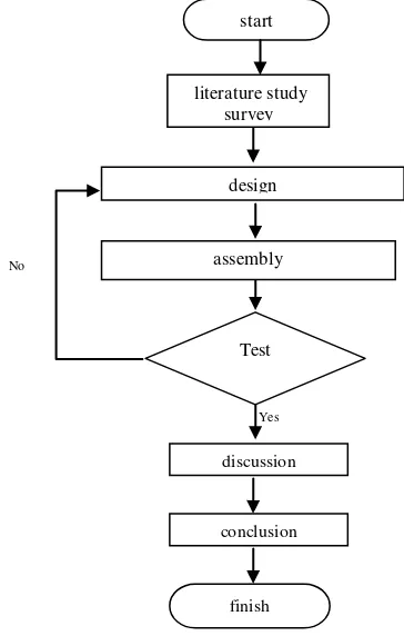
B. Research Flowchart
In order to design the prototype of gang drill equipped with jig & fixture, it is recessary to have some steps as, shown in the flow chart in Figure 4.
C. Examination
In order to get a gang drill machine which is able to work properly, the testing by variying the material and rotational speed are conducted. Therefore, the power requirements for fine drilling chisels work
simultaneously are known. Five rotational speed (150 rpm, 250 rpm, 400 rpm and 1450 rpm) are used in the experiments while the tested materials are teak wood, aluminum, brass and cast iron. Every drilling process for certain material and rotational speed is carried out with 5 (five) times iteration.
To find out, how much gang drilling machine can be useful for small business in order to improving productivity, verification of drilling speed and power requirements are performed for single chisel drilling machine with a single motor gang drill. Therefore, time difference and resources required in the drilling process between them can be known. Tests is carried out by varying the number of chisell drill (1 pieces, 2 pieces, 3 pieces, 4 pieces and 5 pieces) and materials (teak wood, aluminum, brass and cast iron). Each test is iterated five time.
III.RESULTS AND DISCUSSION
Based on the calculations, the countershaft and the driven shaft have the dimension, which are listed in Figure 5 and 6, respectively. Where as the specifications are given in Table 2.
Futhermore, the straight gears are used to transmit power and rotary motion between the two shaft which are arranged parallely as shown in Figure 7 and 8. The specification of the gears are given in Table 3.
As for bearings, roller bearings (ball bearings, single row- deep groove) are chosen with the specification in Table 4. The Pin and spring are specified in Table 5 and 6 respectifely.
Based on the results of testing by varying the rotational speed and test materials, the power requirements for 5 consume the power of 26.5 W and 600 W, respectively. Motor rotation speed has significant effect to cutting speed, force and torque. The greater the motor rotation, the higher the cutting speed. How ever, the power demand also increase of force and torque.
By observing Figure 9, it can be known that there are some differences on the power requirements for different materials. Cast iron consumens the higher while teak wood pays the lower one for the some motor rotation due to the different of mechanical properties.
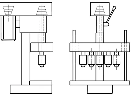
The differences between the two drill machines lies on the construction design. The first type is the gang drill machine with one motor and five chisel. A single main shaft with four driven-shaft and four link-gear are used as the power transmission system. On the other hand, the scond type, ehich is the original machine used by small business, uses a motor with single chisel and the driven-shaft only.
Therefore, gang drill machine has increased productivity and efficience of birdcage manufacturer.
IV.CONCLUSION
1. Prototype of gang drill equipped with a jig & fixture, has been made and tested. Testing should that the machine can be functionalized properly.
2. The higher the motor rotation, the greater of power needed. For teak wood at 250 rpm requires power of 26.5 W. At the higher rotaton of 600 rpm, the greather power of 600 W consumed.
3. Power requirements of the drilling process, depends on the mechinal properties of materials. Materials with higher mechanical properties consume more
power in order to accomplish the process than lower ones. For rotation at 400 rpm, teak wood need power of 43.6 W only while cast iron spending power of 569.7 W
4. Power requirements to make 5 holes for teak wood using gang drill machine with 1 motor and 5 chisels is lower than the ordinary/original machine 1 motor and 1 chisel.
5. The drilling time to make 5 holes using gang drill machine is shorter than the ordinary machine.
ACKNOWLEDGEMENT
Directorate General of Higher Education, Ministry of National Education.
Figure 1. The center distance (C1)
Figure 2. The spring correction factors diagram [14]
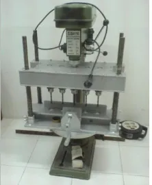
Figure 3. Prototype of gang drilling machine is equipped with jig and fixture
C
d
2Figure 4. Research methodology flowchart
Figure 5. Countershaft Figure 6. Driven shaft
Figure 7. Pinion Figure 8. Gear
start
literature study survey
design
assembly
Test
discussion
conclusion
Figure 9. Diagram of energy requirement of gang drilling machine with materials and rotation variation
Figure 10. Diagram of comparison energy requirement of gangway machine drill with one motor and machine drill with one chisel (single
drill)
Figure 11. Gang Drilling Machine [9]
Figure 12. Diagram of comparative length of time drilling, drill machine with a gang drill machine with one motor and one chisel (single drill)
TABLE 1.
MECHANICAL PROPERTIES OF MATERIAL TEST
Material Test Tensile Stress
Elongation
Tensile MPa Yield Mpa %
Teak 50 40 0%
Aluminium 70 20 60%
Brass 200 70 4%
Cast Iron 380 120 1%
TABLE 2. SHAFT SPECIFICATION
Material
Counter shaft Shaft driven Carbon Steel AISI
1137
TABLE 3. SPECIFICATION OF GEARS
Pinion Gear
Material gear steel number 350
gear steel number 325
Diameter 36.75 mm 49 mm
Number of teeth
21 pieces 28 pieces
Width of teeth 24 mm 21 mm
TABLE 4. BEARING SPECIFICATION
Type of bearing Type of roller
Inside diameter (d) 20 mm
Outside diameter (D) 47 mm
Width 12 mm
Co 715 lb
C 1710 lb
TABLE 5. PIN SPECIFICATION
Type of pin Square standart key Material malleable iron grade 32510
Length (L) 0.8 in
Width (W) 0.25 in
High (H) 0.25 in
TABLE 6. SRING SPESIFICATION
Spring material ASTM class 20 Spring free length (Lf) Malleable iron grade
32510
Inner diameter spring (D) 0.25 in Outer diameter spring (Do) 0.25 in Wire diameter (d) 0.8 in
TABLE 7.
ENERGY REQUIREMENT OF GANG DRILLING MACHINE WITH MATERIALS AND ROTATION VARIATION Rotation Teak wood (Tw) Aluminium (Al) Brass (Brs) Cast iron (Ci)
150 15.6 90.8 95.1 212.8
250 26.5 122.0 259.0 355.2
400 43.6 144.4 355.7 569.7
1450 190.1 417.9 758.8 896.9
REFERENCES
[1] L. A. Consalter and Boehs, “An Approach to Fixture Systems Management in Machining Processes,” Journal of the Braz. Soc. Of Mech. Sci. & Eng. vol.XXVI, no.2, p. 145-152, 2004.
[2] T. M. Nugroho and A. Ma’ruf, ”Pengembangan Metode Perancangan dan Modifikasi Fixture dengan Pendekatan Varian Pada Modular Fixture Berbasis Dowel-Pin,” Jurnal Teknik Gelagar, vol.19, no.01. pp.59-65, 2008.
[3] D. T. Pham, S. Z Su., M. Z. Li., and C. G. Liu, Digital Dieless Tooling Technology for Manufacturing 3D Panel Using Multi-Point Forming Methodology, Manufacturing Engineering Centre, Cardiff, CF 24 3AA, UK, 2008.
[4] P. Qingjin and K. Xiumei, Fixture Feasility: Methods and Techniques for Fixture Planning, Computer-Aided Desain & Applications, vol.5, no.1-4, pp. 423-433, 2008.
[5] D. Vukelic and J. Hodolic, “Machining Fixture Design Via Expert System,” Adeko, Machine Design Journals, ISSN 1821-1259, 2009.
[6] M. Krsulja, B .Barisic, and J. Kudlacek, Assembly Setup For Modular Fixture Machining Process, Advanced Engineering 3, ISSN 1846-5900, 2009.
[7] S. Siwadamrongpong and U. Ongarjwutichai, “Simulation and Design of Jig for Bus’s Chassis Production,” International Journal of Mechanics, vol.4, issue 4, pp. 87-93, 2010.
[8] E. Leondardt, J. Waltman, and V. Iyer, “Composite Hood Jig for Automotive Assembly Process”, in Proceeding of the IJME-INTERTECH Conference, Session IT 301-042, 2006.
[9] Winarto and E. Widiyono, “Penerapan Teknologi Tepat Guna, Prototype Mesin Gang Drill Dengan Jig & Fixture, Dalam Peningkatan Produksi Dan Kualitas Industri Kecil Sangkar Burung, Guna Memenuhi Pangsa Pasar Luar Jawa,” Laporan Program Voucher Dikti 06/07, 2007.
[10] J. A. Collins, Mechanical Design of Machine Elements and Machines, Jon Wiley and Sons Inc., New York, 2003.
[11] D. Aaron, D. Walter, J. Michels, and E.W. Charles. Machine Design Theory and Practice, Macmillan Publishing Co, Inc, New York, 1975.
[12] R. C. Hibbeler, Engineering Mechanics: Dynamics : Upper Saddle River, Prentice-Hall, 2001.
[13] D. B. Margitu, Mechanical Engineer’s Handbook, Academic Press, San Diego, 2001.