P H Y S I C S
Third edition
K e n n e t h S. K r a n e
D E P A R T M E N T O F P H Y S I C S
O R E G O N S T A T E U N I V E R S I T Y
THE SPECIAL THEORY OF
RELATIVITY
Einstein’s special theory of relativity and Planck’s quantum theory burst forth on the physics scene almost simultaneously during the first decade of the 20th century. Both theories caused profound changes in the way we view our universe at its most fundamental level.
In this chapter we study the special theory of relativity.∗ This theory has a completely undeserved reputation as being so exotic that few people can understand it. On the contrary, special relativity is basically a system of kinematics and dynamics, based on a set of postulates that are different from those of classical physics. The resulting formalism is not much more complicated than Newton’s laws, but it does lead to several predictions that seem to go against our common sense. Even so, the special theory of relativity has been carefully and thoroughly tested by experiment and found to be correct in all its predictions.
We first review the classical relativity of Galileo and Newton, and then we show why Einstein proposed to replace it. We then discuss the mathematical aspects of special relativity, the predictions of the theory, and finally the experimental tests.
2.1 CLASSICAL RELATIVITY
A “theory of relativity” is in effect a way for observers in different frames of reference to compare the results of their observations. For example, consider an observer in a car parked by a highway near a large rock. To this observer, the rock is at rest. Another observer, who is moving along the highway in a car, sees the rock rush past as the car drives by. To this observer, the rock appears to be moving. A theory of relativity provides the conceptual framework and mathematical tools that enable the two observers to transform a statement such as “rock is at rest” in one frame of reference to the statement “rock is in motion” in another frame of reference. More generally, relativity gives a means for expressing the laws of physics in different frames of reference.
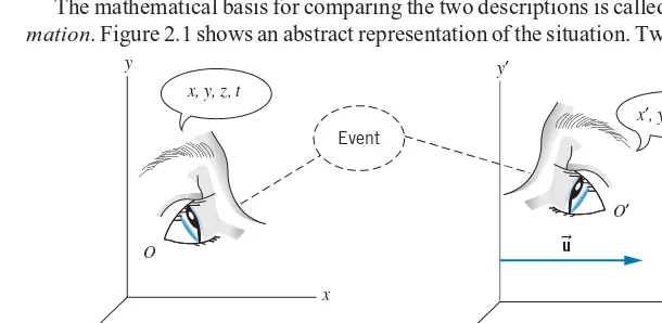
The mathematical basis for comparing the two descriptions is called a transfor-mation. Figure 2.1 shows an abstract representation of the situation. Two observers
z
x y
x, y, z, t
x′, y′, z′, t′ Event
u
z′
x′
y′
O′
O
FIGURE 2.1 Two observersOandO′observe the same event.O′moves relative toOwith a constant velocity
u.
OandO′are each at rest in their own frames of reference but move relative to one another with constant velocity
u. (OandO′refer both to the observers and their reference frames or coordinate systems.) They observe the sameevent, which happens at a particular point in space and a particular time, such as a collision between two particles. According to O, the space and time coordinates of the event arex, y, z, t,while according toO′the coordinates of thesame eventarex′, y′, z′, t′. The two observers use calibrated meter sticks and synchronized clocks, so any differences between the coordinates of the two events are due to their different frames of reference and not to the measuring process. We simplify the discussion by assuming that the relative velocity
ualways lies along the common
xx′direction, as shown in Figure 2.1, and we let
urepresent the velocity ofO′as measured byO(and thusO′would measure velocity−
uforO).
In this discussion we make a particular choice of the kind of reference frames inhabited byOand O′. We assume that each observer has the capacity to test Newton’s laws and finds them to hold in that frame of reference. For example, each observer finds that an object at rest or moving with a constant velocity remains in that state unless acted upon by an external force (Newton’s first law, the law of inertia). Such frames of reference are calledinertial frames. An observer in interstellar space floating in a nonrotating rocket with the engines off would be in an inertial frame of reference. An observer at rest on the surface of the Earth is
notin an inertial frame, because the Earth is rotating about its axis and orbiting about the Sun; however, the accelerations associated with those motions are so small that we can usually regard our reference frame as approximately inertial. (The noninertial reference frame at the Earth’s surface does produce important and often spectacular effects, such as the circulation of air around centers of high or low pressure.) An observer in an accelerating car, a rotating merry-go-round, or a descending roller coaster isnotin an inertial frame of reference!
We now derive the classical or Galilean transformation that relates the coordinatesx, y, z, ttox′, y′, z′, t′. We assume as a postulate of classical physics thatt=t′, that is, time is the same for all observers. We also assume for simplicity that the coordinate systems are chosen so that their origins coincide att=0. Consider an object inO′at the coordinatesx′, y′, z′(Figure 2.2). According toO, theyandzcoordinates are the same as those inO′. Along thexdirection,Owould observe the object at x=x′+ut. We therefore have the Galilean coordinate transformation
x′=x−ut y′=y z′=z (2.1) To find the velocities of the object as observed byOandO′, we take the derivatives of these expressions with respect to t′ on the left and with respect to t on the right (which we can do because we have assumedt′=t). This gives theGalilean velocity transformation
z
O x
x ut y
z′
z′
O′
P
x′
y′
x′
y′ u
FIGURE 2.2 An object or event at
pointPis at coordinatesx′,y′,z′with respect toO′. Thex coordinate mea-sured byOisx=x′+ut. Theyandz
coordinates inOare the same as those inO′.
v′x=vx−u vy′ =vy v′z=vz (2.2)
In a similar fashion, we can take the derivatives of Eq. 2.2 with respect to time and obtain relationships between the accelerations
a′x=ax a′y=ay a′z=az (2.3) Equation 2.3 shows again that Newton’s laws hold for both observers. As long as
Example 2.1
Two cars are traveling at constant speed along a road in the same direction. Car A moves at 60 km/h and car B moves at 40 km/h, each measured relative to an observer on the ground (Figure 2.3a). What is the speed of car A relative to car B?
Solution
LetObe the observer on the ground, who observes car A to move atvx=60 km/h. Assume O′ to be moving with car B atu=40 km/h. Then
v′x=vx−u=60 km/h−40 km/h =20 km/h
Figure 2.3bshows the situation as observed byO′.
O′
An airplane is flying due east relative to still air at a speed of 320 km/h. There is a 65 km/h wind blowing toward the north, as measured by an observer on the ground. What is the velocity of the plane measured by the ground observer?
Solution
Let O be the observer on the ground, and let O′ be an observer who is moving with the wind, for example a balloonist (Figure 2.4). Thenu=65 km/h, and (because our equations are set up with
u in thexx′ direction) we must choose the xx′ direction to be to the north. In this case we know the velocity with respect toO′; taking theydirection to the east, we havev′x=0 andv′y=320 km/h. Using Eq. 2.2 we obtain
vx=v′x+u=0+65 km/h=65 km/h
vy=v′y=320 km/h
Relative to the ground, the plane flies in a direction determined byφ=tan−1(65 km/h)/(320 km/h)=11.5◦,
FIGURE 2.4 Example 2.2. As observed by Oat rest on the ground, the balloon drifts north with the wind, while the plane flies north of east.
Example 2.3
A swimmer capable of swimming at a speedcin still water is swimming in a stream in which the current isu(which we assume to be less thanc). Suppose the swimmer swims upstream a distanceLand then returns downstream to the starting point. Find the time necessary to make the round trip, and compare it with the time to swim across the stream a distanceLand return.
Solution
Let the frame of reference of O be the ground and the frame of reference of O′ be the water, moving at speed u (Figure 2.5a). The swimmer always moves at speed c relative to the water, and thus v′x= −c for the
upstream swim. (Remember that u always defines the
so vx=v′x+u=u−c. (As expected, the velocity
rel-ative to the ground has magnitude smaller than c; it is also negative, since the swimmer is swimming in the negative x direction, so |vx| =c−u.) Therefore, To swim directly across the stream, the swimmer’s efforts must be directed somewhat upstream to counter the effect of the current (Figure 2.5b). That is, in the frame of ref-erence ofOwe would like to havevx=0, which requires
v′x= −u according to Eq. 2.2. Since the speed relative to Notice the differencein formbetween this result and the result for the upstream-downstream swim, Eq. 2.4.
O
FIGURE 2.5 Example 2.3. The motion of a swimmer as seen
by observerOat rest on the bank of the stream. ObserverO′
moves with the stream at speedu.
2.2 THE MICHELSON-MORLEY EXPERIMENT
We have seen how Newton’s laws remain valid with respect to a Galilean transfor-mation that relates the description of the motion of an object in one reference frame to that in another reference frame. It is then interesting to ask whether the same transformation rules apply to the motion of a light beam. According to the Galilean transformation, a light beam moving relative to observerO′in thex′direction at speedc=299,792,458 m/s would have a speed ofc+urelative toO. Direct high-precision measurements of the speed of light beams have become possible in recent years (as we discuss later in this chapter), but in the 19th century it was necessary to devise a more indirect measurement of the speed of light according to different observers in relative motion.
Suppose the swimmer in Example 2.3 is replaced by a light beam. Observer
O′ is in a frame of reference in which the speed of light isc, and the frame of reference of observerO′is in motion relative to observerO. What is the speed of light as measured by observerO? If the Galilean transformation is correct, we should expect to see a difference between the speed of the light beam according toOandO′and therefore a time difference between the upstream-downstream and cross-stream times, as in Example 2.3.
Physicists in the 19th century postulated just such a situation— a preferred frame of reference in which the speed of light has the precise value ofcand other frames in relative motion in which the speed of light would differ, according to the Galilean transformation. The preferred frame, like that of observerO′in Example 2.3, is one that is at rest with respect to the medium in which light propagates atc(like the water of that example). What is the medium of propagation for light waves? It was inconceivable to physicists of the 19th century that a wave disturbance could propagate without a medium (consider mechanical waves such as sound or seismic waves, for example, which propagate due to mechanical forces in the medium). They postulated the existence of an invisible, massless medium, called theether,
which filled all space, was undetectable by any mechanical means, and existed solely for the propagation of light waves. It seemed reasonable then to obtain evidence for the ether by measuring the velocity of the Earth moving through the ether. This could be done in the geometry of Figure 2.5 by measuring the difference between the upstream-downstream and cross-stream times for a light wave. The calculation based on Galilean relativity would then give the relative velocityu
betweenO(in the Earth’s frame of reference) and the ether.
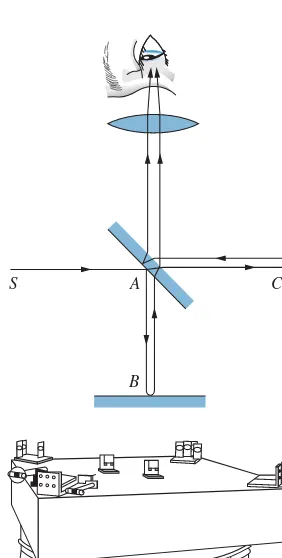
The first detailed and precise search for the preferred frame was performed in 1887 by the American physicist Albert A. Michelson and his associate E. W. Morley. Their apparatus consisted of a specially designed Michelson interferometer, illustrated in Figure 2.6. A monochromatic beam of light is split in two; the two beams travel different paths and are then recombined. Any phase difference between the combining beams causes bright and dark bands or “fringes” to appear, corresponding, respectively, to constructive and destructive interference, as shown in Figure 2.7.
S A
B
C
FIGURE 2.6 (Top) Beam diagram of Michelson interferometer. Light from sourceSis split atAby the half-silvered mirror; one part is reflected by the mirror atBand the other is reflected at C. The beams are then recom-bined for observation of the interfer-ence. (Bottom) Michelson’s appara-tus. To improve sensitivity, the beams were reflected to travel each leg of the apparatus eight times, rather than just twice. To reduce vibrations from the surroundings, the interferometer was mounted on a 1.5-m square stone slab floating in a pool of mercury.
There are two contributions to the phase difference between the beams. The first contribution comes from the path differenceAB−AC; one of the beams may travel a longer distance. The second contribution, which would still be present even if the path lengths were equal, comes from the time difference between the upstream-downstream and cross-stream paths (as in Example 2.3) and indicates the motion of the Earth through the ether. Michelson and Morley used a clever method to isolate this second contribution—they rotated the entire apparatus by 90◦! The rotation doesn’t change the first contribution to the phase difference (because the lengths AB and AC don’t change), but the second contribution changes sign, because what was an upstream-downstream path before the rotation becomes a cross-stream path after the rotation. As the apparatus is rotated through 90◦, the fringes should change from bright to dark and back again as the phase difference changes. Each change from bright to dark represents a phase change of 180◦(a half cycle), which corresponds to a time difference of a half period (about 10−15s for visible light). Counting the number of fringe changes thus gives a measure of the time difference between the paths, which in turn gives the relative velocityu. (See Problem 3.)
six months later (when the Earth would be moving in its orbit in the opposite direction) the cancellation should not occur. When they repeated the experiment six months later, they again obtained a null result. In no experiment were Michelson and Morley able to detect the motion of the Earth through the ether.
FIGURE 2.7 Interference fringes as
observed with the Michelson inter-ferometer of Figure 2.6. When the path lengthACAchanges by one-half wave-length relative toABA, all light areas turn dark and all dark areas turn light. In summary, we have seen that there is a direct chain of reasoning that leads
from Galileo’s principle of inertia, through Newton’s laws with their implicit assumptions about space and time, ending with the failure of the Michelson-Morley experiment to observe the motion of the Earth relative to the ether. Although several explanations were offered for the unobservability of the ether and the corresponding failure of the upstream-downstream and cross-stream velocities to add in the expected way, the most novel, revolutionary, and ultimately successful explanation is given by Einstein’s special theory of relativity, which requires a serious readjustment of our traditional concepts of space and time, and therefore alters some of the very foundations of physics.
2.3 EINSTEIN’S POSTULATES
Thespecial theory of relativityis based on two postulates proposed by Albert Einstein in 1905:
The principle of relativity:The laws of physics are the same in all inertial reference frames.
The principle of the constancy of the speed of light:The speed of light in free space has the same value c in all inertial reference frames.
The first postulate declares that the laws of physics are absolute, universal, and the same for all inertial observers. Laws that hold for one inertial observer cannot be violated foranyinertial observer.
Albert Einstein (1879–1955, Ger-many-United States). A gentle philoso-pher and pacifist, he was the intellectual leader of two generations of theoretical physicists and left his imprint on nearly every field of modern physics. The second postulate is more difficult to accept because it seems to go against
our “common sense,” which is based on the Galilean kinematics we observe in everyday experiences. Consider three observersA,B, andC. ObserverBis at rest, whileAandCmove away fromBin opposite directions each at a speed ofc/4.B
fires a light beam in the direction ofA. According to the Galilean transformation, if B measures a speed of c for the light beam, then A measures a speed of
c−c/4=3c/4, whileCmeasures a speed ofc+c/4=5c/4. Einstein’s second postulate, on the other hand, requires all three observers to measure the same speed ofcfor the light beam! This postulate immediately explains the failure of the Michelson-Morley experiment—the upstream-downstream and cross-stream speeds are identical (both are equal toc), so there is no phase difference between the two beams.
The two postulates also allow us to dispose of the ether hypothesis. The first postulate does not permit a preferred frame of reference (all inertial frames are equivalent), and the second postulate does not permit only a single frame of reference in which light moves at speedc, because light moves at speedcinall
2.4 CONSEQUENCES OF EINSTEIN’S POSTULATES
Among their many consequences, Einstein’s postulates require a new considera-tion of the fundamental nature of time and space. In this secconsidera-tion we discuss how the postulates affect measurements of time and length intervals by observers in different frames of reference.
L0
M
S
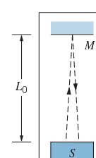
FIGURE 2.8 The clock ticks at
inter-vals t0 determined by the time for a light flash to travel the distance 2L0
from the light sourceS to the mirror
M and back to the source where it is detected. (We assume the emission and detection occur at the same loca-tion, so the beam travels perpendicular to the mirror).
The Relativity of Time
To demonstrate the relativity of time, we use the timing device illustrated in Figure 2.8. It consists of a flashing light source S that is a distanceL0 from a mirrorM. A flash of light from the source is reflected by the mirror, and when the light returns toSthe clock ticks and triggers another flash. The time interval between ticks is the distance 2L0(assuming the light travels perpendicular to the mirror) divided by the speedc:
t0=2L0/c (2.6) This is the time interval that is measured when the clock is at rest with respect to the observer.
We consider two observers:Ois at rest on the ground, andO′moves with speed
u. Each observer carries a timing device. Figure 2.9 shows a sequence of events that
Oobserves for the clock carried byO′. According toO, the flash is emitted when the clock ofO′is atA, reflected when it is atB, and detected atC. In this interval
t,Oobserves the clock to move forward a distance ofutfrom the point at which the flash was emitted, andOconcludes that the light beam travels a distance 2L, whereL=√L20+(ut/2)2, as shown in Figure 2.9. BecauseOobserves the light beam to travel at speedc(as required by Einstein’s second postulate) the time interval measured byOis
t= 2L
c =
2√L2
0+(ut/2)2
c (2.7)
Substituting forL0from Eq. 2.6 and solving Eq. 2.7 fort, we obtain
t= √ t0
1−u2/c2 (2.8)
L0 L
u ∆t
L A
O′
O
B
O′
C
O′ u
FIGURE 2.9 In the frame of reference ofO, the clock carried byO′moves with speed
According to Eq. 2.8, observerOmeasures a longer time interval thanO′measures. This is a general result of special relativity, which is known astime dilation. An observerO′is at rest relative to a device that produces a time intervalt0. For this observer, the beginning and end of the time interval occur at the same location, and so the intervalt0is known as theproper time. An observerO, relative to whomO′is in motion, measures a longer time intervaltfor the same device. The dilated time intervalt is always longer than the proper time intervalt0, no matter what the magnitude or direction of
u.
This is a real effect that applies not only to clocks based on light beams but also to time itself; all clocks run more slowly according to an observer in relative motion, biological clocks included. Even the growth, aging, and decay of living systems are slowed by the time dilation effect. However, note that under normal circumstances (u≪c), there is no measurable difference betweent andt0, so we don’t notice the effect in our everyday activities. Time dilation has been verified experimentally with decaying elementary particles as well as with precise atomic clocks carried aboard aircraft. Some experimental tests are discussed in the last section of this chapter.
Example 2.4
Muons are elementary particles with a (proper) life-time of 2.2 μs. They are produced with very high speeds in the upper atmosphere when cosmic rays (high-energy particles from space) collide with air molecules. Take the heightL0 of the atmosphere to be 100 km in the reference frame of the Earth, and find the minimum speed that enables the muons to survive the journey to the surface of the Earth.
Solution
The birth and decay of the muon can be considered as the “ticks” of a clock. In the frame of reference of the Earth (observerO) this clock is moving, and therefore its ticks are slowed by the time dilation effect. If the muon is moving at a speed that is close toc, the time necessary for it to travel from the top of the atmosphere to the surface of the Earth is
t=L0
c =
100 km
3.00 ×10⁸m/s=333μs
If the muon is to be observed at the surface of the Earth, it must live for at least 333 μs in the Earth’s frame of reference. In the muon’s frame of reference, the interval between its birth and decay is a proper time interval of 2.2μs. The time intervals are related by Eq. 2.8:
333μs=2.2μs 1−u2/c2
Solving, we find
u=0.999978c
If it were not for the time dilation effect, muons would not survive to reach the Earth’s surface. The observation of these muons is a direct verification of the time dilation effect of special relativity.
The Relativity of Length
For this discussion, the moving timing device ofO′ is turned sideways, so that the light travels parallel to the direction of motion ofO′. Figure 2.10 shows the sequence of events thatO observes for the moving clock. According toO, the length of the clock (distance between the light source and the mirror) isL; as we shall see, this length is different from the lengthL0 measured by O′,relative to whom the clock is at rest.
L
A O
O
O
u ∆t1
u ∆t2
L + u ∆t1
L − u ∆t2
O′
B O′
C
O′ u
FIGURE 2.10 Here the clock carried byO′emits its light flash in the direction of motion.
ct1, equal to the lengthLof the clock plus the additional distanceut1that the mirror moves forward in this interval. That is,
ct1 =L+ut1 (2.9)
The flash of light travels from the mirror to the detector in a timet2and covers a distance ofct2, equal to the lengthLof the clock less the distanceut2that the clock moves forward in this interval:
ct2 =L−ut2 (2.10)
Solving Eqs. 2.9 and 2.10 for t1 andt2, and adding to find the total time interval, we obtain
t=t1+t2= L c−u +
L c+u =
2L c
1
1−u2/c2 (2.11)
L
L0
L0
L0
L0
L0
MODERN PHYSICS
MODERN PHYSICS
From Eq. 2.8,
t= t0
1−u2/c2 = 2L0
c
1
1−u2/c2 (2.12) Setting Eqs. 2.11 and 2.12 equal to one another and solving, we obtain
L=L0
1−u2/c2 (2.13) Equation 2.13 summarizes the effect known aslength contraction. ObserverO′, who is at rest with respect to the object, measures therest length L0(also known as theproper length,in analogy with the proper time). All observers relative to whomO′is in motion measure a shorter length, but only along the direction of motion; length measurements transverse to the direction of motion are unaffected (Figure 2.11).
(a)
(b)
FIGURE 2.12 (a) The Earth views the passing contracted rocket. (b) From the rocket’s frame of reference, the Earth appears contracted.
For ordinary speeds(u≪c), the effects of length contraction are too small to be observed. For example, a rocket of length 100 m traveling at the escape speed from Earth (11.2 km/s) would appear to an observer on Earth to contract only by about two atomic diameters!
Length contraction suggests that objects in motion are measured to have a shorter length than they do at rest. The objects do not actually shrink; there is merely a difference in the length measured by different observers. For example, to observers on Earth a high-speed rocket ship would appear to be contracted along its direction of motion (Figure 2.12a), but to an observer on the ship it is the passing Earth that appears to be contracted (Figure 2.12b).
These representations of length-contracted objects are somewhat idealized. The actual appearance of a rapidly moving object is determined by the time at which light leaves the various parts of the object and enters the eye or the camera. The result is that the object appears distorted in shape and slightly rotated.
Example 2.5
Consider the point of view of an observer who is moving toward the Earth at the same velocity as the muon. In this reference frame, what is the apparent thickness of the Earth’s atmosphere?
Solution
In this observer’s reference frame, the muon is at rest and the Earth is rushing toward it at a speed ofu=0.999978c, as we found in Example 2.4. To an observer on the Earth, the height of the atmosphere is its rest lengthL0of 100 km.
To the observer in the muon’s rest frame, the moving Earth has an atmosphere of height given by Eq. 2.13:
L=L01−u2/c2
=(100 km)1−(0.999978)2 =0.66 km=660 m
This distance is small enough for the muons to reach the Earth’s surface within their lifetime.
Note that what appears as atime dilationin one frame of reference (the observer on Earth) can be regarded as alength contractionin another frame of reference (the observer traveling with the muon). For another example of this effect, let’s review again the example of the pion decay discussed in Section 1.2. A pion at rest has a lifetime of 26.0 ns. According to observerO1 at rest in the laboratory frame of reference, a pion moving through the laboratory at a speed of 0.913c
O1 erects two markers in the laboratory, at the locations where the pion is created and decays. ToO1, the distance between those markers is the pion’s speed times its lifetime, which works out to be 17.4 m. Suppose O1 places a stick of length 17.4 m in the laboratory connecting the two markers. That stick is at rest in the laboratory reference frame and so has its proper length in that frame. In the reference frame ofO2, the stick is moving at a speed of 0.913cand has a shorter length of 7.1 m, which we can find using the length contraction formula (Eq. 2.13). So O2 measures a distance of 7.1 m between the locations in the laboratory where the pion was created and where it decayed.
Note that O1 measures the proper length and the dilated time, while O2 measures the proper time and the contracted length. The proper time and proper length must always be referred to specific observers, who might not be in the same reference frame. The proper time is always measured by an observer according to whom the beginning of the time interval and the end of the time interval occur at the same location. If the time interval is the lifetime of the pion, thenO2(relative to whom the pion does not move) sees its creation and decay at the same location and thus measures the proper time interval. The proper length, on the other hand, is always measured by an observer according to whom the measuring stick is at rest (O1in this case).
Example 2.6
An observer O is standing on a platform of length
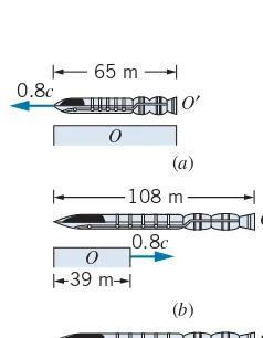
D0=65 m on a space station. A rocket passes at a relative speed of 0.80cmoving parallel to the edge of the platform. The observerOnotes that the front and back of the rocket simultaneously line up with the ends of the platform at a particular instant (Figure 2.13a). (a) According toO, what
0.8c
FIGURE 2.13 Example 2.6. (a) From the reference frame ofO
at rest on the platform, the passing rocket lines up simultane-ously with the front and back of the platform. (b,c) From the reference frameO′in the rocket, the passing platform lines up first with the front of the rocket and later with the rear. Note the differing effects of length contraction in the two reference frames.
is the time necessary for the rocket to pass a particular point on the platform? (b) What is the rest lengthL0of the rocket? (c) According to an observerO′on the rocket, what is the lengthDof the platform? (d) According toO′, how long does it take for observerOto pass the entire length of the rocket? (e) According toO, the ends of the rocket simultaneously line up with the ends of the platform. Are these events simultaneous toO′?
Solution
(a) According toO, the lengthLof the rocket matches the lengthD0of the platform. The time for the rocket to pass a particular point is measured byOto be
t0= L
0.80c =
65 m
2.40×10⁸m/s=0.27μs
This is a proper time interval, because O measures the interval between two events that occur at the same point in the frame of reference ofO(the front of the rocket passes a point, and then the back of the rocket passes the same point).
(b) Omeasures the contracted lengthLof the rocket. We can find its proper lengthL0using Eq. 2.13:
the platform is therefore
D=D01−u2/c2 =(65 m)1−(0.80)2 =39 m
(d) ForOto pass the entire length of the rocket, O′ con-cludes thatOmust move a distance equal to its rest length, or 108 m. The time needed to do this is
t′= 108 m
0.80c =0.45μs
Note that this isnota proper time interval forO′, who deter-mines this time interval using one clock at the front of the rocket to measure the time at whichOpasses the front of the rocket, and another clock on the rear of the rocket to mea-sure the time at whichOpasses the rear of the rocket. The two events therefore occur at different points inO′and so cannot be separated by a proper time inO′. The correspond-ing time interval measured byOfor the same two events, which we calculated in part (a),isa proper time interval for
O, because the two eventsdooccur at the same point inO.
The time intervals measured byOandO′should be related by the time dilation formula, as you should verify.
(e) According toO′, the rocket has a rest length ofL0= 108 m and the platform has a contracted length ofD=39 m. There is thus no way that O′ could observe the two ends of both to align simultaneously. The sequence of events according toO′is illustrated in Figures 2.13bandc. The time intervalt′inO′between the two events that are simulta-neous inOcan be calculated by noting that, according toO′, the time interval between the situations shown in Figures 2.13bandcmust be that necessary for the platform to move a distance of 108 m−39 m = 69 m, which takes a time
t′= 69 m
0.80c =0.29μs
This result illustrates the relativity of simultaneity: two events at different locations that are simultaneous toO(the lining up of the two ends of the rocket with the two ends of the platform)cannotbe simultaneous toO′.
Particle
Light P
D
F
L0
v
′FIGURE 2.14 In this timing device,
a particle is emitted byPat a speed
v′. When the particle reaches F, it triggers the emission of a flash of light that travels to the detectorD.
Relativistic Velocity Addition
The timing device is now modified as shown in Figure 2.14. A sourcePemits particles that travel at speedv′ according to an observerO′ at rest with respect to the device. The flashing bulbFis triggered to flash when a particle reaches it. The flash of light makes the return trip to the detectorD, and the clock ticks. The time intervalt0between ticks measured byO′is composed of two parts: one for the particle to travel the distanceL0at speedv′and another for the light to travel the same distance at speedc:
t0=L0/v′+L0/c (2.14) According to observerO, relative to whomO′moves at speedu, the sequence of events is similar to that shown in Figure 2.10. The emitted particle, which travels at speedvaccording to O, reachesF in a time interval t1 after traveling the distancevt1equal to the (contracted) lengthLplus the additional distanceut1 moved by the clock in that interval:
vt1=L+ut1 (2.15) In the intervalt2, the light beam travels a distancect2 equal to the lengthL
less the distanceut2moved by the clock in that interval:
ct2=L−ut2 (2.16) We now solve Eqs. 2.15 and 2.16 fort1 andt2, add to find the total interval
tbetween ticks according toO, use the time dilation formula, Eq. 2.8, to relate this result tot0 from Eq. 2.14, and finally use the length contraction formula, Eq. 2.13, to relateLtoL0. After doing the algebra, we find the result
v= v′+u
Equation 2.17 is the relativistic velocity addition lawfor velocity components that are in the direction ofu. Later in this chapter we use a different method to derive the corresponding results for motion in other directions.
We can also regard Eq. 2.17 as a velocity transformation, enabling us to convert a velocityv′measured byO′to a velocityvmeasured byO. The corresponding classical law was given by Eq. 2.2: v = v′ + u. The difference between the classical and relativistic results is the denominator of Eq. 2.17, which reduces to 1 in cases when the speeds are small compared withc. Example 2.7 shows how this factor prevents the measured speeds from exceedingc.
Equation 2.17 gives an important result when O′ observes a light beam. Forv′= c,
v= c+u
1+cu/c2 =c (2.18) That is, when v′=c, then v = c, independent of the value of u. All observers measure the same speed c for light, exactly as required by Einstein’s second postulate.
Example 2.7
A spaceship moving away from the Earth at a speed of 0.80c fires a missile parallel to its direction of motion (Figure 2.15). The missile moves at a speed of 0.60c rela-tive to the ship. What is the speed of the missile as measured by an observer on the Earth?
O′
ν′=0.60c
u=0.80c O
FIGURE 2.15 Example 2.7. A spaceship moves away from
Earth at a speed of 0.80c. An observerO′ on the spaceship fires a missile and measures its speed to be 0.60crelative to the ship.
Solution
HereO′is on the ship and Ois on Earth;O′moves with a speed ofu=0.80crelative toO. The missile moves at
speedv′=0.60c relative toO′, and we seek its speed v
relative toO. Using Eq. 2.17, we obtain
v= v′+u 1+v′u/c2 =
0.60c+0.80c
1+(0.60c)(0.80c)/c2
=1.40c
1.48 =0.95c
According to classical kinematics (the numerator of Eq. 2.17), an observer on the Earth would see the mis-sile moving at 0.60c+ 0.80c=1.40c, thereby exceeding the maximum relative speed of c permitted by relativ-ity. You can see how Eq. 2.17 brings about this speed limit. Even ifv′were 0.9999. . .canduwere 0.9999. . .c, the relative speed v measured by O would remain less thanc.
The Relativistic Doppler Effect
In the classical Doppler effect for sound waves, an observer moving relative to a source of waves (sound, for example) detects a frequency different from that emitted by the source. The frequencyf′heard by the observerOis related to the frequencyf emitted by the sourceSaccording to
f′=fv±vO v∓vS
(2.19)
and denominator are chosen wheneverS moves towardOorOmoves towardS, while the lower signs apply wheneverOandSmove away from one another.
The classical Doppler shift for motion of the source differs from that for motion of the observer. For example, suppose the source emits sound waves at
f =1000 Hz. If the source moves at 30 m/s toward the observer who is at rest in the medium (which we take to be air, in which sound moves atv=340 m/s), thenf′=1097 Hz, while if the source is at rest in the medium and the observer moves toward the source at 30 m/s, the frequency is 1088 Hz. Other possibilities in which the relative speed betweenS andOis 30 m/s, such as each moving toward the other at 15 m/s, give still different frequencies.
Here we have a situation in which it is not the relative speed of the source and observer that determines the Doppler shift—it is the speed of each with respect to the medium. This cannot occur for light waves, since there is no medium (no “ether”) and no preferred reference frame by Einstein’s first postulate. We therefore require a different approach to the Doppler effect for light waves, an approach that does not distinguish between source motion and observer motion, but involves only the relative motion between the source and the observer.
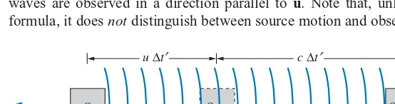
Consider a source of waves that is at rest in the reference frame of observer
O. ObserverO′moves relative to the source at speedu. We consider the situation from the frame of reference ofO′, as shown in Figure 2.16. SupposeOobserves the source to emitN waves at frequencyf. According toO, it takes an interval
t0=N/f for theseNwaves to be emitted; this is a proper time interval in the frame of reference ofO. The corresponding time interval toO′ ist′, during whichO moves a distance ut′. The wavelength according to O′ is the total length interval occupied by these waves divided by the number of waves:
λ′=ct
′+ut′
N =
ct′+ut′ ft0
(2.20)
The frequency according toO′isf′=c/λ′, so
f′=ft0 t′
1
1+u/c (2.21)
and using the time dilation formula, Eq. 2.8, to relatet′andt0, we obtain
f′=f
1−u2/c2 1+u/c =f
1−u/c
1+u/c (2.22)
This is the formula for therelativistic Doppler shift,for the case in which the waves are observed in a direction parallel to
u. Note that, unlike the classical formula, it doesnotdistinguish between source motion and observer motion; the
N waves
O′ O
O
u ∆t′ c ∆t′
–u
FIGURE 2.16 A source of waves, in the reference frame ofO, moves at speeduaway from observerO′. In the timet′(according toO′),O
relativistic Doppler effect depends only on the relative speedubetween the source and observer.
Equation 2.22 assumes that the source and observer are separating. If the source and observer are approaching one another, replaceuby−uin the formula.
Example 2.8
A distant galaxy is moving away from the Earth at such high speed that the blue hydrogen line at a wavelength of 434 nm is recorded at 600 nm, in the red range of the spectrum. What is the speed of the galaxy relative to the Earth?
Solution
Using Eq. 2.22 with f =c/λand f′=c/λ′, we obtain
c λ′ =
c λ
1−u/c
1+u/c
c
600 nm =
c
434 nm
1−u/c
1+u/c
Solving, we find
u/c=0.31
Thus the galaxy is moving away from Earth at a speed of 0.31c=9.4×10⁷m/s. Evidence obtained in this way indicates that nearly all the galaxies we observe are moving away from us. This suggests that the universe is expanding, and is usually taken to provide evidence in favor of the Big Bang theory of cosmology (see Chapter 15).
2.5 THE LORENTZ TRANSFORMATION
We have seen that the Galilean transformation of coordinates, time, and velocity is not consistent with Einstein’s postulates. Although the Galilean transformation agrees with our “common-sense” experience at low speeds, it does not agree with experiment at high speeds. We therefore need a new set of transformation equations that replaces the Galilean set and that is capable of predicting such relativistic effects as time dilation, length contraction, velocity addition, and the Doppler shift.
As before, we seek a transformation that enables observers O and O′ in relative motion to compare their measurements of the space and time coordinates of the same event. The transformation equations relate the measurements of O
(namely,x, y, z, t) to those ofO′(namely,x′, y′, z′, t′). This new transformation must have several properties: It must be linear (depending only on the first power of the space and time coordinates), which follows from the homogeneity of space and time; it must be consistent with Einstein’s postulates; and it must reduce to the Galilean transformation when the relative speed betweenOandO′is small. We again assume that the velocity ofO′relative toOis in the positivexx′direction.
This new transformation consistent with special relativity is called theLorentz transformation∗. Its equations are
x′= x−ut
1−u2/c2 (2.23a) y′=y (2.23b)
z′=z (2.23c)
t′= t−(u/c 2)x
1−u2/c2 (2.23d) It is often useful to write these equations in terms ofintervalsof space and time by replacing each coordinate by the corresponding interval (replacexbyx,x′
byx′,tbyt,t′byt′).
These equations are written assuming thatO′movesaway from Oin thexx′
direction. IfO′movestoward O, replaceuwith−uin the equations.
The first three equations reduce directly to the Galilean transformation for space coordinates, Eqs. 2.1, whenu≪c. The fourth equation, which links the time coordinates, reduces to t′=t, which is a fundamental postulate of the Galilean-Newtonian world.
We now use the Lorentz transformation equations to derive some of the predictions of special relativity. The problems at the end of the chapter guide you in some other derivations. The results derived here are identical with those we obtained previously using Einstein’s postulates, which shows that the equations of the Lorentz transformation are consistent with the postulates of special relativity.
Length Contraction
A rod of lengthL0is at rest in the reference frame of observerO′. The rod extends along thex′axis fromx′1tox′2; that is,O′measures the proper lengthL0=x′2−x′1. ObserverO, relative to whom the rod is in motion, measures the ends of the rod to be at coordinatesx1andx2. ForOto determine the length of the moving rod, Omust make asimultaneousdetermination ofx1 andx2, and then the length is
L=x2−x1. Suppose the first event isO′setting off a flash bulb at one end of the rod atx′1andt′1, whichOobserves atx1andt1, and the second event isO′setting off a flash bulb at the other end atx′2 andt′2, whichOobserves atx2andt2. The equations of the Lorentz transformation relate these coordinates, specifically,
x′1= x1−ut1
1−u2/c2 x
′
2=
x2−ut2
1−u2/c2 (2.24) Subtracting these equations, we obtain
x′2−x′1 =
x2−x1
1−u2/c2 −
u(t2−t1)
1−u2/c2 (2.25) O′ must arrange to set off the flash bulbs so that the flashes appear to be simultaneous toO. (They willnotbe simultaneous toO′, as we discuss later in this section.) This enablesOto make a simultaneous determination of the coordinates of the endpoints of the rod. IfOobserves the flashes to be simultaneous, then
t2=t1, and Eq. 2.25 reduces to
x′2−x′1= x2−x1
1−u2/c2 (2.26) Withx′2−x′1=L0andx2−x1 =L, this becomes
L=L0
Velocity Transformation
If Oobserves a particle to travel with velocity v(components vx,vy,vz), what
velocityv′doesO′observe for the particle? The relationship between the velocities measured byOandO′is given by theLorentz velocity transformation:
v′x= vx−u
1−vxu/c2
(2.28a)
v′y=vy
1−u2/c2 1−vxu/c2
(2.28b)
v′z=vz
1−u2/c2 1−vxu/c2
(2.28c)
By solving Eq. 2.28aforvx, you can show that it is identical to Eq. 2.17, a result we derived previously based on Einstein’s postulates. Note that, in the limit of low speeds (u≪c), the Lorentz velocity transformation reduces to the Galilean velocity transformation, Eq. 2.2. Note also thatv′y=vy, even thoughy′=y. This
occurs because of the way the Lorentz transformation handles the time coordinate. We can derive these transformation equations for velocity from the Lorentz coordinate transformation. By way of example, we derive the velocity trans-formation forv′y=dy′/dt′. Differentiating the coordinate transformationy′=y,
we obtaindy′=dy. Similarly, differentiating the time coordinate transformation (Eq. 2.23d), we obtain
dt′= dt−(u/c 2)dx
1−u2/c2 So
v′y=
dy′ dt′ =
dy
[dt−(u/c2)dx]/
1−u2/c2 =
1−u2/c2 dy dt−(u/c2)dx
=1−u2/c2 dy/dt
1−(u/c2)dx/dt =
vy1−u2/c2 1−uvx/c2
Similar methods can be used to obtain the transformation equations forv′xand
v′z. These derivations are left as exercises (Problem 14). Clock 1
x= 0 x=L/2 x=L
Clock 2
O O′
FIGURE 2.17 A flash of light, emitted
from a point midway between the two clocks, starts the two clocks simulta-neously according toO. ObserverO′
sees clock 2 start ahead of clock 1.
Simultaneity and Clock Synchronization
Under ordinary circumstances, synchronizing one clock with another is a simple matter. But for scientific work, where timekeeping at a precision below the nanosecond range is routine, clock synchronization can present some significant challenges. At very least, we need to correct for the time that it takes for the signal showing the reading on one clock to be transmitted to the other clock. However, for observers who are in motion with respect to each other, special relativity gives yet another way that clocks may appear to be out of synchronization.
Consider the device shown in Figure 2.17. Two clocks are located atx=0 and
receive the flash of light from the lamp. The light takes the same interval of time to reach the two clocks, so the clocks start together precisely at a timeL/2cafter the flash is emitted, and the clocks are exactly synchronized.
Now let us examine the same situation from the point of view of the moving observerO′. In the frame of reference ofO, two events occur: the receipt of a light signal by clock 1 atx1=0,t1=L/2cand the receipt of a light signal by clock 2 atx2 =L,t2=L/2c. Using Eq. 2.23d, we find thatO′observes clock 1 to receive its signal at
t′1=
t1−(u/c2)x 1
1−u2/c2 =
L/2c
1−u2/c2 (2.29) while clock 2 receives its signal at
t′2=
t2−(u/c2)x2
1−u2/c2 =
L/2c−(u/c2)L
1−u2/c2 (2.30) Thust′2 is smaller than t′1 and clock 2 appears to receive its signal earlier than clock 1, so that the clocks start at times that differ by
t′=t′1−t′2= uL/c 2
1−u2/c2 (2.31) according to O′. Keep in mind that this is not a time dilation effect—time dilation comes from thefirstterm of the Lorentz transformation (Eq. 2.23d) fort′, while the lack of synchronization arises from thesecondterm.O′observesboth
clocks to run slow, due to time dilation;O′alsoobserves clock 2 to be ahead of clock 1.
We therefore reach the following conclusion: two events that are simultaneous in one reference frame are not simultaneous in another reference frame moving with respect to the first, unless the two events occur at the same point in space. (If L=0, Eq. 2.31 shows that the clocks are synchronized in all reference frames.) Clocks that appear to be synchronized in one frame of reference will not necessarily be synchronized in another frame of reference in relative motion.
It is important to note that this clock synchronization effect does not depend on thelocationof observerO′but only on thevelocityofO′. In Figure 2.17, the location ofO′could have been drawn far to the left side of clock 1 or far to the right side of clock 2, and the result would be the same. In those different locations, the propagation time of the light signal showing clock 1 starting will differ from the propagation time of the light signal showing clock 2 starting. However,O′
is assumed to be an “intelligent” observer who is aware of the locations where the light signals showing the two clocks starting are received relative to the locations of the clocks.O′corrects for this time difference, which is due only to the propagation time of the light signals, andeven after making that correction
the clocks still do not appear to be synchronized!
Example 2.9
Two rockets are leaving their space station along perpen-dicular paths, as measured by an observer on the space station. Rocket 1 moves at 0.60c and rocket 2 moves at 0.80c, both measured relative to the space station. What is the velocity of rocket 2 as observed by rocket 1?
Solution
Observer Ois the space station, observer O′ is rocket 1 (moving atu=0.60c), and each observes rocket 2, moving (according toO) in a direction perpendicular to rocket 1. We take this to be theydirection of the reference frame of
O. ThusOobserves rocket 2 to have velocity components
vx=0,vy=0.80c, as shown in Figure 2.18a.
Thus, according toO′, the situation looks like Figure 2.18b. The speed of rocket 2 according to O′ is
(0.60c)2+(0.64c)2 =0.88c, less thanc. According to
the Galilean transformation,v′ywould be identical withvy, and thus the speed would be(0.60c)2+(0.80c)2=c. Once again, the Lorentz transformation prevents relative speeds from reaching or exceeding the speed of light.
(a)
FIGURE 2.18 Example 2.9. (a) As viewed from the reference frame ofO. (b) As viewed from the reference frame ofO′.
Example 2.10
In Example 2.6, two events that were simultaneous to O
(the lining up of the front and back of the rocket ship with the ends of the platform) were not simultaneous toO′. Find the time interval between these events according toO′.
Solution
According toO, the two simultaneous events are separated by a distance ofL=65 m. Foru=0.80c, Eq. 2.31 gives
which agrees with the result calculated in part (e) of Example 2.6.
2.6 THE TWIN PARADOX
run slow relative to his own and that therefore she should be younger than he when she returns, as our discussion of time dilation would suggest. However, recalling that discussion, we know that for two observers in relative motion,eachthinks the
other’sclocks are running slow. We could therefore study this problem from the point of view of Amelia, according to whom Casper and the Earth (accompanied by the solar system and galaxy) make a round-trip journey away from her and back again. Under such circumstances, she will think it is her brother’s clocks (which are now in motion relative to her own) that are running slow, and will therefore expect her brother to be younger than she when they meet again. While it is possible to disagree over whose clocks are running slow relative to his or her own, which is merely a problem of frames of reference, when Amelia returns to Earth (or when the Earth returns to Amelia), all observers must agree as to which twin has aged less rapidly. This is the paradox—each twin expects the other to be younger.
The resolution of this paradox lies in considering the asymmetric role of the two twins. The laws of special relativity apply only to inertial frames, those moving relative to one another at constant velocity. We may supply Amelia’s rockets with sufficient thrust so that they accelerate for a very short length of time, bringing the ship to a speed at which it can coast to the planet, and thus during her outward journey Amelia spends all but a negligible amount of time in a frame of reference moving at constant speed relative to Casper. However, in order to return to Earth, she must decelerate and reverse her motion. Although this also may be done in a very short time interval, Amelia’s return journey occurs in a completely different inertial frame than her outward journey. It is Amelia’s jump from one inertial frame to another that causes the asymmetry in the ages of the twins. Only Amelia has the necessity of jumping to a new inertial frame to return, and thereforeall observers will agreethat it is Amelia who is “really” in motion, and that it is her clocks that are “really” running slow; therefore she is indeed the younger twin on her return.
Let us make this discussion more quantitative with a numerical example. We assume, as discussed above, that the acceleration and deceleration take negligible time intervals, so that all of Amelia’s aging is done during the coasting. For simplicity, we assume the distant planet is at rest relative to the Earth; this does not change the problem, but it avoids the need to introduce yet another frame of reference. Suppose the planet to be 6 light-years distant from Earth, and suppose Amelia travels at a speed of 0.6c. Then according to Casper it takes his sister 10 years (10 years ×0.6c=6 light-years) to reach the planet and 10 years to return, and therefore she is gone for a total of 20 years. (However, Casper doesn’t know his sister has reached the planet until the light signal carrying news of her arrival reaches Earth. Since light takes 6 years to make the journey, it is 16 years after her departure when Casper sees his sister’s arrival at the planet. Four years later she returns to Earth.) From the frame of reference of Amelia aboard the rocket, the distance to the planet is contracted by a factor of1−(0.6)2=0.8, and is therefore 0.8×6 light-years = 4.8 light-years. At a speed of 0.6c, Amelia will measure 8 years for the trip to the planet, for a total round trip time of 16 years. Thus Casper ages 20 years while Amelia ages only 16 years and is indeed the younger on her return.
by Amelia will be Doppler shifted. During the outward journey, she will receive signals at the rate of
(1/year)
1−u/c
1+u/c =0.5/year
During the return journey, the Doppler-shifted rate will be
(1/year)
1+u/c
1−u/c=2/year
Thus for the first 8 years, during Amelia’s trip to the planet, she receives 4 signals, and during the return trip of 8 years, she receives 16 signals, for a total of 20. She receives 20 signals, indicating her brother has celebrated 20 birthdays during her 16-year journey.
FIGURE 2.19 A spacetime diagram.
Spacetime Diagrams
A particularly helpful way of visualizing the journeys of Casper and Amelia uses aspacetimediagram. Figure 2.19 shows an example of a spacetime diagram for motion that involves only one spatial direction.
In your introductory physics course, you probably became familiar with plotting motion on a graph in which distance appeared on the vertical axis and time on the horizontal axis. On such a graph, a straight line represents motion at constant velocity; the slope of the line is equal to the velocity. Note that the axes of the spacetime diagram are switched from the traditional graph of particle motion, with time on the vertical axis and space on the horizontal axis.
On a spacetime diagram, the graph that represents the motion of a particle is called itsworldline. Theinverseof the slope of the particle’s worldline gives its velocity. Equivalently, the velocity is given by the tangent of the angle that the worldline makes with thevertical axis (rather than with the horizontal axis, as would be the case with a conventional plot of distancevs. time). Usually, the units ofxandtare chosen so that motion at the speed of light is represented by a line with a 45◦ slope. A vertical line represents a particle that is at the same spatial locations at all times—that is, a particle at rest. Permitted motions with constant velocity are then represented by straight lines between the vertical and the 45◦ line representing the maximum velocity.
Let’s draw the worldlines of Casper and Amelia according to Casper’s frame of reference. Casper’s worldline is a vertical line, because he is at rest in this frame (Figure 2.20). In Casper’s frame of reference, 20 years pass between Amelia’s departure and her return, so we can follow Casper’s vertical worldline for 20 years.
FIGURE 2.20 Casper’s spacetime
di-agram, showing his worldline and Amelia’s.
Amelia is traveling at a speed of 0.6c, so her worldline makes an angle with the vertical whose tangent is 0.6 (31◦). In Casper’s frame of reference, the planet visited by Amelia is 6 light-years from Earth. Amelia travels a distance of 6 light-years in a time of 10 years (according to Casper) so thatv=6 light-years/10 years = 0.6c.
It is left as an exercise (Problems 22 and 24) to consider the situation if it is Amelia who is sending the signals.
2.7 RELATIVISTIC DYNAMICS
We have seen how Einstein’s postulates have led to a new “relative” interpretation of such previously absolute concepts as length and time, and that the classical concept of absolute velocity is not valid. It is reasonable then to ask how far this revolution is to go in changing our interpretation of physical concepts. Dynamical quantities, such as momentum and kinetic energy, depend on length, time, and velocity. Do classical laws of momentum and energy conservation remain valid in Einstein’s relativity?
Let’s test the conservation laws by examining the collision shown in Figure 2.21a. Two particles collide elastically as observed in the reference frame of O′. Particle 1 of mass m1=2mis initially at rest, and particle 2 of massm2=m is moving in the negative xdirection with an initial velocity of v′2i = −0.750c. Using the classical law of momentum conservation to analyze this collision,O′would calculate the particles to be moving with final velocities
v′1f = −0.500cand v′2f = +0.250c. According to O′, the total initial and final momenta of the particles would be:
p′i=m1v′1i+m2v′2i =(2m)(0)+(m)(−0.750c)= −0.750mc p′f =m1v′1f+m2v′2f =(2m)(−0.500c)+(m)(0.250c)= −0.750mc
The initial and final momenta are equal according to O′, demonstrating that momentum is conserved.
Suppose that the reference frame ofO′moves at a velocity ofu= +0.550cin thexdirection relative to observerO, as in Figure 2.21b. How would observer
Oanalyze this collision? We can find the initial and final velocities of the two particles according toOusing the velocity transformation of Eq. 2.17, which gives
Initial Initial
Final Final
2m
2m
m
m
(a)
y′
x′
v2′i= −0.750c v1i= 0.550c v2i= −0.340c
u= 0.550c
v′2f v1f v2f
v′1f
2m m
2m m
(b)
y
x
FIGURE 2.21 (a) A collision between two particles as observed from the reference frame of O′.