POLE PHOTOGRAMMETRY WITH AN ACTION CAMERA FOR FAST AND
ACCURATE SURFACE MAPPING
J. A. Gonçalves a,b, *, O. F. Moutinho a, A. C. Rodrigues a
a University of Porto, Science Faculty, Rua Campo Alegre, 4169-007, Porto, Portugal - [email protected],
[email protected], [email protected]
b CIIMAR - Interdisciplinary Centre of Marine and Environmental Research, Porto, Portugal
Inter Commission WG I/Va
KEY WORDS: High resolution, Orientation, Point Cloud, Accuracy, Change Detection
ABSTRACT:
High resolution and high accuracy terrain mapping can provide height change detection for studies of erosion, subsidence or land slip. A UAV flying at a low altitude above the ground, with a compact camera, acquires images with resolution appropriate for these change detections. However, there may be situations where different approaches may be needed, either because higher resolution is required or the operation of a drone is not possible. Pole photogrammetry, where a camera is mounted on a pole, pointing to the ground, is an alternative. This paper describes a very simple system of this kind, created for topographic change detection, based on an action camera. These cameras have high quality and very flexible image capture. Although radial distortion is normally high, it can be treated in an auto-calibration process. The system is composed by a light aluminium pole, 4 meters long, with a 12 megapixel GoPro camera. Average ground sampling distance at the image centre is 2.3 mm. The user moves along a path, taking successive photos, with a time lapse of 0.5 or 1 second, and adjusting the speed in order to have an appropriate overlap, with enough redundancy for 3D coordinate extraction. Marked ground control points are surveyed with GNSS for precise georeferencing of the DSM and orthoimage that are created by structure from motion processing software. An average vertical accuracy of 1 cm could be achieved, which is enough for many applications, for example for soil erosion. The GNSS survey in RTK mode with permanent stations is now very fast (5 seconds per point), which results, together with the image collection, in a very fast field work. If an improved accuracy is needed, since image resolution is 1/4 cm, it can be achieved using a total station for the control point survey, although the field work time increases.
* Corresponding author.
1. INTRODUCTION
High resolution and high accuracy terrain mapping can provide data for the detection of height changes due to several reasons, as erosion, or mass movements (James and Robson, 2012). LiDAR systems can provide important data but they are expensive and not accessible to many users, especially for small areas. Automatic methods, based on Structure from Motion (SfM) can provide dense and rigorous point clouds only from images, with obvious advantages in terms of costs (James and Robson, 2012, Raugust and Olsen, 2013). Several studies of applications have been published in geomorphology (Fonstad et al., 2013, Westoby et al., 2014, Johnson et al., 2014).
Very high resolution mapping from drones are now common and can be done with very good positional accuracy. A drone flying 20 meters above the ground, with a compact camera, acquires images with a ground sampling distance (GSD) of around 1 cm. Provided that ground control exists with that positional accuracy, current processing software, based on SfM algorithms, will allow for the extraction of very accurate and detailed surface models. Studies of landslide analysis have been carried for example by Niethammer et al. (2011).
However, there may be situations where different approaches may be needed, either because higher resolution is required or the operation of a drone is not possible, due to obstacles or legal
use. Pole photogrammetry, where a camera is mounted on a pole, pointing to the ground, is an alternative.
Action cameras are now very popular. Although they are normally presented as video cameras, they provide very good quality discrete images, normally with resolutions of 12 megapixels, as is the case of the GoPro Hero 4. Images can be acquired in time lapse mode, with rates of one or more images per second, for thousands of continuous images (Digital Photography Review, 2014). Another interesting aspect of action cameras is the large field view, which can cover large areas, when compared to other compact cameras. Action cameras are normally associated with large distortion, making their photogrammetric use difficult. However, as Baletti et al. (2014) show, they can be calibrated using a standard distortion model, and yield good photogrammetric results.
This paper describes a very simple surveying system based on an action camera mounted on a pole, thought for applications such as erosion assessment. An analysis of the accuracy that can be achieved in several different conditions is presented.
The system takes advantage of the availability of permanent GNSS networks, which allow for real time differential corrections (real time kinematics, RTK) through internet. Ground control points can be surveyed with centimetric accuracy in very short times of a few seconds. This requires The International Archives of the Photogrammetry, Remote Sensing and Spatial Information Sciences, Volume XLI-B1, 2016
only one receiver, equipped with a GSM data communication for internet access in the field.
Structure from motion processing was done with Photoscan (Agisoft, 2016), in order to achieve a digital surface model (DSM) and an ortho-mosaic.
2. DESCRIPTION OF THE METHODOLOGY
The methodology implemented is very simple, low cost and of fast execution. Details of the image acquisition system, ground control point collection and data processing are given below.
2.1 Pole and camera
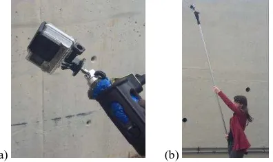
The system is composed by an extensible rod, with maximum length of 4 meters, and a small tripod attached at one end, where the camera is fixed (Figure 1). The camera inclination can be adjusted in the tripod. The rod, made of aluminium, is very light and can be held vertically by the operator, so that the camera will be at least 5 meters above the ground. It can also be kept slightly tilted, in order that the camera axis becomes closer to the vertical direction (Figure 1 b).
(a) (b)
Figure 1. GoPro camera fixed in a small tripod at the end of the rod (a); the rod held tilted, by an operator (b).
The camera is a GoPro Hero 4, which can be controlled by wifi. An application in a smartphone displays the images and allows to start and stop image collection.
The camera has a resolution of 12 megapixels (4000 x 3000) in discrete image capture. It has a continuous shooting mode (time lapse mode) with a nominal maximum rate of 2 images per will be 6.9 m by 9.2 m, assuming no radial distortion, to which corresponds a ground sampling distance (GSD) of 2.3 mm.
A separation of 1 meter between consecutive photos leads to an overlap of 85%, in the direction of the smaller image side. The system is mainly intended for corridor mapping, with a single strip. For areas wider than 9.2 meters, overlapping strips can be made, with the appropriate care of operator to move in parallel lines.
2.2 Ground control
Precise image orientation requires ground control points, with an appropriate distribution throughout the area. Although
natural points, such as paintings on the pavement, may exist, it is preferable to use marked points. In the present work, points were marked with chalk. In cases where that is not possible, as bare soil or sand, a set of signals printed in a rigid material were prepared. In any case it is convenient that they are numbered in order to facilitate point identification. Figure 2 shows both types of points.
(a) (b)
Figure 2. Images of the types of points used: (a) point marked with chalk and (b) signals.
The easiest way to survey the points is by dual frequency GNSS, in RTK mode (real time kinematics). With the availability of permanent station networks, providing differential corrections in real time, on the internet, very high accuracy can be achieved in very short observation times. In the case of Portugal the network used was RENEP (National Network of Permanent Stations) operated by the Portuguese national mapping agency (DGT, 2016).
In the present work, a Trimble R6 receiver was used. Typically this type of receiver achieves an accuracy of 1 or 2 cm in 5 to 10 seconds of observation per point. The GCP collection becomes very fast in this way.
Positional accuracy at centimetre level may be appropriate for many situations, but, since the GSD is 2.3 mm, a better accuracy of the GCPs would improve the digital surface model to be extracted. For that, longer observation time per point and post processing is needed. Another alternative is to survey the points with a total station. In any case the operation time of the field work increases significantly.
In order to verify the vertical accuracy of the DSM to be extracted it is advisable to survey some independent altimetric check points, which don’t need to be marked. This is important to certify that deformations in the model do not exist. The time taken to survey these extra points is small if GNSS-RTK is used.
2.3 Structure from motion processing
The processing methodology designated as SfM is essentially a method of automatic triangulation, of images not necessarily acquired in a regular manner, as in conventional photogrammetry. A free bundle adjustment is done with large number of conjugate points obtained by algorithms similar to SIFT (Lowe, 2004). This initial relative orientation process, normally called “image alignment”, is followed by an absolute orientation with ground control points. Since non-metric cameras are normally used, it is usual to include an auto-calibration in the image orientation. The following step is the generation of a dense point cloud, by multi-view stereo matching, which leads to a digital surface model (DSM) and an ortho-rectified image mosaic.
This processing is appropriate for the images acquired by the GoPro camera, which includes large radial distortion, and The International Archives of the Photogrammetry, Remote Sensing and Spatial Information Sciences, Volume XLI-B1, 2016
obviously is not a metric camera. The software used was Agisoft Photoscan (Agisoft, 2016), which does all the SfM processing, and exports a DSM and an ortho rectified mosaic in standard GIS formats. It incorporates a functionality of image rectification if radial distortion parameters are known, which was used.
2.4 Pre-calibration
The GoPro camera incorporates large radial distortions that need to be determined in the auto-calibration process. In some cases of processing original GoPro images the image alignment process did not converge to an appropriate solution, originating a sparse point cloud with obvious deformations. It was decided to do some form of previous camera calibration.
From some successful initial test surveys a set of calibration parameters (focal distance, principal point position and three coefficients of the radial distortion) were considered as an approximation of the camera distortion. The focal distance was reduced from the nominal value (3 mm) by 2.5%. The principal point was displaced by 44 pixels in x and 14 pixels in y direction. Figure 3 shows an original image and the corresponding undistorted image. A points on the corner of the rectified image suffered a displacement of 650 pixels from its position on the original image.
Figure 3. Original image and the corresponding undistorted image obtained with the approximate camera calibration.
In further surveys images were previously rectified, and the orientation process was run over the undistorted images. Since the initial rectification is only an approximation, the bundle adjustment is done with the auto-calibration for a refinement of the interior orientation.
3. TESTS CARRIED OUT
Tests were carried out at the Astronomical Observatory of the University of Porto. Some paths with a total length of 240 meters were surveyed. The average speed of the operator was 1 m/s, which led to an average separation of 0.7 meters between consecutive photos. The paths were covered twice, in opposite directions, leading to a total of 680 photos.
A total of 29 points were marked and surveyed with GNSS-RTK, with 5 seconds average time per point. The estimated accuracy provided by the real time processing were, on average, 1.0 cm in planimetry and 1.5 cm in altimetry. From these points, 14 were used as GCPs and 15 as independent check points of the orientation process (XYZ Check Points). Some unmarked points (a total of 77) were also surveyed to be used as check points of the DSM heights.
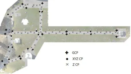
Figure 4 shows the surveyed area, with the location of the three types of points. The maximum length of the surveyed area is 110 m.
The points were also surveyed with a total station, all from the same station. The expected accuracy is of 3 mm. In the case of
the height check points, only 23 were surveyed with total station.
Figure 4. Test area and location of control and check points.
4. IMAGE ORIENTATION RESULTS
Undistorted images were input and went through the initial step of image alignment. It is followed by the identification of GCP and ICP locations, which is a manual procedure in Photoscan. It took some time because all points were found in more than 20 images. The bundle adjustment was then made, with the choice of further refinement of the interior orientation parameters. The ones considered were the focal distance, the principal point position, 3 polynomial coefficient of radial distortion and 2 tangential parameters.
4.1 Orientation with GNSS points
The process was initially done with the GNSS points. Residuals are provided for the GCPs and the ICPs. Table 1 shows the statistics of the residuals: minimum, maximum, average and root mean square of the residuals. Being the orientation process a least squares adjustment, the average of the GCP residuals is zero.
As would be expectable, residuals in the ICPs are slightly larger than for the GCPs. The obtained values are of the order of the GNSS accuracy, but better in the height component.
14 GCPs ICPs
Table 1. Statistics of the residuals found on the GNSS points, in centimetres.
These errors have a contribution from the photogrammetric process but, certainly a larger contribution from the GCP and ICP accuracy.
4.2 Orientation with total station points
The process was repeated, now replacing the coordinates with the ones obtained by the total station survey. It could be observed that residuals decreased, both for the GCPs and ICPs, as shown in Table 2. In the case of the height, which again performed better, the improvement was approximately by a factor of 2.
Although there was an improvement, the errors are still larger than the image resolution (0.23 cm). Even in this case it is not difficult that the surveying procedures (mark definition, verticality of the prism, measurement of instrument height, etc.) introduce several mm errors. Anyway, this accuracy is enough for most of the intended applications.
14 GCPs 15 ICPs
E N H E N H
Min -1.8 -1.2 -0.5 -1.7 -2.1 -1.5
Max 1.5 2.0 0.4 2.5 3.3 0.2
Mean 0 0 0 0.0 0.6 -0.5
RMSE 1.0 0.9 0.3 1.4 1.6 0.7
Table 2 – Statistics of the residuals found on total station points, in centimetres.
5. DSM ANALYSIS
The following step was the generation of a dense point cloud, which was done in one fourth of the resolution, i.e., one pixel matched in every 4 by 4 image pixels. This leads to an approximate density of 1 point per square centimetre. This operation for 680 images took approximately 5 hours.
The DSM was created in the form of a 1 cm grid, which is good to describe very small details of the ground surface. Some visual inspection was done, together with an altimetric residual analysis.
5.1 Visual analysis
Figure 5 shows the DSM in colours, with hill shading. The height range in the area was 4.3 meters.
Figure 5. Colored DSM, with hill shading effect.
Visual inspection of the DSM shows very fine detail on the pavement. No discontinuities were found. Vertical objects, such as some pillars that exist in the area, are shown with acceptable detail.
An orthoimage mosaic was also built. Figure 6 shows (a) a smaller area, with the DSM and contours with 10 cm interval, and (b) the ortho of the same area also with the contours.
(a) (b)
Figure 6. Colored DSM (a) and orthoimage (b) of a smaller area, with 10 cm vertical spacing contours.
5.2 Residual analysis
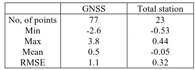
A quantitative assessment of the DSM heights was made with the altimetric check points. Residuals in the check points are calculated as the difference between the measured height and the heights calculated from the DSM grid, using bilinear interpolation. Table 3 contains the statistics of the residuals in the check points, obtained by both surveying methods.
GNSS Total station
No, of points 77 23
Min -2.6 -0.53
Max 3.8 0.44
Mean 0.5 -0.05
RMSE 1.1 0.32
Table 3. Statistics of the height errors found (cm) in the altimetric check points (GNSS and total station).
There was a clear improvement for the DSM obtained from images oriented with total station points. As residuals became of milimetric order, they were shown with one more digit. Results are now closer to the image resolution: RMS of 3.2 mm, slightly more than the image GSD (2.3 mm).
6. CONCLUSIONS
The system described is of very low cost and of fast field data collection, when control points are surveyed with GNSS. Vertical accuracy of the extracted surface model had an RMSE of around 1 cm. Although much more time is taken for the total station survey, accuracy can be improved to a few millimeters, close to the image resolution. Anyway it must be noticed that all control and check points were located in flat areas. Some accuracy loss may be expected if the surface is rougher and control points have to be located in place with some slope. The system is being tested in new situations, of actual erosion assessment, in order to be more thoroughly validated.
A limitation of the method is related to the increase of the area covered, and consequently the number of images. Processing times tend to be extremely large. To avoid this, some optimization can be done by reducing the time interval between images, without compromising accuracy. This will be done in future work
ACKNOWLEDGEMENTS
The GNSS National Network of Permanent Stations (RENEP) of “Direcção Geral do Território” was used for differential corrections.
REFERENCES
Agisoft, 2016. Agisoft documentation: internet address http://www.agisoft.com/pdf/photoscan-pro_1_2_en.pdf (assessed on March 2016).
Digital Photography Review, 2014. Available online: www.dpreview.com (accessed on March 2016).
Lowe, D. 2004. Distinctive Image Features from Scale-Invariant Keypoints. International Journal of Computer Vision. Vol. 60, No. 2, pp. 91-110.
Fonstad, M.A., Dietrich, J.T., Courville, B.C., Jensen, J.L., and Carbonneau, P.E., 2013, Topographic structure from motion: a new development in photogrammetric measurement, Earth Surface Processes and Landforms, v. 38, p. 421-430.
James, M.R., Robson, S., 2012. Straightforward reconstruction of 3D surfaces and topography with a camera: accuracy and geoscience application. Journal of Geophysical Research, v. 117, F03017.
Johnson, K., Nissen, E., Saripalli, S., Arrowsmith, J.R., McGarey, P., Scharer, K., Williams, P., and Blisniuk, K., 2014. Rapid mapping of ultrafine fault zone topography with structure from motion. Geosphere, v. 10, no. 5, p. 969-986.
Niethammer, U., Rothmund, S., Schwaderer, U., Zeman, J., Joswig, M., 2011. Open source image-processing tools for low-cost UAV-based landslide investigations. Int. Arch. Photogram. Remote Sensing Spatial Info. Sci., 38, 1–6.
Raugust, J.D., Olsen, M.J., 2013. Emerging technology: structure from motion. LiDAR Magazine, v. 3, no. 6, 5 p.
Westoby, M.J., Brasington, J., Glasser, N.F., Hambrey, M.J., and Reynolds, J.M., 2012. Structure from motion photogrammetry: a low-cost, effective tool for geoscience applications. Geomorphology, v. 179, p. 300-314.