AN INTEGRATED RAPID MAPPING SYSTEM FOR DISASTER MANAGEMENT
Daniel Heina∗, Steven Bayera, Ralf Bergera, Thomas Krafta, Daniela Lesmeisterb,
aInstitute of Optical Sensor Systems, DLR German Aerospace Center - (daniel.hein, steven.bayer, ralf.berger, thomas.kraft)@dlr.de b
I.S.A.R. Germany Stiftung gGmbH - [email protected]
Commission IV, ICWG III/IVa
KEY WORDS:UAV Camera System, Rapid Mapping, MACS, Disaster Management, Real-Time, Real-Time Situation Picture, Pro-jective Mapping
ABSTRACT:
Natural disasters as well as major man made incidents are an increasingly serious threat for civil society. Effective, fast and coordinated disaster management crucially depends on the availability of a real-time situation picture of the affected area. However, in situ situation assessment from the ground is usually time-consuming and of limited effect, especially when dealing with large or inaccessible areas. A rapid mapping system based on aerial images can enable fast and effective assessment and analysis of medium to large scale disaster situations. This paper presents an integrated rapid mapping system that is particularly designed for real-time applications, where comparatively large areas have to be recorded in short time. The system includes a lightweight camera system suitable for UAV applications and a software tool for generating aerial maps from recorded sensor data within minutes after landing. The paper describes in particular which sensors are applied and how they are operated. Furthermore it outlines the procedure, how the aerial map is generated from image and additional gathered sensor data.
1. INTRODUCTION AND MOTIVATION
Humanitarian relief in case of major disasters is a global task. Several international organizations and institutes take specific ac-tions for its coordination and execution.
1.1 GLOBAL ORGANIZATION
The Office for the Coordination of Humanitarian Affairs (OCHA1) is part of theUnited Nations(UN) secretariat and is responsible for bringing together humanitarian actors to ensure a coherent response to emergencies, such as earthquakes, typhoons or conflicts. OCHA’s mission is to mobilize and coordinate ef-fective humanitarian action in partnership with national and inter-national actors in order to alleviate human suffering in disasters and emergencies. Towards major disasters OCHA ascertain the humanitarian needs of the affected government and is coordinat-ing international relief actions. Rapid-response tools are served as well such as theUnited Nations Disaster Assessment and Co-ordination(UNDAC2) system and theInternational Search and Rescue Advisory Group(INSARAG3).
INSARAG deals withurban search and rescue(USAR) related issues, aiming to establish minimum international standards for USAR teams and methodology for international coordination in earthquake response. UNDAC is part of the international emer-gency response system for sudden-onset emergencies and assess-ment teams can be deployed at short notice (12-48 hours) any-where in the world. They are provided free of charge to disaster-affected countries. In case of sudden-onset emergency UNDAC installs an On-Site-Operations-Coordination-Center (OSOCC) and a Reception-Departure-Centre (RDC) for coordinating all
∗Corresponding author
1
www.unocha.org
2
www.unocha.org/what-we-do/coordination-tools/undac/overview
3
www.insarag.org
following relief actions. Due to communication between inter-national responders andLocal Emergency Management Authori-ties(LEMA) all available information will be gathered to assess the current situation of disaster-affected areas. TheGlobal Dis-aster Alert and Coordination System(GDACS4) is used to share these information. GDACS is a cooperation framework and it in-cludes disaster managers and disaster information systems world-wide and aims at filling the information and coordination gap in the first phase after major disasters. GDACS provides real-time access to webbased disaster information systems and related co-ordination tools.
I.S.A.R. Germany Stiftung GmbH5is an INSARAG certified non-profit organization which is able and allowed to shortly send first responder, search-and-rescue (SAR) and medical teams into disaster-affected areas. Furthermore, they manage to setup OSOCC and RDC and experienced in coordinating relief actions in the first phase after major disasters.
1.2 DISASTER ASSESSMENT
An effective coordination requires reliable and up-to-date infor-mation based on the assessment of disaster-affected areas. Based on the given information by LEMA additional technologies are used. Free access maps (e.g. Google Maps, OpenStreetMap, MapAction) will enable the identification of overtures and pop-ulated areas (Center for Satellite Based Crisis Information (ZKI), 2015). Those maps give a pre-disaster overview and are used for navigation issues too. The usage of latest satellite data depends on the availability of appropriate satellite imagery services, cur-rent weather conditions and obtainable infrastructure for access-ing those maps on site (Voigt et al., 2007). In major scenarios he-licopter systems are commonly used, although its operation is ex-pensive and relies on existing infrastructure (R¨omer et al., 2013).
4
www.gdacs.org
5
The assessment is often done by car, which is usually time con-suming due to degraded infrastructure. In the last few years small UAV camera systems has been increasingly used for mapping and monitoring disasters-affected areas (Swiss Foundation for Mine Action (FSD), 2016a). Monitoring is often done by capturing sin-gle aerial images or video streams and transmitting the live-view directly to the ground. It is mainly used for assessing damages of roads and buildings (DuPlessis, 2016b, Alschner et al., 2016, Swiss Foundation for Mine Action (FSD), 2016b). Lightweight vertical take-off and landing(VTOL) UAVs (e.g. MikroKopter, AscTec Falcon8,DJI Phantom,DJI Inspire) allow a mean flight time of 20 minutes per battery and can be used to a range of up to
5km. This makes it an ideal tool for assessing close surroundings from the birds-eye of view (Meier, 2015, McFarland, 2015).
1.3 UAV-BASED MAPPING - STATE OF PLAY
Several software tools enable map or even 3D point cloud gener-ation out of (more or less arbitrary) aerial imagery (e.g. Agisoft Photoscan,Pix4D,Capturing Reality). Their underlying struc-ture from motion(SFM) process is relatively time and resource consuming, due to extensive image analysis and matching (Tomasi and Kanade, 1992, Pollefeys et al., 1999). By the use of small fixed wing UAVs (e.g.SenseFly eBee,Trimble UX5) large areas can be covered but the time for post processing of several hours have to be considered (Swiss Foundation for Mine Action (FSD), 2016a).
Current assessment operations commonly use small rotorcraft UAVs due to their vertical take-off and landing capabilities. On the other hand, such UAVs have a rather limited operation time and cruise speed. As a result these systems are not capable of cap-turing larger areas within a short time. Fixed wing UAVs need flat space for landing which may be limited in e.g. destroyed urban or mountainous areas. But - in contrast to rotorcraft UAVs - they allow for mapping and monitoring larger surroundings. Since the last few years VTOL fixed wings UAVs are available (e.g. Quantum Systems,Germandrones, Wingcopter) which combine the strength of both concepts.
UAVs are an ideal tool for accessing remote areas but the latest solutions for generating maps are not fast enough to add value to tactical decision-making in the first stage of emergency response. This paper presents a camera system and post processing tool chain that enables both, capturing large areas and subsequent fast and automated generating high resolution interactive maps. It is a common development ofGerman Aerospace Center(DLR) and I.S.A.R. Germany. By using a VTOL fixed wing UAV with a less than10kgmaximum take-off weight (MTOW6) the complete set-up forms a compact and portable system with the ability to cap-ture large areas and deliver maps within an hour. Our aim is to provide scaled maps on a daily basis to enable the assessment of remote areas for identifying damages of populated areas and re-maining overtures. By providing those maps to GDACS we hope to essentially improve and support international relief actions.
2. UAV CAMERA SYSTEM
The DLR MACS7 UAV camera system basically consists of a geometric and radiometric calibrated industrial 16MPx camera with a high end GNSS8L1/L2 receiver in combination with an
6
maximum take off weight
7
modular airborne camera system; www.dlr.de/MACS
8
global navigation satellite system
industrial grade inertial measurement unit (IMU) and an embed-ded computing board with exchangeable CFast storage module. The modular design is based on preceding aerial camera systems, developed byGerman Aerospace Center(DLR) (Lehmann et al., 2011).
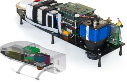
The GNSS is laid out as a dual antenna system to improve the ori-entation accuracy and allow for very fast attitude initialization. Superior light sensitivity, fast readout electronics and data han-dling allow for short integration times and high frame rates which enables the system to be used on fast flying carriers. The com-plete camera system weighs about1.4kgand can be used even in small UAVs with a MTOW of less than10kg.
Figure 1. DLR MACS UAV camera system: Upper right: assembled prototype. Lower left: CAD model with UAV
silhouette
The camera system is able to operate fully autonomously. The complete configuration settings is set up prior to the flight and contains, among other things, trigger frequency, exposure times, and optionally recording areas. After initial configuration the camera system operates without any further human interaction. Within the defined target area the system triggers the camera sen-sor and records all captured image data to the storage module. All subsidiary sensor data like GNSS/IMU is recorded too. The current set-up with a 64GB storage module allows recording up to about2,900images or in terms of duration depending on trig-ger frequency a net recording time from20minutes up to about
60minutes. The system is capable of using CFast storage mod-ules of up to 512GB.
Camera and lens are designed for an operational flight altitude between100and500metres above ground (AGL9) and a flight speed up to 120km/h. The corresponding ground sampling dis-tance is then between about 1.5cm (swath width ∼72m) and
7.5cm(swath width∼360m) per pixel. The maximum area that can be captured within a single flight depends on storage capac-ity and the overlapping between adjacent footprints, which in turn depends on flight altitude, flight speed, trigger frequency and dis-tance between adjacent flight strips. At an assuming average im-age overlap of60%, a 64GB storage module allows for capturing areas of up to 3.8km2
at100m altitude AGL, or rather up to about92km2
at500maltitude AGL.
A core prerequisite for the here presented rapid mapping method is the real-time tagging of camera’s position and orientation ex-actly at time of exposure to each recorded aerial image. For this
9
purpose, a hardware synchronization between camera sensor and GNSS/IMU enables accurate capture and fusion of the current GPS time, location and orientation of the camera system for every single aerial image. The real-time GNSS/IMU data in combina-tion with the images serve as basis for immediate map generacombina-tion directly after landing.
3. RAPID MAPPING TECHNOLOGY
After landing, the recorded images and sensor data can immedi-ately used for generating a quick mosaic of the recorded area.
3.1 Intersection algorithm
The following prerequisites are required for the presented rapid mapping procedure:
• elevation model of recorded target area (i.e.R2
⇒R, speci-fying an elevation for every two-dimensional geographic co-ordinate within target area)
• interior orientation of applied camera (i.e. primarily focal length and sensor size)
• aerial images with position and orientation for every single aerial image
• optionally: boresight axis and angle, specifying spatial rela-tionship between camera sensor and IMU
• optionally: radiometric correction model of applied camera • optionally: geometric correction model of applied camera
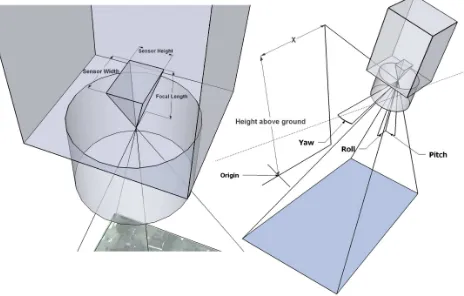
The basic principle is based on spatial intersection of image rays (i.e. rays of its corresponding pinhole camera in space) and eleva-tion model. For every single aerial image, its interior and exterior orientation and optionally boresight alignment determine exactly each pixel’s ray in space (see figure 2). The intersection between the rays and elevation model can then be calculated either within a (geo-) spherical or a cartesian coordinate system. The latter one is given e.g. by aerial images’ corresponding UTM10zone (Snyder, 1987).
Figure 2. Pinhole camera in space: Interior orientation (left side) and exterior orientation (right side) define rays of camera sensor.
In general, derivations can not be determined for a given eleva-tion model. Hence analytic solueleva-tions or numerical approaches
10
universal transversal mercator projection
like newton method cannot be applied for determining a ray’s in-tersection point with the elevation model. We therefore propose an iterative approach that will work with arbitrary models:
Assume a rayR, starting at pointS(i.e. the position of camera at time of exposure), and a particular direction, resulting from forementioned conditions (i.e. line of sight of a particular pixel). RayRis then divided into equidistant sections defining sampling points{r0, r1, ...}, wherer0 = S. The section length depends
on a reasonable sampling distance, given by elevation model’s spatial resolution.
Starting at point ri = r0, for each sampling point
r∈ {r0, r1, ...}do:
• determine elevationh(ri)at pointri
• calculate elevation difference ∆z(ri) = z(ri) −h(ri),
wherez(ri)iszcomponent ofri(i.e. height ofri)
• stop iterating, if∆z(ri) <0(i.e. ribelow height model,
thus ray intersected elevation model)
Assume iteration nfulfils abort criteria. Intersection pointIR
between rayRand elevation model is then given by∆z
-inverse-weighted linear interpolation between the last two sample points
rn−1andrn. Figure 3 illustrates the proposed iterative algorithm.
R
r1 r0
r2
r3
r4
r5
r6 elevation model
h(r )0 h(r )1 h(r )2 h(r )3 h(r )4 h(r )5 h(r )6
IR
z(r )0 z(r )1
z(r )2
sampling distance
Figure 3. Determination of intersection: gradual evaluation of vertical distance between sampling pointsrnand its elevation
h(rn)leads to (approximated) intersection pointIR
Following this algorithm, all four sensor corner rays of an aerial image can be intersected with the given elevation model. The four obtained intersection points represent a rough footprint of the images’ captured area. This geo-referenced polygon is then used for the projective mapping of the corresponding image.
3.2 PROJECTIVE MAPPING
In order to draw an aerial image onto a map (i.e. a geo-referenced coordinate system), we determine aprojective mappingfor every single image. This mapping consists of a homogeneous transfor-mation matrix, that specifies aR2
⇒R2
Figure 4. Projective mapping: aerial image and its perspective projection by application of corresponding transformation matrix
Sequential drawing of several aerial images, with application of their corresponding transformation matrices, yields a seamless, geo-referenced quick mosaic of the captured area. Modern com-puter systems support hardware accelerated transformation-based rendering. This enables a fast and smooth visualization of several hundreds up to several thousands of such aerial images within the corresponding scene. A sample scene is shown in figure 6.
The mapping quality can be enhanced additionally by radiometric and geometric correction of the aerial images (Weng et al., 1992, Kannala and Brandt, 2006, Kelcey and Lucieer, 2012). This re-quires appropriate calibration procedures of the applied camera. Whilst geometric correction increases the image-interior projec-tion accuracy, a radiometric correcprojec-tion may in particular reduce vignetting effects and thus smoothing radiometric characteristics of the mosaic.
3.3 Accuracy
Despite the highly simplified projection, which is based just on the interpolation between the four projected polygon corners, within soft terrains the resulting mosaic provides a quite accurate aerial map (see figure 6).
However, the resulting aerial map may have projection errors. The following four points mainly influence the overall quality and position accuracy of the emerged mosaic:
• Accuracy and resolution of applied elevation model. • Projective errors and masking effects engendered by raised
objects. This affects primarily projection results of man-made objects like buildings or towers, especially if not cov-ered by elevation model.
• Inaccuracies of position and proximity sensors. Roll and pitch angle errors may in particular significantly arouse po-sitional projection inaccuracies.
• Projection errors resulting from linear interpolation within single aerial image projection.
These sources of errors may lead to positional errors (horizon-tal shifts), masking effects and visual discontinuities (breaking edges) between adjacent projected images. The positional accu-racy of the proposed approach has been evaluated in (Brauchle
et al., 2017). It states a horizontal position error of less than
2metres for the set-up with a standard utility aircraft and a flight altitude of2,600f t(approx.780m) above ground and compara-ble camera and sensors. The accuracy assessment for the set-up with a small UAV platform is going to be made within further tests and evaluations.
4. APPLICATION AND RESULTS
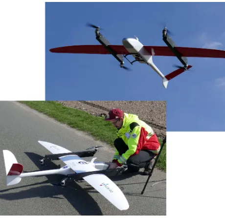
The presented rapid mapping system is going to be evaluated for search-and-rescue missions within an international rescue exer-ciseACHILLES 2017 leaded by the UN in Switzerland (NRZ, 2017). The VTOL fixed wing UAVSongbirdofGermandrones11 is chosen as carrier platform (see figure 5). Since it provides a net operation time of about 60 minutes, supports payloads up to
1.4kgby an average cruise speeds of80km/h, it fulfils all essen-tial requirements set by rescue exercises’ demands. It provides a fully autonomous operation and thus flights even beyond line of sight. In combination with the proposed DLR MACS aerial cam-era system sevcam-eral square kilometres can be covered quickly.
Figure 5. VTOL-UAVSongbirdbyGermandroneswith DLR MACS UAV aerial camera system.
In context of the preceding trainings and upcoming exercise, the camera systems was integrated into the UAV and several test flights were performed at training base Weeze12on 25th of March, 2017. The altitude was limited to250mdue to law restrictions (BMVI, 2016). Table 1 summarizes the key figures of two sample flights.
After each performed flight, a quick mosaic of the captured area was generated. On average, the complete mosaic was available within about 20 minutes after landing, whereby the main part is taken by copying the aerial images.
The quick mosaic is rendered within a special developed software tool (see figure 6), which provides several GIS13functionalities like e.g. meta data handling, measurement functions and export-ing scaled maps for subsequent processexport-ing. TheSRTMmodel
11
http://germandrones.com
12
http://www.trainingbaseweeze.com
13
Flight 1 Flight 2
Altitude (AGL) 150m 250m
GSD 2.2cm 3.8cm
Exposure time 750us 400us
Flight strips 8 4
Strip length 900m 1500m
Captured area 0.5km2
1.0km2
Overlap in track 80% 80%
Overlap cross track 60% 60%
Captured images 860 625
Processing time 15min 10min
Table 1. Key figures of performed test flights
Figure 6. Quick-mosaic of a captured area comprising about
800,000m2
. The visualized scene is rendered out of1,093
single aerial images (approx. 20GB image data) with an average ground resolution of about3.5cm. A detail view of the yellow
rect section is shown in figure 7
Figure 7. Detail view of quick-mosaic shown in figure 6 (yellow rect section) with a ground sampling distance of3.5cmper
pixel.
with a spatial resolution of three arcsecond (∼90m) is used as el-evation model (The Shuttle Radar Topography Mission (SRTM), 2000). It provides near-global scale elevation data, can be used
freely and with its size of approx. 16GB it is comparatively lightweight even for mobile applications.
The mosaic of Flight 2 was exported as GeoTIFF image in full resolution within 12 minutes. As part of the exercise byI.S.A.R. Germanythis data was used by the management for assessing the disaster-affected area. Damaged buildings, overtures, heli-copter landing spots and suitable locations for theBase of Op-eration(BoO) were identified clearly. The mosaic was used as additional GIS layer for coordinating relief actions. Furthermore, geo-referenced maps and single images of potentially search-and-rescue sites were added intoVirtual OSOCCofGDACSfor de-tailed on-site assessment. Finally the maps were printed and used on tablet computers (usingPathAwayApp14) for navigating to these sites by assessment teams.
5. CONCLUSION AND OUTLOOK
The work presented here constitutes a first rapid mapping system for search-and-rescue teams. It has the potential to significantly change and improve disaster management and first response op-erations.
Nonetheless, several aspects may improve the overall systems performance. Current work focusses on enhancing the geometric projection onto the elevation model by using more than the four corner rays for intersection. This will in particular reduce pro-jection errors within more complex structured regions like moun-tains or steep slopes. Another subject focusses on image match-ing and its application for reducmatch-ing discontinuities between adja-cent images and thus improving the overall position quality of the resulting aerial map. A long-term purpose is the extraction of 3D information of the captured area as fast as possible. This could avoid the need for a preliminary elevation model or even generate a higher resolution one.
Regarding hardware we evaluate different camera sensors, pro-viding higher light sensitivity for low light or even night appli-cations, or providing additional spectral bands for e.g. thermal visualization of treated areas (DuPlessis, 2016a). Finally we ex-amine data link options, both for remote controlling and teleme-try data of the camera system (narrow band links) as well as real-time image transmission (broadband links). Data links and its application for real-time aerial image transmission with standard utility aircraft operations were already surveyed in (Bucher et al., 2016). Based on these findings we will prove its integration into the present prototype.
Another aim is the optimization of image recording based on actual ground speed. On the whole, targeted overlap between consecutively captured images exactly defines the optimum trig-ger timing. Hence a ground-speed or respectively position-aware triggering could optimize the resulting vantage points.
Within ACHILLES 2017 we evaluate the prototype over three days in cooperation with additional actors to achieve further re-quirements. Our aim is to build up an appropriate solution which can be used byI.S.A.R. Germanyfor real disaster relief missions.
REFERENCES
Alschner, F., DuPlessis, J. and Soesilo, D., 2016. Using drone im-agery for real-time information after typhoon haiyan in the philip-pines. http://drones.fsd.ch/wp-content/uploads/2016/06/9Case-Study.Philippine.SearchRescue.3May2016.pdf.
14
BMVI, 2016. Kurzinformation ¨uber die Nutzung von unbeman-nten Luftfahrtsystemen. Bundesministerium f¨ur Verkehr und dig-itale Infrastruktur.
Brauchle, J., Bayer, S., Hein, D., Berger, R. and Pless, S., 2017. Macs-mar: A real-time remote sensing system for maritime se-curity applications.CEAS Space Journal.
Bucher, T., Berger, R., Brauchle, J., Hein, D., Lehmann, F., Piltz, B., Scherbaum, P., Stebner, K. and Pless, S., 2016. Mod-ular photogrammetric sensor systems for real-time information extraction and 3d-applications. In: T. P. Kersten (ed.), 36. Wissenschaftlich-Technische Jahrestagung der DGPF, Publika-tionen der Deutschen Gesellschaft f¨ur Photogrammetrie, Fern-erkundung und Geoinformation e.V., Vol. 25.
Center for Satellite Based Crisis Information (ZKI), 2015. Earthquake in nepal on april 25, 2015. https://www.zki.dlr.de/article/2748.
DuPlessis, J., 2016a. Using drones in fire and rescue services in the united kingdom. http://drones.fsd.ch/wp-content/uploads/2016/11/12.Manchester.pdf.
DuPlessis, J., 2016b. Using drones to inspect post-earthquake road damage in ecuador. http://drones.fsd.ch/wp-content/uploads/2016/11/13.Case-StudyEcuador3.pdf.
Hartley, R. and Andrew Zisserman, A., 2004.Multiple View Ge-ometry in Computer Vision. Second edn, Cambridge University Press.
Heckbert, P., 1989. Projective mappings for image warping. In: In in Fundamentals of Texture Mapping and Image Warping (Paul Heckbert, Masters Thesis), UC.
Kannala, J. and Brandt, S. S., 2006. A generic camera model and calibration method for conventional, wide-angle, and fish-eye lenses. IEEE Transactions on Pattern Analysis and Machine Intelligence28(8), pp. 1335–1340.
Kelcey, J. and Lucieer, A., 2012. Sensor Correction and Radio-metric Calibration of a 6-BAND Multispectral Imaging Sensor for Uav Remote Sensing. ISPRS - International Archives of the Photogrammetry, Remote Sensing and Spatial Information Sci-encespp. 393–398.
Lehmann, F., Berger, R., Brauchle, J., Hein, D., Meißner, H. and Pless, S., 2011. Macs - modular airborne camera system for gen-erating photogrammetric high-resolution products.Zeitschrift der Deutschen Gesellschaft f¨ur Geowissenschaften2011(6), pp. 435– 446.
McFarland, M., 2015. In nepal, a model
for using drones for humanitarianism emerges. www.washingtonpost.com/news/innovations/wp/2015/10/07/in-nepal-a-model-for-using-drones-for-humanitarianism-emerges.
Meier, P., 2015. Digital humanitarians - how big data is changing the face of humanitarian response. http://www.digital-humanitarians.com/.
NRZ, 2017. I.S.A.R. Germany bei 72-Stunden- ¨Ubung. http://www.nrz.de/staedte/kleve-und-umland/i-s-a-r-bei-72-stunden-uebung-id210088203.html.
Pollefeys, M., Koch, R. and Gool, L. V., 1999. Self-calibration and metric reconstruction inspite of varying and unknown intrin-sic camera parameters.International Journal of Computer Vision 32(1), pp. 7–25.
R¨omer, H., Kersten, J., Kiefl, R., Plattner, S., Mager, A. and Voigt, S., 2013. Airborne near real-time monitoring of assembly and parking areas in case of large scale public events and natu-ral disasters. International Journal of Geographical Information Science28(4), pp. 682–699.
The Shuttle Radar Topography Mission (SRTM), 2000. http://www2.jpl.nasa.gov/srtm (Feb. 2000).
Snyder, J. P., 1987. Map projections – A working manual. U.S. Geological Survey professional paper, U.S. Government Printing Office.
Swiss Foundation for Mine Action (FSD), 2016a. Drones in humanitarian action. http://drones.fsd.ch/en/independent-report-drones-are-ready-for-disasters.
Swiss Foundation for Mine Action (FSD), 2016b. Using drones to create maps and assess building damage in ecuador. http://drones.fsd.ch/wp-content/uploads/2016/11/14.Case-StudyEcuador.pdf.
Tomasi, C. and Kanade, T., 1992. Shape and motion from image streams under orthography: a factorization method.International Journal of Computer Vision9(2), pp. 137–154.
Voigt, S., Kemper, T., Riedlinger, T., Kiefl, R., Scholte, K. and Mehl, H., 2007. Satellite image analysis for disaster and crisis-management support.IEEE Transactions on Geoscience and Re-mote Sensing45(6), pp. 1520–1528.