STRUCTURE-FROM-MOTION FOR CALIBRATION OF A VEHICLE CAMERA SYSTEM
WITH NON-OVERLAPPING FIELDS-OF-VIEW IN AN URBAN ENVIRONMENT
A. Hanela, U. Stillaa a
Photogrammetry & Remote Sensing, Technische Universitaet Muenchen, Germany - (alexander.hanel, stilla)@tum.de
Commission I, WG 9
KEY WORDS:vehicle cameras, camera calibration, structure from motion, bundle adjustment
ABSTRACT:
Vehicle environment cameras observing traffic participants in the area around a car and interior cameras observing the car driver are important data sources for driver intention recognition algorithms. To combine information from both camera groups, a camera system calibration can be performed. Typically, there is no overlapping field-of-view between environment and interior cameras. Often no marked reference points are available in environments, which are a large enough to cover a car for the system calibration. In this contribution, a calibration method for a vehicle camera system with non-overlapping camera groups in an urban environment is described. A-priori images of an urban calibration environment taken with an external camera are processed with the structure-from-motion method to obtain an environment point cloud. Images of the vehicle interior, taken also with an external camera, are processed to obtain an interior point cloud. Both point clouds are tied to each other with images of both image sets showing the same real-world objects. The point clouds are transformed into a self-defined vehicle coordinate system describing the vehicle movement. On demand, videos can be recorded with the vehicle cameras in a calibration drive. Poses of vehicle environment cameras and interior cameras are estimated separately using ground control points from the respective point cloud. All poses of a vehicle camera estimated for different video frames are optimized in a bundle adjustment. In an experiment, a point cloud is created from images of an underground car park, as well as a point cloud of the interior of a Volkswagen test car is created. Videos of two environment and one interior cameras are recorded. Results show, that the vehicle camera poses are estimated successfully especially when the car is not moving. Position standard deviations in the centimeter range can be achieved for all vehicle cameras. Relative distances between the vehicle cameras deviate between one and ten centimeters from tachymeter reference measurements.
1. DRIVER OBSERVATION FOR DRIVER INTENTION RECOGNITION
One of the big goals in the automotive industry is to reduce the number of traffic fatalities to zero (Volvo Vision 2020 (Samuels-son, 2017)). An important part on this way is to know the inten-tion of a car driver for the next seconds in advance. Currently available cars are therefore equipped with environment cameras to collect information about other traffic participants around the own car. For example, environment cameras can capture a pre-ceding car slowing down on the rightmost lane and having acti-vated the right turn indicator. Advanced driver assistance systems can use driver intention recognition algorithms to anticipate, that the preceding car driver wants to turn right.
To anticipate the intention of the own car driver, interior cameras observing his behavior (figure 1) can be used in addition. Their images can be used to extract features about the driver’s head movement and his gaze direction. The intention recognition can be made more reliable, if information from the environment and interior cameras is combined. For example, combined evalua-tion allows to evaluate, whether the driver has noticed the slower car in front of him or is distracted by the car radio, for exam-ple. Therefore, his head orientation and gaze direction have to be linked to the position of the other car relative to his car. Basis for this geometric link is the known relative position and orien-tation (pose) of the interior and exterior vehicle cameras to each other. A system calibration for the vehicle cameras can be used to estimate these parameters.
For calibration of a vehicle camera system, a calibration envi-ronment large enough to contain a car is required, as well as the
Figure 1: A driver camera can be used to extract features from images to recognize the driver intention of the next seconds as an important milestone to increase traffic safety (Volvo, 2014).
3d coordinates of reference points can be calculated automati-cally by triangulating image features of urban structures shown in multiple images. However, as the vehicle interior cameras are showing nearly only the interior space of the car, reference infor-mation of the urban structures is not available for them. Other reference information has to be used for these cameras, and the reference information for both environment and interior cameras has to be linked together for a system calibration.
As costs are a very important factor in the automotive industry, the number of cameras is kept small. This leads in addition to non-overlapping fields-of-view, making the camera system cal-ibration using tie points in overlapping image parts impossible. Due to their wide field-of-view and their low costs, so called “ac-tion cameras” can cover a huge part of the environment around a car despite their small number. Therefore, it has to be considered, that the wide field-of-view might cause large image distortions requiring reliable single camera calibration.
In addition, the camera mounting on the window panes of the car might not be rigid over time caused by mechanical movements during a car drive. To check the vehicle camera poses again and again, the system calibration has to be repeated from time to time, requiring a calibration process which can be performed with low effort, for example before and after every video recording drive.
The camera system calibration provides information about the relative poses of the vehicle cameras. To know, whether a pedes-trian shown in one of the environment camera images is behind or in front of the own car, the camera poses have to be linked to the pose of the car. This can be done by transforming the cam-era poses into a vehicle coordinate system, which describes the movement direction of the car. As ground control points for the transformation, physical points on the car surface corresponding to the vehicle coordinate system have to be chosen.
2. STATE OF THE ART
2.1 Camera calibration
Geometric calibration is performed on single cameras to estimate the interior orientation as well as image distortion parameters (Brown, 1971), (Fraser, 2013), (Hartley and Zisserman, 2004). Different models, like perspective pinhole models or fisheye mod-els can be used (Abraham and Förstner, 2005), (Schwalbe, 2005). Geometric calibration can be also performed on multiple cam-eras simultaneously to estimate the relative poses of the camcam-eras (Gruen and Beyer, 2001), wherefore typically calibration patterns are used. For calibration of commercial vehicle camera systems, manufacturer-specific calibration patterns are required, which are only available in calibration laboratories (glassBYTEs.com, 2015). Recently published approaches do not require calibration patterns anymore for system calibration of rigid camera systems (Esquivel et al., 2007), (Kazik et al., 2012), (Schneider and Förstner, 2013).
2.2 Structure from motion
The structure-from-motion (SfM) method is used for 3d recon-struction (‘structure’) of objects shown in an image set, whereby the movement of the camera between different images is used as stereo base line (Koenderink et al., 1991), (Sturm and Triggs, 1996). The usual pipeline (e.g. (Häming, 2010)) is to extract features from images and to match them with each other. Cam-era poses are estimated and 3d points triangulated and optimized in a bundle adjustment. There are different software toolboxes available for structure-from-motion, a well known example from
the literature is VisualSFM (Wu, 2007), (Wu, 2011), (Wu et al., 2011).
Camera system calibration and structure from motion can be com-bined by using reconstructed 3d points of a space to calibrate a camera system (Hanel and Stilla, 2017). The method in the cited paper requires, that each camera can see the 3d reference points, which might not be true for vehicle interior cameras.
2.3 Street scene datasets
Like for the vehicle camera system proposed in this contribu-tion, vehicle cameras are often used to collect street scene data. Among others, typically vehicle environment cameras (e.g. for datasets Kitti (Geiger et al., 2012), Cityscapes (Cordts et al., 2016)) are used for data collection. For the mentioned datasets, the in-terior and exin-terior calibration parameters of the camera systems are provided. Vehicle interior cameras are used only for some datasets, e.g. provided by Brain4Cars (Jain et al., 2015), while this dataset does not provide calibration parameters for the cam-eras.
3. VEHICLE CAMERA SYSTEM CALIBRATION IN AN URBAN ENVIRONMENT
In this section, a method (figure 2) to calibrate a vehicle camera system with environment and interior cameras without overlap-ping fields-of-view using unmarked reference points from urban structures and from the vehicle interior is described.
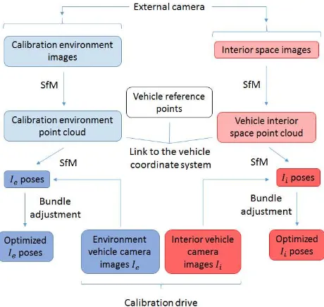
Figure 2: Process workflow to estimate the poses of vehicle envi-ronmentIeand vehicle interior camerasIiwith non-overlapping fields-of-view in an urban environment.
For pre-processing, each camera is calibrated separately in a lab-oratory environment to undistort all images. The main process chain can be divided into an a-priori part, which has to be done once with images of an external photographic camera before cali-brating the vehicle camera system and the calibration part, which is repeated every time the vehicle camera system should be cali-brated.
with images of urban structures in the calibration environment (environment images). Another point cloud of the interior space of the vehicle (interior point cloud) is created using structure-from-motion with images of the vehicle interior (interior images). Both point cloud coordinate systems are connected with common reference points and transformed into a vehicle coordinate system using reference points describing the vehicle movement.
In the calibration part, the poses of the vehicle cameras are esti-mated. Images of the vehicle environment cameras are matched with the environment images to use the 3d points of the environ-ment point cloud as ground control points for pose estimation of the vehicle environment cameras in the vehicle coordinate sys-tem. The same way, images of the vehicle interior cameras are matched with interior images and the 3d points of the interior point cloud used for pose estimation of the vehicle interior cam-eras in the vehicle coordinate system. Finally, all vehicle camera poses are adjusted using separate bundle adjustments for environ-ment and for interior cameras.
3.1 Single camera calibration
The single camera calibration is performed for each camera to re-duce the degrees of freedom for the point cloud creation and the pose estimation. The following process is used: A planar calibra-tion pattern with photogrammetric marks is captured in images with different camera positions, orientations and distances to the pattern plane. The interior orientation parameters (focal length in x/ydirection, principal point inx/ydirection) as well as radial and tangential image distortion parameters are estimated (Con-rady, 1919), (Brown, 1971).
The following radial distortion model is used (equations 1, 2):
xdist,rad=x·(1 +k1r2+k2r4+k3r6) (1)
ydist,rad=y·(1 +k1r2+k2r4+k3r6) (2)
withxdist,rad, ydist,rad as distorted image coordinates,x, yas undistorted image coordinates,ras radial distance ofx, yfrom the principal point andk1, k2, k3as radial distortion parameters.
The following tangential distortion model is added (equations 3, 4):
xdist=xdist,rad+ [2p1xy+p2(r2+ 2x2)] (3)
ydist=ydist,rad+ [p1(r2+ 2y2) + 2p2xy] (4)
withp1, p2as tangential distortion parameters.
To calculate the desired camera parameters, the sum over all im-ages and pattern points of the reprojection errors from 3d pat-tern points into the images is minimized using the Levenberg-Marquardt optimization. The images of each camera are undis-torted using the parameters obtained by camera calibration before processing the following steps.
3.2 Point cloud creation
This and the following parts of the method are the a-priori part of the processing, i.e. they have to be done once to be able to calibrate the vehicle camera system. The images used in this part are taken with an additional camera, not by the vehicle cameras.
In the a-priori part of the processing, the environment point cloud of urban structures (e.g. building walls, signs) in the calibration environment has to be created, as well as the interior point cloud of the interior of the camera-carrying vehicle has to be created. For the environment point cloud, a high number of overlapping
environment images is taken within the calibration environment. SIFT features (Lowe, 1999) are extracted from these images and used to match the images with each other. The point cloud is cre-ated using the structure-from-motion method, providing 3d point coordinates for the SIFT feature matches and also 3d coordinates for the camera poses. Only 3d points with matches between at least three images are accepted for further processing.
For the interior point cloud, interior images are taken in the inte-rior space of the vehicle and also the SfM method applied to get the 3d point coordinates for the SIFT feature matches.
Both image sets need to have overlapping images showing the same objects to transform one point cloud coordinate system into the other.
3.3 Transformation into the vehicle coordinate system
Both point cloud coordinate systems are transformed into the ve-hicle coordinate system to create a link between the estimated vehicle poses (see subsections 3.4, 3.5) to the driving direction of the camera-carrying car.
This step consists of two parts: Connecting the two point cloud coordinate systems to each other and transforming the connected point cloud coordinate system of the into the vehicle coordinate system.
For step one, 3d coordinates of common reference points shown in both environment images and interior images are used. The in-terior point cloud is transformed into the environment point cloud coordinate system using a similarity transform (equation 5):
x′=s·R·x+t (5)
withx′, xtarget and source 3d point coordinates, and the
param-eterssas scale,Ras rotation matrix andtas translation vector.
Figure 3: Vehicle coordinate system. Origin is the center of the front axle. Y-axis is equal to front axle, x-axis through front and rear axle and orthogonal to y-axis. Z-axis is orthogonal to the other two axes. Vehicle cameras of the test car are shown in blue (F = front, D = driver, R = rear), position of the cameras at the arrow tail, viewing direction like arrows (Volkswagen, 2017).
For step two, the vehicle coordinate system (figure 3) is defined by both axles of the car. It is assumed, that both axles are at the same height above ground, i.e. the vehicle coordinate system is parallel to the ground. The center of the front axle is defined as the origin of the vehicle coordinate system. The x-axis goes through the center of both the front and rear axle, pointing in driving direction, assuming that this definition describes the driv-ing direction of the car. The y-axis is equal to the front axle, pointing to the left side of the car. The z-axis is orthogonal to the two other axes and pointing away from the ground.
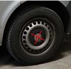
The transformation uses the rim centers (figure 4) of the four wheels as ground control points. It is assumed, that the rim cen-ters are the extension of the car axles. As modern car wheels have independent suspension, the camera-carrying chassis is only par-allel to the rim centers, if the car is standing on a level plane.
Figure 4: Rim centres (red cross) are used as ground control points for the transformation into the vehicle coordinate system. The emblem of the car manufacturer is often placed in the rim center providing a clear defined central point.
The image points showing the rim centers in environment images are used to calculate the 3d coordinates of the rim centers in the point cloud coordinate system. The 3d coordinates of the rim centers in the vehicle coordinate system can be calculated for ex-ample from a blueprint of the car manufacturer providing length information for relevant vehicle parts, like the wheel base.
The transformation is applied to the connected point cloud coor-dinate system, providing the point clouds in the vehicle camera system.
3.4 Pose estimation of vehicle environment cameras
This and the following parts of the method are the calibration part of the processing chain, i.e. they have to be performed every time the calibration of the vehicle cameras should be repeated.
Videos of the vehicle cameras recorded during a calibration drive of the car within the calibration environment are used for pose estimation of the vehicle cameras with the SfM method. SIFT features are extracted from the vehicle environment camera im-ages, the features used to match the vehicle camera images to each other and to the environment images. The matches between the environment images and the vehicle camera images allow to use the 3d points of the environment point cloud as ground con-trol points to estimate the poses of the vehicle environment cam-eras.
3.5 Pose estimation of vehicle interior cameras
For pose estimation of the vehicle interior cameras, videos recorded at the same time as the videos of the environment cameras (sub-section 3.4) are used. Also SIFT features are extracted to match the vehicle interior camera images to each other and to the inte-rior images. Thereby, the inteinte-rior point cloud is used as reference information to estimate the poses of the vehicle interior cameras.
3.6 Pose optimization by bundle adjustment
The poses of the vehicle environment cameras and the vehicle interior cameras are optimized in separate bundle adjustments. As there is no overlap between the two image sets of the vehicle cameras, two separate bundle adjustments are required.
The environment images and the images of the vehicle environ-ment cameras are processed together in one bundle adjustenviron-ment. The 3d coordinates of the point cloud and the corresponding im-age coordinates are introduced as adjustable parameters. A-priori values for these parameters are obtained from the environment point cloud (subsection 3.2) and the pose estimation (subsection 3.4). The exterior orientations of the cameras are introduced as adjustable parameters, too; the a-priori values for the exterior orientations are taken from the poses estimated with SfM (sub-sections 3.2, 3.4). The interior orientations of the cameras and their distortion parameters are kept fixed on the values from sin-gle camera calibration (subsection 3.1), as the sinsin-gle camera cali-bration can provide higher certainty for these values than the SfM method.
Bundle adjustment is done by a least-squares adjustment based on collinearity equations (equations 6, 7):
xij=x0j−cj· R11j(Xi−X0j) +R21j(Yi−Y0j) +R31j(Zi−Z0j) R13j(Xi−X0j) +R23j(Yi−Y0j) +R33j(Zi−Z0j)
(6)
yij=y0j−cj· R12j(Xi−X0j) +R22j(Yi−Y0j) +R33j(Zi−Z0j) R13j(Xi−X0j) +R23j(Yi−Y0j) +R33j(Zi−Z0j)
(7)
withX, Y, Zas 3d world coordinates,x, yas image coordinates, x0, y0, cas parameters of the interior orientation,X0, Y0, Z0 as
the camera position in world coordinates andRdescribing the camera orientation. Indexirepresents ground control points, in-dexjrepresents images.
For the least-squares adjustment, the residuals between the mea-sured image coordinates and the image coordinates calculated us-ing the estimated camera parameters and point coordinates are minimized.
The interior images and the images of the vehicle interior cam-eras are processed together in another bundle adjustment. Con-straints for vehicle camera poses are not introduced into the bun-dle adjustment, as the camera system might not be rigid due to the non-rigid mounting with suction pads on window panes and mechanical movements during the calibration drive.
4. TEST DATA ACQUISITION AND PROCESSING
The calibration environment is within an underground car park. The environment itself has a parking lot on one side of a drive-way, and two parking lots on the other side. The car park is built of concrete, in some parts painted white, and therefore without strong textures. Some signs are painted onto the walls. The only illumination source is a neon lamp at the ceiling, providing darker light than natural daylight. The car park is chosen, as the illumi-nation does not change over time and there are no moving objects (e.g. tree leafs, persons). The experiments are conducted in the late evening when the car park is empty and there are no cars leaving or entering the garage.
Figure 5: View onto the test car windshield against the driving direction. The front environment camera (red rectangle) is look-ing at the area in front of the car and the interior driver camera (purple rectangle) is looking at the car driver. Photogrammetric marks on the calibration pattern are used as ground control points to link the driver camera to the vehicle coordinate system.
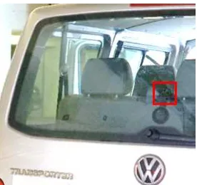
Figure 6: View onto the rear window pane of the test car. The rear environment camera (red rectangle) is looking at the area behind the car. Image brightness increased strongly for better visualization.
A-priori to the vehicle camera calibration, 143 images of the cali-bration environment are taken with an external DSLR camera (ta-ble 1) to create the environment point cloud with the SfM toolbox VisualSFM. In some of these images, photogrammetric marks placed on walls of the calibration environment are shown. 162 images are taken of the front seat row in the test car to create the interior point cloud. Some of these images contain a planar pattern with photogrammetric marks.
Camera Nikon D3
Lens 24 mm fixed focal length
Geometrical resolution 4,256 x 2,832 px
Settings ISO 200, focus infinite, f/8, exposure time variable
Table 1: Technical specifications and image acquisition parame-ters of the external DSLR camera used for the environment im-ages (Nikon, 2007).
The photogrammetric marks placed on walls in the calibration environment and the marks on the calibration pattern in the car are used as reference points for the transformation of the interior point cloud into the environment point cloud coordinate system. The 3d coordinates of all marks are calculated from tachymeter (model: Leica TS02) measurements and used for the transfor-mation together with the corresponding image coordinates mea-sured (software: AICON 3D Studio (Schneider et al., 2017)) in the environment images and interior images, respectively. In gen-eral, the tachymeter measurements are not necessary to connect the two point clouds (cf. subsection 3.3), but are used here for evaluation purposes. For the transformation into the vehicle
co-Camera Garmin VIRB Ultra 30
Lens 2.73 mm fixed focal length
Geometrical resolution 2,688 x 1,512 px Temporal resolution 30 fps
Settings ISO 800, focus infinite, f/2.6
Table 2: Technical specifications and video recording parameters of the action cameras used in the test car to record videos (Pem-ble, 2017).
ordinate system, 3d coordinates of the rim centers are calculated from environment images. Scale can be introduced from vehicle blueprints with metric information of vehicle parts (e.g. wheel base, total length). Several points on each case of the vehicle cameras are measured with the tachymeter to evaluate the esti-mated poses.
To calibrate the vehicle cameras, 248 images are extracted from videos of each vehicle camera (table 2) of a calibration drive, one image per second. The test car is standing still or moving slowly (< 5 km/h) during the video recording. Temporal synchronization between the vehicle cameras is achieved with a short flashlight at the beginning of the video recording. Previous tests of the syn-chronization have shown a maximum time gap between the three cameras of 0.1 seconds. As the vehicle cameras should be used in future research to record street scenes, videos instead of images are used for the calibration. The images of the front and rear ve-hicle camera are matched with the environment images, the poses of the vehicle camera images estimated in the vehicle coordinate system and adjusted in the bundle adjustment. The images of the vehicle driver camera are matched with the interior images. To ensure, that features are only extracted from image parts showing the vehicle interior, the other image parts are excluded from the calculation. Another bundle adjustment is performed to optimize the estimated poses.
5. RESULTS AND DISCUSSION
In this section, the results of the single camera calibration, the point cloud creation and the vehicle camera pose estimation are shown and discussed.
Single camera calibration.The RMS values (table 3) calculated for the single camera calibration vary up to 2 px. The pinhole model of openCV (OpenCV, 2017) is used for calibration and im-age undistortion, as the Garmin cameras apply internally already an image distortion correction. So the pinhole model is applied to correct the remaining distortions, wherefore calibration with the openCV fisheye model has led to poor RMS values (factor 500 worse). The high RMS values (RMS < 1 px is considered as ’low value’) of the pinhole model might be caused by the wide-angle lens of the used Garmin action cameras (diagonal FOV133.6◦,
(Pemble, 2017)); in addition, there is no information available about the quality of the internal image distortion correction. The difference of the RMS values for the different cameras might be explained by different poses of the pattern relative to each camera during calibration.
Front camera 1.97 px Driver camera 0.91 px Rear camera 0.36 px
Table 3: RMS values of the single camera calibration using a pinhole model for each vehicle camera.
from the environment images, in average around 4,800 SIFT fea-tures per image. More than 126 thousand combined matches (i.e., independent whether a SIFT feature is found in two or more im-ages, it is counted as one match) are calculated from all image pairs, cf. (Hanel and Stilla, 2017).
Figure 7: Point cloud of the front seat row of the test car, view from outside through the windshield to the interior. Three seats can be seen in the figure, the driver’s seat is on the right side. 3d points (examples: red circle) of this point cloud are used to estimate the pose of the interior driver cameraD. In average, 180 points per image are used for pose estimation.
The interior point cloud (figure 7) consists of around 7,000 3d points and more than 43,000 combined matches. It shows the front seat row of the test car with the most 3d points on the seat surface and a lower number of points on the ceiling of the car. The seats have a repetitive pattern surface, whose color differences are needed to extract image features and to find matches. The lower number of 3d points of the interior point cloud compared to the environment point cloud might be drawn back to two aspects: The covered area is smaller and the illumination of the car interior is very poor, so that some areas appear dark in the images used for point cloud creation.
Figure 8: DistancedF Rbetween vehicle front and rear camera plotted over the time of the calibration drive videos, as well as the position standard deviation of the vehicle front cameraσFand vehicle rear cameraσR. Gaps in the plot occur, if a camera pose could not be estimated for a specific time point. The plot shows stable values while the vehicle is standing, a lower accuracy while the vehicle is moving. Line between discrete poses drawn for better visualization.
Vehicle poses. For the most consecutive images of the vehicle environment cameras, the poses can be estimated with reference information from the environment point cloud (figure 8). In the videos of the calibration drive, the vehicle is standing still until around second 100, afterwards it is moving within the calibra-tion environment. Therefore, for the first 100 seconds, the pose
estimation is stable for nearly all images and can be considered as successful, while afterwards the value variations increase and the estimation fails for some images (gaps in figure 8). Pose es-timation fails especially, when the test car is moving into a part of the calibration environment with a low density of the envi-ronment point cloud, cf. (Hanel and Stilla, 2017). Large value variations might be explained by motion blur while driving, vary-ing number and distribution of ground control points. Further, the link between the environment and interior vehicle cameras is only kept, while the vehicle is standing. Therefore, and for qual-ity reasons, it should be considered to calibrate the cameras in future experiments only with images taken while the vehicle is standing.
For numeric evaluation, the distance dF Rbetween the vehicle front and vehicle rear camera is calculated from the estimated poses (figure 8). For the first around 100 images, the distance varies within around 30 cm, while the variations increase after-wards up to several meters. The position standard deviations σF, σR(e.g.σF =||σF,V||2withσF,V = [σF,X σF,Y σF,Z]T)
of the two vehicle environment camera positions are around 10 cm while the car is standing. The smaller variations of the stan-dard deviation of the front camera compared to the rear camera might be explained by the higher number of 3d points of the en-vironment point cloud shown in the images of the front camera. At that time, the rear camera is closer to walls than the front cam-era, reducing the number of 3d points shown in the images. For the time points the car is in movement, the values of the stan-dard deviations as well as their variations increase. To conclude, the more stable distance values and standard deviations until sec-ond 100 show again the importance, that the test car is standing still at different positions during the calibration drive. Numeric evaluation based on the correlations between interior and exterior orientation parameters is not possible, as the interior parameters are kept fixed in the bundle adjustment due to their accurate esti-mation in the single camera calibration.
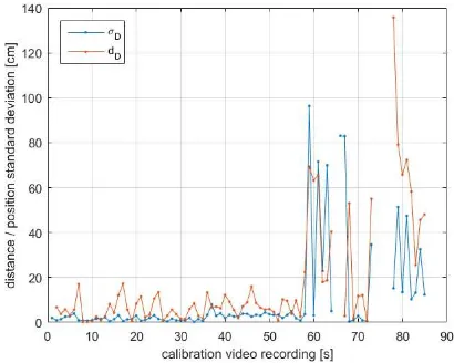
Figure 9: VariationsdDof the estimated vehicle interior driver camera positions over the time of video recording, as well as the position standard deviation of the vehicle interior cameraσD. Plotted over the time the vehicle is standing still during the cali-bration drive. Line between discrete poses drawn for better visu-alization.
the interior vehicle camera, leading to a reduced number of fea-ture matches used for ground control points. Image noise caused by low light in the calibration environment might have also led to different SIFT features in different images, finding no matches to features detected in other images. The higher position standard deviation with values up to 1,000 mm after 60 seconds might be explained as a person enters the car at that time to drive it around within the calibration environment, causing further occlusions of the car seats in the driver camera images. The position differ-ences show a similar trend than the position standard deviations, but with periodic value changes in the first 60 seconds. These observations should be investigated further to conclude on their reason.
A match matrix (showing the number of feature matches between all image pairs) between the a-priori interior images and the vehi-cle interior camera images shows, that there is only a small num-ber of feature matches between the two mentioned image groups. This small number leads to a small number of ground control points for pose estimation, and therefore has negative influence on the position standard deviation. A possible explanation for the small match number is, that the strongly-textured car seats with a high number of possible features can only be seen in a small part of a vehicle interior camera image. A change in the position of this camera should be considered, requiring a trade-off with the occlusion of the field-of-view of the driver.
Median distance Reference distance
Front - Rear 321 cm 323 cm
Front - Driver 81 cm 89 cm
Driver - Rear 359 cm 358 cm
Table 4: Median and reference distances between the vehicle camera positions. Median is obtained from the calculated dis-tances for all time points using the estimated camera positions. The reference distances are obtained from tachymeter measure-ments.
The median distance of the vehicle cameras positions to each other is compared to the distances from tachymeter measurements (table 4). The median is calculated for the distances between the camera positions while the test car is standing still during the cal-ibration drive. As a tachymeter can only measure points on the camera case, but not the projection center, it is assumed, that the projection centers of the used Garmin action cameras are in the middle of the camera case in direction of the optical axis (no fur-ther manufacturer information available). The median distance between the front and rear camera deviates only two centimeters from the reference distance, while the deviation for the distance between front and driver camera is around 10 cm. The smaller deviation between the vehicle environment cameras might be ex-plained, because both camera poses are estimated using the same point cloud as reference information. In opposite, the front and driver camera poses are estimated with different point clouds, and an additional error might be caused by the transformation between the point clouds. The deviation for the driver and rear camera is only one centimeter, but it has to be mentioned, that the distance deviation is smaller than the calculated position standard deviations (figures 8, 9).
6. CONCLUSION
In this contribution, a method for a vehicle camera system cali-bration using unmarked reference points has been proposed. The method can be used for vehicle environment and vehicle inte-rior cameras with no overlapping fields-of-view. It is shown, that point clouds can be obtained for the environment around the ve-hicle as well as for its interior space. Both point clouds can be
connected to each other using a similarity transform with refer-ence points from objects shown in environment images and inte-rior images as well. With a second similarity transformation, the point clouds are transformed into a vehicle coordinate system de-scribing the movement direction of the car using reference points on the wheel rim centers. The poses of both groups of vehicle cameras can be estimated especially when the vehicle is standing still during a test drive using the 3d points of the point clouds as reference information. The proposed method can be seen as suitable for an application in the field of driver intention recog-nition. For this application, the knowledge of the camera poses with a centimeter position accuracy is sufficient for combined in-formation extraction about the traffic situation from vehicle envi-ronment and interior cameras.
For the future, a change of the position of the interior driver cam-era has to be considered. A position with a better view on well-textured surfaces like car seats might facilitate the feature extrac-tion and therefore increase the accuracy of the estimated poses. Further research can also be done on validation of the estimated poses in long-time vehicle drives.
REFERENCES
Abraham, S. and Förstner, W., 2005. Fish-eye-stereo calibration and epipolar rectification. ISPRS Journal of Photogrammetry and Remote Sensing 59(5), pp. 278 – 288.
Brown, D. C., 1971. Close-range camera calibration. Photogram-metric Engineering 37(8), pp. 855–866.
Conrady, A. E., 1919. Decentred Lens-Systems. Monthly notices of the Royal Astronomical Society.
Cordts, M., Omran, M., Ramos, S., Rehfeld, T., Enzweiler, M., Benenson, R., Franke, U., Roth, S. and Schiele, B., 2016. The cityscapes dataset for semantic urban scene understanding. CoRR.
Esquivel, S., Woelk, F. and Koch, R., 2007. Calibration of a multi-camera rig from non-overlapping views. In: Proceedings of the 29th DAGM Conference on Pattern Recognition, Springer-Verlag, Berlin, Heidelberg, pp. 82–91.
Fraser, C., 2013. Automatic Camera Calibration in Close Range Photogrammetry. Photogrammetric Engineering and Remote Sensing 79(4), pp. 381–388.
Geiger, A., Lenz, P. and Urtasun, R., 2012. Are we ready for autonomous driving? the kitti vision benchmark suite. In: Con-ference on Computer Vision and Pattern Recognition (CVPR).
glassBYTEs.com, 2015. Belron’s u.k. company autoglassR launches adas calibration protocol. Website, http://www.glassbytes.com/2015/10/belrons-u-k-company-autoglass-launches-adas-calibration-protocol/. 2017-01-30.
Gruen, A. and Beyer, H. A., 2001. System Calibration Through Self-Calibration. Springer Berlin Heidelberg, Berlin, Heidelberg, pp. 163–193.
Hanel, A. and Stilla, U., 2017. Calibration of a vehicle camera system with divergent fields-of-view in an urban environment. In: 37. Wissenschaftlich-Technische Jahrestagung der DGPF.
Häming, Klaus, P. G., 2010. The structure-from-motion recon-struction pipeline – a survey with focus on short image sequences. Kybernetika 46(5), pp. 926–937.
Jain, A., Koppula, H. S., Raghavan, B. and Saxena, A., 2015. Know before you do: Anticipating maneuvers via learning tem-poral driving models. CoRR.
Kazik, T., Kneip, L., Nikolic, J., Pollefeys, M. and Siegwart, R., 2012. Real-time 6d stereo visual odometry with non-overlapping fields of view. In: 2012 IEEE Conference on Computer Vision and Pattern Recognition, pp. 1529–1536.
Koenderink, J. J., Van Doorn, A. J. et al., 1991. Affine structure from motion. JOSA A 8(2), pp. 377–385.
Lowe, D. G., 1999. Object recognition from local scale-invariant features. In: Proceedings of the International Conference on Computer Vision-Volume 2 - Volume 2, ICCV ’99, IEEE Com-puter Society, Washington, DC, USA.
Nikon, 2007. Nikon / imaging products / specifications - nikon d3. Website, http://imaging.nikon.com/lineup/dslr/d3/spec.htm. 2017-01-31.
OpenCV, 2017. Camera Calibration and 3D Reconstruction. Website, http://opencv.org. 2017-01-30.
Pemble, C. A., 2017. Garmin VIRB Ultra 30 Technical Specifica-tions. Website, http://www8.garmin.com/automotive/pdfs/VIRB-Ultra30-specs.pdf. 2017-01-29.
Samuelsson, H., 2017. Vision 2020 | Volvo Cars. Web-site, http://www.volvocars.com/intl/about/our-stories/made-by-sweden/vision-2020. 2017-01-30.
Schneider, C.-T., Bösemann, W. and Godding, R., 2017. AICON 3D Systems GmbH. Software Aicon 3d Studio.
Schneider, J. and Förstner, W., 2013. Bundle adjustment and sys-tem calibration with points at infinity for omnidirectional camera systems. Z. f. Photogrammetrie, Fernerkundung und Geoinfor-mation 4, pp. 309–321.
Schwalbe, E., 2005. Geometric modelling and calibration of fish-eye lens camera systems. In: Proceedings 2nd Panoramic Pho-togrammetry Workshop, Int. Archives of PhoPho-togrammetry and Remote Sensing, pp. 5–8.
Sturm, P. F. and Triggs, B., 1996. A factorization based algo-rithm for multi-image projective structure and motion. In: Pro-ceedings of the 4th European Conference on Computer Vision-Volume II - Vision-Volume II, ECCV ’96, Springer-Verlag, London, UK, UK, pp. 709–720.
Volkswagen, 2017. Technische Zeichnungen - VW Nutzfahrzeuge. Website, http://www.volkswagen-
nutzfahrzeuge.ch/de/beratung—verkauf/auf–und-umbauten/technische-zeichnungen.html. 2017-01-29.
Volvo, 2014. Sensor for Driver State Estimation. Image, https://www.media.volvocars.com/global/en- gb/media/pressreleases/140898/volvo-cars-conducts-research- into-driver-sensors-in-order-to-create-cars-that-get-to-know-their-driv. 2017-01-24.
Wu, C., 2007. A GPU implementation of Scale Invaraint Fea-ture Transform (SIFT). Website, http://cs.unc.edu/ ccwu/siftgpu. 2017-01-10.
Wu, C., 2011. VisualSFM: A Visual Structure from Motion Sys-tem. Website, http://ccwu.me/vsfm/. 2017-01-10.