CFD Modeling Of Waste Heat Recovery On
The Rotary Kiln System in the Cement
Industry
Novia Novia1,2, Muhammad Faizal1,2, Septa Liana2
1
Department of Chemical Engineering, Faculty of Engineering, University of Sriwijaya, Inderalaya, Palembang 30662, Indonesia.
2
Department of Chemical Engineering, Program Pascasarjana, University of Sriwijaya
Email: [email protected]
ABSTRACT
The cement production process is one of the most energy and cost intensive in the world. In order to produce clinker, a cement industry requires the substantial energy consumption. About 70% of energy consumption lies on the unit of rotary kiln system. The higher amount of energy consumption is due to the lack of work efficiency tools leading the waste heat. This reserach was focus on modeling of the waste heat recovery in the rotary kiln system using CFD. Analysis of mass and energy balance was used to determine the sources of heat loss from kiln system. The results showed that the distribustion of the input heat to the system is a good agreement with the output energy and gave the significant insights oft the reasons for the low overall system efficiency. The system efficiency is obtained of 53 %. The major heat loss sources have been determined as kiln exhaust (21.88% of total input), cooler exhaust to stack (9.62 % of total input) and heat loss astemated as heat from kiln surface (13.54 % of total input). The amount of heat energy can be absorbed by air amounted to 163,080 Kcal / hour and can be used as air for combustion of fuel. Based on data calculation, the amount of coal can be saved amounted to 738 kg / day.
INTRODUCTION
to make mass and energy balance of the kiln system. They discussed several systems to recover waste heat energy on the kiln system for the use of waste heat recovery steam generator (WHRSG), pre-heating the raw materials, and heat recovery. These applications were calculated to produce how much energy and production cost savings that can be done. Kabiret.al.(2009) applied the basics theory of waste heat recovery on the existing cement industry in Nigeria. Their results showed that the electrical energy can be saved for 42.88 Mw / year and reducedthe emissions of green house gasses of about 14.10%.
The cement industry absorbs the large amount of energy. The energy
sources come from the fuel, electricity, explosives, etc. Heat energy derived from
fuel combustion in the kiln is the largest energy demand which reach more than 75 % of the total energy requirements. Loss a number of energy consumption in the cement industry is usually caused by a lack of work efficiency. A number of energy produced from the fuel is not fully utilized in the process. There are a number of heats lost from the system through the hot exhaust gas, cooling stack and kiln wall surface. In this work, the heat recovery was emphasized on the kiln wall surface.
Kiln is a tube-shaped device where the burning process is occurred by fire. It is designed to maximize the efficiency of heat transfer from the combustion of fuel at the higher temperature. The high temperature leads the temperatures around the kiln is also further increased and dumped into the environment. Heat around the kiln temperature is called as a waste heat. Waste heat can be used as a source of energy. It can be recovered for saving of the production cost.
Mass and energy balance was made to calculate amount of heat lost from the kiln system and analyze the balance sheet to determine sources of heat loss from the system. Amount of heatwas used as waste heat recovery from the system for several purposes such as pre-heating of fuel and raw materials, and the steam generator so that the total system energy consumption can be reduced.
The objective of this study is to investigate the waste heat recovery in a cement company. It provides a concept that can be useful for a cement company in conducting of energy savings for the production. It can also reduce greenhouse gas emissions generated at the same time reduce production costs. The advantage of the hot exhaust air flowing through the kiln wall is applied as a fuel in the pre-heater to burn coal.
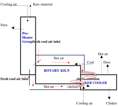
UTILIZATION OF FLUE GAS FROM THE ROTARY KILN SYSTEM CONCEPT
Cement production process requires the substantial energy which reach 4 GJ per ton. In the theory, the production of one ton of clinker requires 1.6 GJ heat
(Liu et.al., 2004). However, the average energy consumption of cement
consumption of other countries could reach 5 GJ/ton. For example, a manufacturer of clinker factory in China requires an average energy consumption
of 5.4 GJ / ton (Khuranaet.al, 2004). Based on these data, it can be concluded that
there are a number of heats lost from the system. Amount of the excess energy is can be utilized potentially as a form of work efficiency tools.
Ideally, all of the heat injected into a kiln or furnace should be used entirely for heating the load or stack. However, in practice, the number of heat is lost in several ways such as loss of exhaust gas, loss of water content in the fuel, the loss due to hydrogen in the fuel, the loss through the opening in the furnace, the loss of the furnace wall / surface, and the other losses. The existence of the heat losses caused the lack of efficiency in the performance of the kiln. Therefore, it is important to optimize the thermal efficiency of the kiln so that the heat loss can be utilized as an energy source using Waste Heat Recovery (WHR).
To determine how many heats can be recovered from the equipment or a system, the important thing to do is to make the analysis of mass balance and energy balance in the system. The objective is to calculate the amount of energy lost from the system and analyze the amount of energy that can be utilized.The energy lost from this system can be recovered as a source of energy for other processes. The manufacturing process in a Cement company produced large amounts of waste heat generated from the kiln or furnace. Waste heat is generated by fuel combustion or chemical reactions. It is then purged into the environment and not used any more for the purpose of economical.
At the beginning of the cement manufacturing process, the mixture of cement materials pass through the stages such as mining materials, weighing, drying. Then, itis accompanied by the destruction of materials, combustion, cooling, and grinding. Finally, it was stored in the reservoir which is called by Silo. These stages produce high quality cement with a high selling price. The process that can determine the outcome of a cement product is the burning process in the furnace turn which is called by a kiln. It is used to burn material that has
been destroyed by heat in the raw mill kiln. The temperature reached 1400 0C –
Cooling air Raw material
Dust
Pre- Heater
Groupfresh cool air inlet
Hot air Hot air
Coal Dust
ROTARY KILN
fresh cool air inlet air combustion
CLINKER COOLER
Hot air clinker
Cooling air Clinker
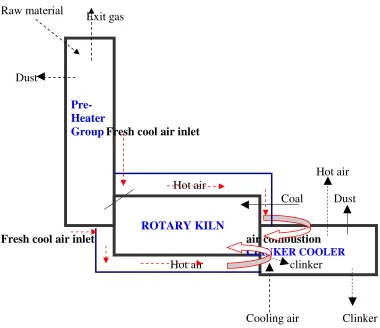
Figure 1 Utilization of Flue Gas from the rotary kiln system concept
RESULTS AND DISCUSSIONS
A. Data Collected
The data was taken from the PT. Xwhich is collected during six months within June to December 2010.The dataapplied in this study is the averaged values. The data collected in the forms of:
• data of production process,
• installed equipment design follows the pattern of operation,
• average production data for six months
• consumption of raw materials and products
• energy and fuel consumption
The data was analyzed in the form of mass and energy balance. Profiles of thermal energy use were made to obtain the thermal balance analysis of equipment such as the kiln combustion chamber and pre-heater / pre-calciner. For the calculation of mass and energy balance requiring data such as: fuel, raw materials and products, combustion air flow rate, wall temperatures, ambient temperatures and others.
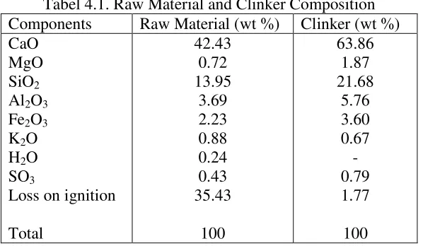
The plant uses a dry process with a series of cyclone type pre-heater and an incline-kiln. The kiln is 4,5 diameter and 75 m long. The average daily production capacity is 4200 ton per day, and the specific energy consumption has been estimated to be 760 kcal/kg clinker. The compositions of raw material, clinker components and their percentages, and fuel were determined using standard procedures; the results are presented in Table 4.1 and Figure 4.2.
Tabel 4.1. Raw Material and Clinker Composition
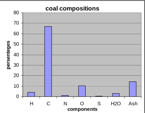
Figure 4.1 Coal Compositions
Based on the coal composition, the net heat consumption value is found of 890 kcal / kg clinker. The coal used in PT. X has acalorific valuerangesbetween5300 - 6400kcal/kgasthe primaryfuelinthe production process. The amountof coalrequired totally isabout 25.5tonsperhourthat consist of
10.3tonsperhourforkiln requirementsand 15.2tonsperhourfor thecalciners.
Dataanalysistechnicalforcoalhas been shown in table 4.2.
Table 4.2 Technical Analysis Coal (%)
Fixed Carbon 63.86
Volatile Matter 43.50
Ash 10.14
Sulfur 0.50
Moisture 12.00
Caloric Value Coal 6,200 kcal / kg
Pulverized Coal Fineness & Moisture:
- Residue >90 U 17
- Residue >200 U 0.2
- Moisture 3
Combustion of coal provides the heat required for the reactions in the rotary kilns. Generally, it was operated on low fuel consumption without affect the quality of clinker produced. This could be achieved through an understanding on how the fuel is burnt and how efficient is utilised during burning. However,
coal compositions
0 10 20 30 40 50 60 70 80
H C N O S H2O Ash
components
p
e
rs
e
n
te
g
e
energy audit is the technique used to evaluate the thermal energy performance of the kiln system (Kabir, et.al, 2009).
B. Analysis of Mass and Energy Balance
Mass and energy balance analysis is a technique used to evaluate the presence of heat energy from a process unit (rotary kiln system). This is a quantitative analysis of the overall calculation of a unit of all incoming materials, materials that come out; the material accumulated and discarded materials from the system. This calculation can show clearly the profile of mass and energy of a unit in an industrial process.
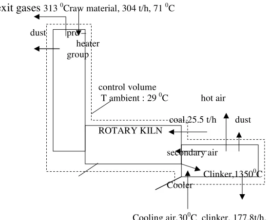
General process flow diagram used in all mass and energy balance analysis to facilitate this research, clearly described all the events that occurred in the process unit observed. The flow chart is a visual representation that shows all the flow of materials either enters or exit devices, along with composition data
from a mixture of materials flow. The flow diagramofthe
kilnsystemisasfollowing:
exit gases 313 0Craw material, 304 t/h, 71 0C
dust pre – heater group
control volume
T ambient : 29 0C hot air
coal,25.5 t/h dust ROTARY KILN
secondary air
Clinker,13500C Cooler
Cooling air,300C clinker, 177.8t/h, 120 0C
Figure 4.2Flow diagram of rotary kiln system
Material and heat balances around the control volume were performed on
a basis of 1kg clinker. Datum temperatures of 0 0C was taken, the quantity of
energy and sensible heat of the different streams into and from the control volume were calculated. For the balances, the following streams data were required:
- feed rate of raw material
- fuel and air entering the system
- clinker discharge rate
- Kiln exit gases leaving the system.
The data can be obtained from the plant records, while other relevant data for the analysis can be evaluated. The result of the materialbalance forthe kilnsystemhas been describedin figure 4.3.
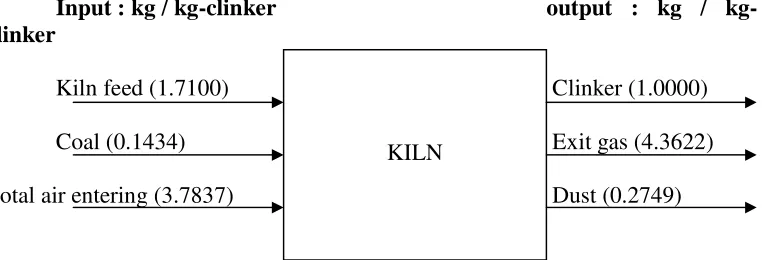
Input : kg / kg-clinker output : kg / kg-clinker
Kiln feed (1.7100) Clinker (1.0000)
Coal (0.1434) Exit gas (4.3622)
Total air entering (3.7837) Dust (0.2749)
Figure 4.3 Material Balance of the Kiln system overall
Based on the results of the above material balance, we can see that 77% of the output mass is the mass of the exit gas. A large amount of mass has a large enough energy unused. The amount of energy contained in the mass we can see in the energy balance.The gascameoutof thekilnsystem, theexhaustgasescame outof thepre-heater and thegasalso producedin thestack. Thetemperatureof these gases
werehighly enough which is about3130C. This hightemperatureishighly
potentialas anenergy source.
In order to analyze the kiln system thermodynamically, the following assumptions were made:
1. Steady state working conditions.
2. The change in the ambient temperature is neglected.
3. Cold air leakage into the system is negligible.
4. Raw material and coal compositions do not change.
5. Averaged kiln surface temperatures do not change.
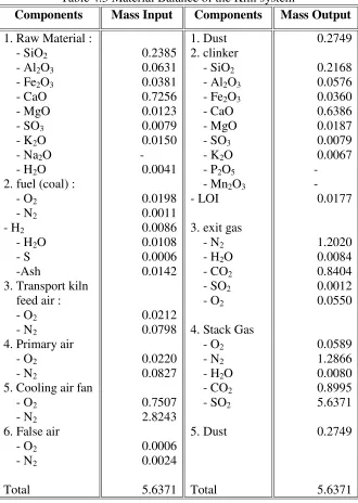
Table 4.3 Material Balance of the Kiln system
Components Mass Input Components Mass Output
1. Raw Material :
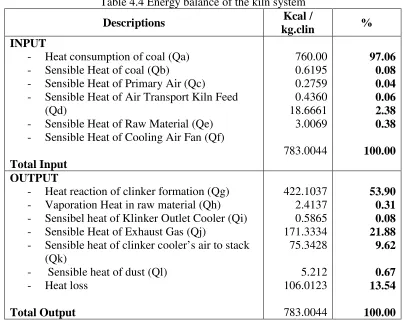
Table 4.4 Energy balance of the kiln system
Descriptions Kcal /
kg.clin %
INPUT
- Heat consumption of coal (Qa)
- Sensible Heat of coal (Qb)
- Sensible Heat of Primary Air (Qc)
- Sensible Heat of Air Transport Kiln Feed
(Qd)
- Sensible Heat of Raw Material (Qe)
- Sensible Heat of Cooling Air Fan (Qf)
Total Input
- Heat reaction of clinker formation (Qg)
- Vaporation Heat in raw material (Qh)
- Sensibel heat of Klinker Outlet Cooler (Qi)
- Sensible Heat of Exhaust Gas (Qj)
- Sensible heat of clinker cooler’s air to stack
(Qk)
Table 4.4 showedthat the coal combustion as a fuel generated of 97.06% (760 Kcal / Kg clinker) of the total heat input to the unit. It can be seen from the table that the total energy used in the process is about 783.0044 Kcal / kg clinker. The sensible heats with the raw material, fuel, air entering the coolers, and organic carbon (feed component) heat contents are relatively small. The total sensible heats with the streams are about 2.94% of material streams. The energy balance given in table indicates the relatively good consistency between the total heat input and total heat output.The distribution of heat losses to the individual components exhibits reasonably good agreement between some other key plants reported to the previous study.
C. Energy Saving Opportunities for Dry Kiln System Baturaja Cement Plant
The low energy efficiency established the potential energy saving opportunities in the unit. Relevant thermal energy recovery and conservation concept for the kiln system are proposed and studied. Successes for using the concepts are expressed in terms of financial and environmental benefits. Some application that can used as recovery and conservation measures such as: raw material drying at the raw mill; waste heat recovery from kilns exit gases using steam generator; and klin shell heat losses reduction.
1. Heat Recovery from The Kiln System
The overall system efficiency can be defined by η = Qg / Qtotal input =
422.103 / 783.0044 = 0.53 (53%). This efficiency is relatively low. Some kiln systems that operate at full capacity also has an efficiency of 55% based on the current dry process methodology. The overall efficiency of the kiln system can be improved by recovering some of heat losses. There are a few major heat loss sources that would be considered for heat recovery. Heat losses produced by kiln consist of the exhaust gas (21.88%), hot air from cooler stack (9.62%), heat loss that estimated as heat of kiln surface (13.54%).
2. Waste Heat Rocovery Concept
The hot kiln suface is another significant heat loss source, and the heat loss trough convection and radiation dictates as waste energy 96.41 Kcal. On the other hand, the use of a secondary shell on the kiln surface can significantly reduce this heat loss. For the current rotary kiln, Rkiln = 2.25 m, and a radius of Rshell = 2.65 m can be considered. Since the distance between the two surface is relatively small (40cm), a realistic estimation for the temperature of the secondary shell can be made.
Raw material
Dust
Pre- Heater
Group Fresh cool air inlet
Hot air Hot air
Coal Dust
ROTARY KILN
Fresh cool air inlet air combustion
CLINKER COOLER
Hot air clinker
Cooling air Clinker
Figure 4.4 Utilization of Flue Gas from the rotary kiln system concept
Based on the data obtained, the amount of energy that can be absorbed by air amounted to 163,080 Kcal / hour. This energy is obtained from the results of heat transfer that occurs from the surface of the kiln into the air. Air containing the amount of energy was used as combustion air for fuel. Based on data calculation, the amount of coal can be saved of about 738 kg / day.
D. CFD Analysis
CFDis asimulation offluid flow systemusingamodeling/ formulationof physicalproblems
whicharesolvedmathematicallyandanumericalmethodofformation
ofnumericalparameters, grid, and thesolver. CFDuse several multiplesolversin the problemsolving.One of thesolversusedisFluent6.3. This softwareis oneofthe
computer programsthatcan beusedinmodelingfluid flow, heattransfer,
Thisstudy hasusedCFD analysistoshowthe flow ofheatabsorbedbyairfrom
thesurface ofthe kilnwall. In addition,byusing
afluentwecansimulateseveralconditionsthat occurinthekiln. Kilnhasa
diameterof4.5mby75mlong. It cangenerateheataroundthe kilnwallaround600 0K.
The geometry of kilnwasmadebyGambitprocessor, and then thedata was exported into solver.
The description of process as following: airflowsattheinlet ofthe shellandabsorbsthe heatalong thekiln wall. Whilethe kilnwall isin contactwiththe surface oftheheat,theaircomes outof theshelloutletfor the higher temperature. Velocity of airwas varied of 3m/s, 6m/s, 9m/sand15m/s.Figure4.5 and figure 4.6 describe thedistribution ofairtemperatureonthe inletand outlet ofthe shell.From these figures we can see that the airtemperatureschangeinthekilnshell. The highest temperature was obtained at the kiln wall. This is due to the heat absorbed at this condition.
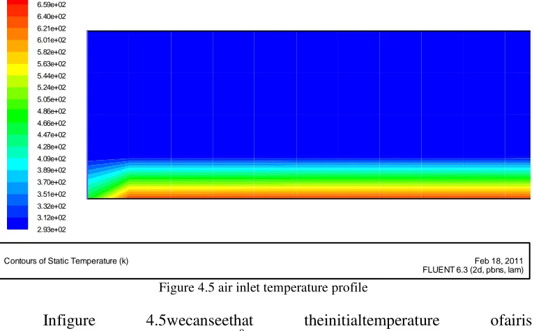
Figure 4.5 air inlet temperature profile
Infigure 4.5wecanseethat theinitialtemperature ofairis
equaltotheambienttemperatureof 2930K. The blue colorin the figureshows the
lowest temperature which is at the shell wall and the red color shows the highest one which is at the kiln wall. Atthebeginning, when the air isdischargedintothe kilnshell,temperature was not significantlychanged.
Contours of Static Temperature (k)
FLUENT 6.3 (2d, pbns, lam) Feb 18, 2011
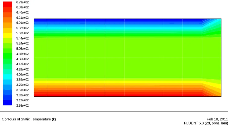
Figure 4.6 air outlet temperature Profil in outlet shell
Figure 4.6 illustrates the condition of the air temperature at the shell kiln outlet. It is shown that the temperature decreased from the kiln wall to the shell wall that is indicated by the changing of colors. This figuredescribesthe temperature changing occursfromthe redcolorsto become the blue one. Any color changes that occur identified that there was a change in temperature. We also can
see that the air temperature at the inlet shell of 2930K (blue color) to5180K (red
color).
Figure 4.7 Temperaturedistributionsat eachpositiononthe kilnshellwidth
Contours of Static Temperature (k)
FLUENT 6.3 (2d, pbns, lam) Feb 18, 2011
The distribution ofairtemperatureinside of thekilnshellcan beseenin thechartabove. Y-axis representsthe position ofairflowatsomepointon theradius ofshell wall. X-axisrepresentsthe airtemperatureatthe length of thekilnshell. For
x=0(inlet),the temperaturenear the kiln wall is about 3650K, then the
temperaturedecreased constantly ofabout 293oK withthe positionyof0.1 till
0.4(thekiln wall). Forx=10m, 20m, 30mand37.5m(distance from theinlet) the
airtemperatureof about435oK and the decreasing of temperature is similar atthe
position ofy=0.1mtoaty=0.3 m. Finally, at theposition of y=0.4m and the
temperaturedecreasedto become 293oK.Underthese
conditionswecanseethatthemosteffectiveheat absorptionislocatedatpositiony=0
toy=0.1.
Figure 4.8Distribution oftemperaturealong thekilnshell in v = 3m/s, 6m/s, 9m/s,15m/s
Figure 4.8 indicates that atvariousof air velocities, the profile of
temperatures are similar. Thereforeone oftheanalyzeddatais expectedas
arepresentative of theoveralloperating conditions. It can be seen that the reducing
of air velocity caused the temperature increasing. Based on
thedataresultsobtainedin figure4.8,the smaller of theairvelocity whichisused, the higher of heatcan beabsorbedbyair.
Static Temperature
FLUENT 6.3 (2d, pbns, lam) Feb 08, 2011
Position (m) (k)
TemperatureStatic
40 35 30 25 20 15 10 5 0 6.00e+02
5.50e+02
5.00e+02
4.50e+02
4.00e+02
3.50e+02
3.00e+02
2.50e+02 v=3ms-1
CONCLUSION
The distribustion of the input heat energy to the system components showed good agreement between the total input and output energy and gave significant insights about the reasons for the low overall system efficiency. According to the results obtained, the system efficiency is 53 %. The major heat loss sources have been determined as kiln exhaust (21.88% of total input), cooler exhaust to stack (9.62 % of total input) and heat loss astemated as heat from kiln surface (13.54 % of total input). The amount of heat energy can be absorbed by air amounted to 163,080 Kcal / hour and can be used as air for combustion of fuel. Based on data calculation, the amount of coal can be saved amounted to 738 kg / day.
REFERENCES
Anderson, John D. (1995), Computational Fluid Dynamics: The Basics With
Applications, Science/Engineering/Math, McGraw-Hill Science,
ISBN0070016852
Antee U., et.al.Cement manufacturing using alternative fuels and advantages of
process modelling. Presented at R’2002 Recovery, Recycling, Re-Integration, Geneva, Switzerland, Available from: http://www.R2002.com, 12–15 February 2002.
Barton, Allan F.M. 1979. Resource Recovery and Recycling.Murdoch
University.Western Australia.
Bindar,Y., et.al. 2009. Modeling Rotary Kiln in The Production of Sponge Iron,
Indonesian National Seminar of Chemical Engineering. Bandung. Indonesia.
Distantina, Sperisa. 2010. Modul of Mass and Energy Balance. Chemical
Engineering Department SebelasMaret University Surakarta
Indonesia.Surakarta.
EnginT,and Vedat A. 2004. Energy auditing and recovery for dry type cement
rotary kiln systems: a case study. Energy Converts Manage.University of Sakarya.Turkey.
Engin T.1997.Thermal analysis of rotary kilns used in cement plants. First
Mechanical Engineering Congress (MAMKON’97), Istanbul Technical University, TURKIYE, 4–6 June 1997, p. 29–35 [in Turkish].
Felder, R. and Rousseau,R. 1986. Elementary Principles of Chemical
Kabir,G., et.al. 2009. Energy audit and Conservation Opportunities for
Pyroprocessing Unit of A Typical Dry Process Cement
Plant.AbubakarTafawaBalewa University.Nigeria.
Kamal K. 1997.Energy efficiency improvement in the cement industry.Seminar on
Energy Efficiency, organized by ASSOCHAM - India and RMA-USA.
Khurana S.,et.al. Energy balance and cogeneration for cement plant.
ApplThermEng2002;22:485–94.
Nezekiel,ST. 2010. Heat Transfer Process in The Rotary Kiln Wall on
Indocement Tunggal Perkasa company. Gunadarma University.Indonesia.
Paradita, Arga S. 2009. Outlook IndustriSement 2010.Asia Securities, Indonesia.
Peray KE.2003.Cement manufacturer’s handbook. New York, NY: Chemical
Publishing Co., Inc.; 1979. Cengel YA.Heat transferA practical approach. 2nd ed. New York, NY: McGraw-Hill.
Purwanto, et.al.Implementation of Cleaner Production in The Small Medium
Industries to Enhance Energy Efficiency and Reduce The
Waste.Diponegoro University.Semarang. Indonesia.
United Nation Environment Programme. 2006. Waste Heat Recovery. London,
England.
United Nation Environment Programme. 2006. Furnace and Refaractories.