STRUCTURED LIGHT BASED 3D SCANNING FOR SPECULAR SURFACE BY THE
COMBINATION OF GRAY CODE AND PHASE SHIFTING
Yujia Zhanga, Alper Yilmaza,∗ a
Dept. of Civil, Environmental and Geodetic Engineering, The Ohio State University 2036 Neil Avenue, Columbus, OH 43210 USA - (zhang.2669, yilmaz.15)@osu.edu
Commission III, WG III/1
KEY WORDS:Structured Light, 3D Scanning, Specular Surface, Maximum Min-SW Gray Code, Phase Shifting
ABSTRACT:
Surface reconstruction using coded structured light is considered one of the most reliable techniques for high-quality 3D scanning. With a calibrated projector-camera stereo system, a light pattern is projected onto the scene and imaged by the camera. Correspondences between projected and recovered patterns are computed in the decoding process, which is used to generate 3D point cloud of the surface. However, the indirect illumination effects on the surface, such as subsurface scattering and interreflections, will raise the difficulties in reconstruction. In this paper, we apply maximum min-SW gray code to reduce the indirect illumination effects of the specular surface. We also analysis the errors when comparing the maximum min-SW gray code and the conventional gray code, which justifies that the maximum min-SW gray code has significant superiority to reduce the indirect illumination effects. To achieve sub-pixel accuracy, we project high frequency sinusoidal patterns onto the scene simultaneously. But for specular surface, the high frequency patterns are susceptible to decoding errors. Incorrect decoding of high frequency patterns will result in a loss of depth resolution. Our method to resolve this problem is combining the low frequency maximum min-SW gray code and the high frequency phase shifting code, which achieves dense 3D reconstruction for specular surface. Our contributions include: (i) A complete setup of the structured light based 3D scanning system; (ii) A novel combination technique of the maximum min-SW gray code and phase shifting code. First, phase shifting decoding with sub-pixel accuracy. Then, the maximum min-SW gray code is used to resolve the ambiguity resolution. According to the experimental results and data analysis, our structured light based 3D scanning system enables high quality dense reconstruction of scenes with a small number of images. Qualitative and quantitative comparisons are performed to extract the advantages of our new combined coding method.
1. INTRODUCTION
Three-dimensional scanning is an important research in computer vision, which has different applications in various fields such as computer graphics, industrial inspection, reverse engineering, virtual and augmented reality, object recognition, robot naviga-tion and manufacturing.
The existing 3D scanning techniques are traditionally categorized into contact and non-contact techniques. The contact 3D scan-ning techniques have a long history, but the performance is slow and the equipments are expensive. Besides, contact techniques always need to touch the object, which limits the applications. Then, non-contact is studied to overcome these problems and has developed recent years. The non-contact techniques are classified into two categories, active and passive. In passive approaches, the scene is imaged from two or more points of view and the correspondences between them are computed. With the calibra-tion and correspondences results, the point cloud is generated by stereo triangulation. The major problem for this passive approach is finding the correspondences in the presence of textureless sur-faces since it is a sparse reconstruction based on the texture of the object (Kawasaki et al., 2008). Therefore, active approaches are studied to cope with the limitations in finding correspondences. Structured light based 3D scanning is one of these active ap-proaches, which creating correspondences to every pixel in the image by specific codewords. Comparing with most expensive 3D scanners, structured light based 3D scanning is one of the most wildly used and low cost techniques for dense 3D recon-struction.
The structured light 3D scanning system comprises a digital
pro-∗Corresponding author
jector, which is viewed as an inverse camera, and a digital camera. So the calibration procedure of the projector-camera stereo sys-tem is similar to the conventional stereo-vision syssys-tem (Zhang and Huang, 2006). The projector is used to project certain pat-tern on the scanned surface and the projected image sequences are captured by the camera. Correspondences are estimated in the decoding process, which is based on the properties of the de-signed codeword.
Paper (Salvi et al., 2010) presnets an up-to-date review and a new classification of the existing coding strategies used in active struc-tured light 3D scanning. The classification is depending on the strategy used to create the pattern, and qualitative and quantita-tive experimental results are given to analysis the feasibility and accuracy of different techniques. The classification and compari-son will be discussed in details in Section 2.
Another problem for structured light techniques is that it requires environment with well light condition. It is assumed that the scanned surface receives illumination directly from the light source. However, indirect or global illumination effects on the surface, such as subsurface scattering and interreflections, will raise the errors when finding the correspondences. So the performance of structured light 3D scanning strongly depends on the shape and material properties of the scanned surface.
are conducted to compare our method with the state of the art, which shows that our new combined coding method outperforms conventional gray code, Gupta code ensemble and micro phase shifting method.
2. RELATED WORK
Structured light 3D scanning has been studied for about 40 years (Will and Pennington, 1971) and the researches focus on reducing the computation time and increasing the depth resolution. The coded structured light (CSL) system is based on the projection of one or a sequence of patterns. The existing pattern projec-tion techniques can be classified into discrete coding methods and continuous coding method (Salvi et al., 2010).
The discrete coding methods are based on spatial or temporal multiplexing techinuqes. For spatial multiplexing, the codeword of specific position is extracted from surrounding features. There are three different coding strategies in spatial multiplexing tech-niques: De Bruijn pattern, non-formal coding and M-arrays. De Bruijn sequences contains both striped and multi-slit patterns and the position is extracted by distinguish the color of the stripes in the same window. Different De Bruijn based patterns are pro-posed by Boyer and Kak (Boyer and Kak, 1987), Monks et al. (Monks et al., 1992), Salvi et al. (Salvi et al., 1998) and Pages et al. (Pages et al., 2004) (Pags et al., 2005). Non-formal encod-ing summarizes all the techniques non-orthodox codification, in-cluding one-axis and two-axis coding methods. Forster (Forster, 2006) and Fechteler and Eisert (Fechteler and Eisert, 2008) pro-posed one-axis coding methods all based on De Bruijn techniques. Tehrani (Tehrani et al., 2008) used color slits patterns and is taken from two camera views. Maruyama and Abe (Maruyama and Abe, 1989) presented a two-axis coding method with the length of the slits and their position. Another solution developed by Kawasaki et al. (Kawasaki et al., 2008) is also based on stripe lengths in both horizontal and vertical directions. M-arrays was first presented by Etzion (Etzion, 1988), which are random arrays of dimensionsr×vand a sub-matrix of dimensionsn×mappears uniquely in the whole pattern. Different from De Bruijn patterns, M-arrays are designed in two-dimensional space, which increas-ing the decodincreas-ing accuracy. More M-array based patterns are pro-posed by (Griffin et al., 1992), (Morano et al., 1998), (Pages et al., 2006) and (Albitar et al., 2007).
Time multiplexing methods project successive patterns onto the scanned surface and apply coarse-to-fine paradigm to compute the correspondences of significant bit until all patterns have been projected. There are several approaches in discrete time mul-tiplexing, for instance, temporal binary codes, temporal n-ary codes, temporal hybrid codes and shifting methods. The temporal binary codes were firstly proposed by Posdamer and Altschuler (Posdamer and Altschuler, 1982) in 1982, which is almost the earliest coded structured light method. In this sytem, a sequence of patterns with black and white stripes were projected onto the surface. The length of the codeword was given by2m
bits with m projected patterns. Then a coarse-to-fine strategy was ap-plied to extract the correspondences for each stripe. Gupta et al. (Gupta et al., 2012) designed binary structured light patterns that are resilient to individual indirect illumination effects. The pat-terns combines conventional gray codes, maximum min-SW gray codes, logical XOR-02 codes and logical XOR-04 codes by using simple logical operations and specific combinatorial technique. One kind of the temporal n-ary codes was introduced by Caspi et al. (Caspi et al., 1998). It is a color based pattern wherenm
stripes were coded in RGB space. Ishii et al. (Ishii et al., 2007) proposed a system, which combined temporal and spatial coding. Shifting methods in discrete time multiplexing is popular recently
because that the shifting techniques can achieve sub-pixel accu-racy to obtain dense reconstruction. There are several approaches for shifting methods, such as Sansoni et al. (Sansoni et al., 2000), Guhring et al. (Guehring, 2000) and Zhang et al. (Zhang et al., 2002). According to the review and comparison among the exist-ing techniques (Salvi et al., 2010), Guhrexist-ing method achieves the most accurate result. This means that locating based on a robust gray code with sub-pixel accuracy leads to better performance than using pixel accuracy (in the case of Posdamer method (Pos-damer and Altschuler, 1982)).
The continuous coding methods is a set of patterns with contin-uous variations on intensity or color in one or two axis, includ-ing phase shiftinclud-ing methods, frequency multiplexinclud-ing methods and continuous spatial grading methods. The phase shifting methods project sinusoidal patterns onto a surface and find the correspon-dences based on decoding the unique value of every point. The phase shifting methods contain single phase shifting and multiple phase shifting, both of them are in time multiplexing. The phase shifting technique is firstly proposed by (Srinivasan et al., 1985). Other single phase shifting approaches are introduced in the fol-lowing years, such as (Wust and Capson, n.d.) and (Guan et al., 2003). Multiple phase shifting methods use more than one fre-quency in phase shifting to cope with the uncertainty in phase unwrap process. Famous multiple phase shifting methods are (Gushov and Solodkin, 1991) and (Pribani´c et al., 2009). For the frequency multiplexing methods, phase decoding is performed in the frequency domain rather than in the spatial domain, including Fourier transform profilometry and wavelet transform profilome-try. The continuous spatial grading methods group all techniques with codeword for a given position in spatial domain. For in-stance, (Carrihill and Hummel, 1985) proposed a linear grayscale codeword with wedge spread through the vertical axis.
Except the structured light, Kinect is a novel, economical and widely used 3D scanner. Kinect adopts a static spatial encoded IR pattern projected on the surface to obtain the correspondences. However, since Kinect uses infrared or laser camera, which is limited in indoor environment. Therefore, by using natural light, the structured light based 3D scanning still has research value and broader applications.
3. METHOD
3.1 Structured Light 3D Scanning System Setup
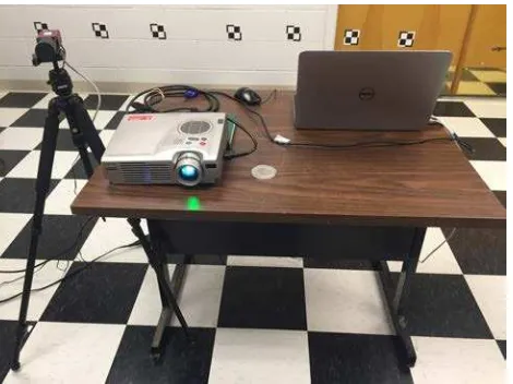
Our structured light 3D scanning system consists of an Epson projector, an AVT GigE camera and a notebook computer as shown in Figure 1. This projector-camera stereo system is economical and easy to be installed. By using this measurement system, we project different kinds of patterns on the object surface and cap-ture image sequences at the same time.
We also developed a structured light 3D scanning software, which fuses the functions of image capture, calibration, decoding and 3D reconstruction together.
3.2 Calibration
Figure 1: Setup of the structured light 3D scanning system
method is that the projector and camera are calibrated together with simple procedures.
The calibration process can be summarized in the following steps:
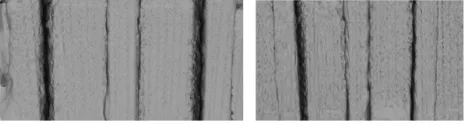
1. In order to calibrate both camera and projector, we project and capture a complete structured light pattern sequence on a planar checkerboard for a number of plane orientations as shown in Figure 2. We require a minimum of three different plane orientations.
Figure 2: Example calibration images: the checkerboard used in the process (left) and the captured image which is projected by one of the gray code (right).
2. Detect corners of the checkerboard for each plane orienta-tion prior to projecting patterns.
3. Decode structured light patterns into projector row and col-umn indices.
4. Compute local homography transformations between the cor-ners computed in step (2) and the decoded pixels obtained from step (3).
5. Use the local homographies from step (4) to translate cor-ners from camera to projector coordinates.
6. Camera calibration: fix a world coordinate system to the checkerboard plane and use Zhang′s method to find camera intrinsic parameters using corners detected in step (2). 7. Projector calibration: fix a world coordinate system to the
checkerboard plane and use Zhang′s method to find pro-jector intrinsic parameters using corners detected from step (5).
8. Stereo calibration: fix camera and projector intrinsic param-eters computed from step (6) and (7). Use world, camera, and projector corner positions from step (2) and (5) to es-timate stereo systems extrinsic parameters (boresight and lever arm).
9. Minimize the total reprojection error by bundle-adjusting all the parameters, including intrinsic and extrinsic parameters.
3.3 Codes Combination
In this paper, we proposed a novel method that combines the max-imum min-SW gray code and micro phase shifting together. The maximum min-SW gray code is used to reduce the indirect illu-mination effects of the specular surface.
The errors in a structured light system are typically caused by long-range (interreflections) and short-range (subsurface scatter-ing) illumination. So the errors depend on the frequency of the projected patterns and the nature of indirect illumination. Some researches show that long-range effects cause decoding er-rors for low-frequency patterns, whereas short-range effects af-fect high-frequency patterns.
According to experiments, we found that the high frequency pat-tern will result in huge decoding errors for specular surface. We also analysis the errors when comparing the maximum min-SW gray code and the conventional gray code, which justifies that the maximum min-SW gray code has significant superiority to reduce the indirect illumination effects.
However, both conventional gray code and maximum min-SW gray code can only achieves pixel-level accuracy. To achieve sub-pixel accuracy, we project high frequency sinusoidal patterns onto the scene simultaneously. But for specular surface, the high frequency patterns are susceptible to decoding errors. Incorrect decoding of high frequency patterns will result in a loss of depth resolution. Therefore, we combine the low frequency maximum min-SW gray code and the high frequency micro phase shifting code, which achieves dense 3D reconstruction for specular sur-face.
3.3.1 Maximum min-SW Gray Code The maximum min-SW gray code is proposed by (Gupta et al., 2013). The maxi-mum min-SW gray code is designed with large minimaxi-mum stripe-width. In the study of combinatorial mathematics, it is available to generate codes with large minimum stripe-widths (min-SW). Then the maximum min-SW gray code is generated by combin-ing 10-bit binary gray code with the min-SW (8 pixels) proposed by (Goddyn, 2003).The code sequence is shown in Figure 3. In comparison, conventional gray code has a min-SW of 2 pixels and maximum min-SW gray code have a maximum stripe width of 32 pixels. Thus, this kind of code is more resistant to reflective or scattering effects than the conventional gray code.
Figure 3: Maximum min-SW gray code.
3.3.2 Micro Phase Shifting The phase shifting pattern is shifted from the previous projection by a factor of2π/N, whereNis the total number of projected patterns. The algorithm for phase shift-ing is shown in Eq. 1.
Ip n(y
p) =Ap+Bpcos(2πf
φyp−2πn/N) (1)
where Ap, Bp
The received intensity values from the projected surface is shown in Eq. 2.
In(x, y) =α(x, y) [A+Bcos(2πfφyp+φ(x, y)−2πn/N)]
(2) The decoding process is conducted to cancel the effect of differ-ent albedoα(x, y)and extract the phase correctly. This process is shown in Eq. 3
φ(x, y) = arctan "PN
n=1In(x, y) sin(2πn/N)
PN
n=1In(x, y) cos(2πn/N)
# (3)
The micro phase shifting is proposed by (Gupta and Nayar, 2012). This method uses patterns so that all the spatial frequencies are within a narrow high-frequency band. All the frequenciesΩ = [ω1, ..., ωF]lie within the bandωm−σ2, ωm+σ2, whereωm
is the mean frequency andσis the width of the band. For ex-ample, whenσis 3 pixels and ωm = 16pixels, the resulting
frequency band is[14.5,17.5].
The phase recovery algorithm withFfrequencies is shown in Eq. refequ:4 and Eq. refequ:5. In this case,F+ 2images is required. One pattern of micro phase shifting code is shown in Figure 4.
Rn(c) =O(c) +A(c) cos(φ1(p) + (n−1)
2π 3 ) (4)
where 1≤n≤3
Rn(c) =O(c) +A(c) cos(φn−2(p)) (5)
where 4≤n≤F+ 2
Figure 4: Micro phase shifting pattern
3.3.3 Combination Technique Our combination technique is similar to (Guehring, 2000). The maximum min-SW gray code and phase shifting code are projected onto the surface together. Since the maximum min-SW gray code is very robust and vary exactly in one bit. The decoding result of this gray code is used to labeling the integer center of every pixel. The sub-pixel locations are obtained in the decoding process of the micro phase shifting patterns.
Thus, the correspondences are detected by the following steps:
1. Decode the maximum min-SW gray code and get the pixel number.
2. Decode the micro phase shifting code and get the sub-pixel correspondences.
3. Attach number labelling from step (1) to the sub-pixel corre-spondences from step (2) to obtain robust correcorre-spondences between projector and camera with high precision.
3.4 Reconstruction
With calibration and correspondences results between projector and camera, we can use the conventional stereo triangulation al-gorithm to generate the point cloud. The principle of stereo tri-angulation is illustrated in Figure 5 (Lanman and Taubin, 2009). We can see that to obtain the 3D point on the scanned surface, we should know the 2D camera pixels and the corresponding 2D projector points. For conventional gray pattern, both column and row correspondences are required to get the 2D projected image coordinates. For our 3D sinusoidal wave gray code, the accurate 2D correspondences can be extracted simultaneously just in pro-jected pattern. Thus, our novel gray code reduces the number of images required to be projected, which can be applied into the real-time dense 3D reconstruction.
Finally, we created a complete 3D model by using Smooth Signed Distance (SSD) surface reconstruction (Calakli and Taubin, 2011). The mesh result fills the holes caused by reflection and preserves the surface details.
Figure 5: Stereo ray-ray triangulation
EXPERIMENTS
Our test set up is shown in section 3.1. The projector resolution is1024×768and the camera resolution is1292×964. We have used the beam model made by specular material, given in Figure 6. Our goal is to estimate the depth of the beam, which is manually measured at 37mm (ground truth). The depth mea-surement is performed by fitting two planes, one for the top and one for the bottom portion of the beam, and measuring the dis-tance between these planes.
Figure 6: Beam made by specular material and its structure
can see that the maximum min-SW gray code outperforms other method, which is robust and more resistant to reflective or scat-tering effects since the holes caused by reflections are filled.
Figure 7: Comparison of point cloud result: conventional gray code (left-top), maximum min-SW gray code (right-top), micro phase shifting code with frequency band around 16 pixels and 5 frequencies (left-bottom), micro phase shifting code with fre-quency bande around 64 pixels and 5 frequencies (right-bottom)
The mesh result of the beam is shown in Figure 8. The compari-son of the mesh results between our method and maximum min-SW gray code method are shown in Figure 9. We can see that the surface obtained from our method is much smoother, which shows outperformance over maximum min-SW method, as well as the phase shifting method.
Figure 8: Mesh result of the beam (two different views)
Figure 9: Comparison between our combined method and maxi-mum min-SW gray code method
4. CONCLUSION
In order to reduces the indirect illumination effects of the specular surface and maintains sub-pixel accuracy simultaneously, we pre-sented an novel code that combines the low frequency maximum min-SW gray code and the high frequency micro phase shifting code. A complete setup of the structured light based 3D scanning system is provided as well. The qualitative and quantitative ex-perimental results verified that the system we developed outper-forms stat-of-the-art methods for scanning specular surfaces. The future work is designing a codeword in multiple directions. This
codeword is similar to radial function, which can be both spatial multiplexing and time multiplexing. The the number of projected images can be reduced in order to achieve real-time structured light 3D scanning.
REFERENCES
Albitar, C., Graebling, P. and Doignon, C., 2007. Design of a monochromatic pattern for a robust structured light coding. In: Image Processing, 2007. ICIP 2007. IEEE International Confer-ence on, Vol. 6, pp. VI – 529–VI – 532.
Boyer, K. L. and Kak, A. C., 1987. Color-encoded structured light for rapid active ranging. IEEE Transactions on Pattern Anal-ysis and Machine Intelligence PAMI-9(1), pp. 14–28.
Calakli, F. and Taubin, G., 2011. SSD: Smooth Signed Distance Surface Reconstruction. Computer Graphics Forum.
Carrihill, B. and Hummel, R., 1985. Experiments with the inten-sity ratio depth sensor. Computer Vision, Graphics, and Image Processing 32(3), pp. 337 – 358.
Caspi, D., Kiryati, N. and Shamir, J., 1998. Range imaging with adaptive color structured light. IEEE Trans. Pattern Anal. Mach. Intell. 20(5), pp. 470–480.
Etzion, T., 1988. Constructions for perfect maps and pseudo-random arrays. IEEE Transactions on Information Theory 34(5), pp. 1308–1316.
Fechteler, P. and Eisert, P., 2008. Adaptive color classification for structured light systems. In: Computer Vision and Pattern Recog-nition Workshops, 2008. CVPRW ’08. IEEE Computer Society Conference on, pp. 1–7.
Forster, F., 2006. A high-resolution and high accuracy real-time 3d sensor based on structured light. In: Proceedings of the Third International Symposium on 3D Data Processing, Visualization, and Transmission (3DPVT’06), 3DPVT ’06, IEEE Computer So-ciety, Washington, DC, USA, pp. 208–215.
Fredricksen, H., 1982. A survey of full length nonlinear shift register cycle algorithms. SIAM Review 24(2), pp. 195–221.
Goddyn, Luis, G. P., 2003. Binary gray codes with long bit runs. The Electronic Journal of Combinatorics [electronic only] 10(1), pp. Research paper R27, 10 p.–Research paper R27, 10 p.
Griffin, P. M., Narasimhan, L. S. and Yee, S. R., 1992. Genera-tion of uniquely encoded light patterns for range data acquisiGenera-tion. Pattern Recognition 25(6), pp. 609 – 616.
Guan, C., Hassebrook, L. G. and Lau, D. L., 2003. Composite structured light pattern for three-dimensional video. Opt. Express 11(5), pp. 406–417.
Guehring, J., 2000. Dense 3d surface acquisition by structured light using off-the-shelf components.
Gupta, M., Agrawal, A., Veeraraghavan, A. and Narasimhan, S. G., 2012. A practical approach to 3d scanning in the presence of interreflections, subsurface scattering and defocus. Interna-tional Journal of Computer Vision 102(1), pp. 33–55.
Gupta, M., Agrawal, A., Veeraraghavan, A. and Narasimhan, S. G., 2013. A practical approach to 3d scanning in the presence of interreflections, subsurface scattering and defocus. Interna-tional journal of computer vision 102(1-3), pp. 33–55.
Gushov, V. I. and Solodkin, Y. N., 1991. Automatic processing of fringe patterns in integer interferometers. Optics and Lasers in Engineering 14, pp. 311–324.
Ishii, I., Yamamoto, K., Doi, K. and Tsuji, T., 2007. High-speed 3d image acquisition using coded structured light projection. In: Intelligent Robots and Systems, 2007. IROS 2007. IEEE/RSJ In-ternational Conference on, pp. 925–930.
Ito, M. and Ishii, A., 1995. A three-level checkerboard pattern (tcp) projection method for curved surface measurement. Pattern Recognition 28(1), pp. 27 – 40.
Kawasaki, H., Furukawa, R., Sagawa, R. and Yagi, Y., 2008. Dy-namic scene shape reconstruction using a single structured light pattern. In: Computer Vision and Pattern Recognition, 2008. CVPR 2008. IEEE Conference on, pp. 1–8.
Koninckx, T. P. and Gool, L. V., 2006. Real-time range acquisi-tion by adaptive structured light. IEEE Transacacquisi-tions on Pattern Analysis and Machine Intelligence 28(3), pp. 432–445.
Lanman, D. and Taubin, G., 2009. Build your own 3d scanner: 3d photograhy for beginners. In: SIGGRAPH ’09: ACM SIG-GRAPH 2009 courses, ACM, New York, NY, USA, pp. 1–87.
Maruyama, M. and Abe, S., 1989. Range sensing by projecting multi-slits with random cuts. In: Industrial Applications of Ma-chine Intelligence and Vision, 1989., International Workshop on, pp. 163–168.
Monks, T. P., Carter, J. N. and Shadle, C. H., 1992. Colour-encoded structured light for digitisation of real-time 3d data. In: Image Processing and its Applications, 1992., International Con-ference on, pp. 327–330.
Morano, R. A., Ozturk, C., Conn, R., Dubin, S., Zietz, S. and Nissano, J., 1998. Structured light using pseudorandom codes. IEEE Transactions on Pattern Analysis and Machine Intelligence 20(3), pp. 322–327.
Moreno, D. and Taubin, G., 2012. Simple, accurate, and ro-bust projector-camera calibration. In: 2012 Second International Conference on 3D Imaging, Modeling, Processing, Visualization Transmission, pp. 464–471.
Pages, J., Collewet, C., Chaumette, F. and Salvi, J., 2006. An approach to visual servoing based on coded light. In: Robotics and Automation, 2006. ICRA 2006. Proceedings 2006 IEEE In-ternational Conference on, pp. 4118–4123.
Pages, J., Salvi, J. and Forest, J., 2004. A new optimised de bruijn coding strategy for structured light patterns. In: Pattern Recog-nition, 2004. ICPR 2004. Proceedings of the 17th International Conference on, Vol. 4, pp. 284–287 Vol.4.
Pags, J., Salvi, J., Collewet, C. and Forest, J., 2005. Optimised de bruijn patterns for one-shot shape acquisition. Image and Vision Computing 23(8), pp. 707 – 720.
Posdamer, J. and Altschuler, M., 1982. Surface measurement by space-encoded projected beam systems. Computer Graphics and Image Processing 18(1), pp. 1 – 17.
Pribani´c, T., Dˇzapo, H. and Salvi, J., 2009. Efficient and low-cost 3d structured light system based on a modified number-theoretic approach. EURASIP Journal on Advances in Signal Processing 2010(1), pp. 1–11.
Salvi, J., Batlle, J. and Mouaddib, E., 1998. A robust-coded pattern projection for dynamic 3d scene measurement. Pattern Recognition Letters 19(11), pp. 1055 – 1065.
Salvi, J., Fernandez, S., Pribanic, T. and Llado, X., 2010. A state of the art in structured light patterns for surface profilometry. Pattern Recogn. 43(8), pp. 2666–2680.
Sansoni, G., Carocci, M. and Rodella, R., 2000. Calibration and performance evaluation of a 3-d imaging sensor based on the pro-jection of structured light. IEEE Transactions on Instrumentation and Measurement 49(3), pp. 628–636.
Srinivasan, V., Liu, H. C. and Halioua, M., 1985. Automated phase-measuring profilometry: a phase mapping approach. Appl. Opt. 24(2), pp. 185–188.
Tehrani, M. A., Saghaeian, A. and Mohajerani, O. R., 2008. A new approach to 3d modeling using structured light pattern. In: Information and Communication Technologies: From Theory to Applications, 2008. ICTTA 2008. 3rd International Conference on, pp. 1–5.
Will, P. and Pennington, K., 1971. Grid coding: A preprocessing technique for robot and machine vision. Artificial Intelligence 2(3), pp. 319 – 329.
Wust, C. and Capson, D. W., n.d. Surface profile measurement using color fringe projection. Machine Vision and Applications 4(3), pp. 193–203.
Zhang, L., Curless, B. and Seitz, S. M., 2002. Rapid shape acqui-sition using color structured light and multi-pass dynamic pro-gramming. In: The 1st IEEE International Symposium on 3D Data Processing, Visualization, and Transmission, pp. 24–36.
Zhang, S. and Huang, P. S., 2006. Novel method for structured light system calibration. Optical Engineering 45(8), pp. 083601– 083601.