EVALUATION OF ACQUISITION STRATEGIES FOR IMAGE-BASED CONSTRUCTION
SITE MONITORING
S. Tuttasa,c∗, A. Braunb,c, A. Borrmannb,c, U. Stillaa,c
a
Photogrammetry and Remote Sensing, Technical University of Munich (TUM), Germany - (sebastian.tuttas, stilla)@tum.de bComputational Modeling and Simulation, Technical University of Munich (TUM), Germany - (alex.braun, andre.borrmann)@tum.de
c
TUM Center of Digital Methods for the Built Environment (LOC)
Commission V WG 4
KEY WORDS:photogrammetric point cloud, construction site monitoring, 3D building model, BIM
ABSTRACT:
Construction site monitoring is an essential task for keeping track of the ongoing construction work and providing up-to-date information for a Building Information Model (BIM). The BIM contains the as-planned states (geometry, schedule, costs, ...) of a construction project. For updating, the as-built state has to be acquired repeatedly and compared to the as-planned state. In the approach presented here, a 3D representation of the as-built state is calculated from photogrammetric images using multi-view stereo reconstruction. On construction sites one has to cope with several difficulties like security aspects, limited accessibility, occlusions or construction activity. Different acquisition strategies and techniques, namely (i) terrestrial acquisition with a hand-held camera, (ii) aerial acquisition using a Unmanned Aerial Vehicle (UAV) and (iii) acquisition using a fixed stereo camera pair at the boom of the crane, are tested on three test sites. They are assessed considering the special needs for the monitoring tasks and limitations on construction sites. The three scenarios are evaluated based on the ability of automation, the required effort for acquisition, the necessary equipment and its maintaining, disturbance of the construction works, and on the accuracy and completeness of the resulting point clouds. Based on the experiences during the test cases the following conclusions can be drawn: Terrestrial acquisition has the lowest requirements on the device setup but lacks on automation and coverage. The crane camera shows the lowest flexibility but the highest grade of automation. The UAV approach can provide the best coverage by combining nadir and oblique views, but can be limited by obstacles and security aspects. The accuracy of the point clouds is evaluated based on plane fitting of selected building parts. The RMS errors of the fitted parts range from 1 to a few cm for the UAV and the hand-held scenario. First results show that the crane camera approach has the potential to reach the same accuracy level.
1. INTRODUCTION
1.1 Motivation
Construction progress monitoring is the comparison of planned states (as-planned) of the construction to the actual state (as-built) at a certain time step. Today this is a primarily manual process which is usually based on 2D plans. With the increasing usage of Building Information Models (BIM) automatic progress monitor-ing would provide a powerful tool to keep the information stored in the BIM up-to-date. A BIM is a digital representation of a built or planned building that not only stores its 3D geometry, but also embeds the temporal information such as the scheduling of the 4D construction process. Detected deviations from the planned states are intended to lead to modifications of the schedule and the fol-lowing processes modeled in the BIM. Remote sensing techniques (i.e., laser scanning or image-based techniques) are suited for the (automated) acquisition of the as-built state, since they do not need physical access to the building elements, like methods which require for example the mounting of RFID-markers. Difficulties on construction sites for the monitoring using remote sensing arise because of occlusions, the occurrence of various temporal objects or the limited accessibility of acquisition positions. This paper investigates different techniques for image acquisition in order to reconstruct point clouds of the as-built state. The paper introduces thereby the various options of image-based solutions for construc-tion site monitoring. The flexibility of image-based techniques is the motivation to investigate these alternatives to approaches using terrestrial laser scanning (TLS).
∗Corresponding author
1.2 Related work
Several works on construction site monitoring for building projects using remote sensing techniques have been conducted. The as-built information is provided by laser scanning point clouds (Bosché, 2010, Turkan et al., 2012, Kim et al., 2013b, Maalek et al., 2015), images of fixed cameras (Lukins and Trucco, 2007, Ibrahim et al., 2009, Kim et al., 2013a) and photogrammetric point clouds (Golparvar-Fard et al., 2012, Golparvar-Fard et al., 2011). There are several additional works related to the approach of (Golparvar-Fard et al., 2012) (e.g., (Karsch et al., 2014, Ham et al., 2016)), but to the knowledge of the authors this is the only group working on construction site monitoring using photogrammetric point clouds. While this group is also working on point clouds created during the construction of a building, it is acknowledged that there are several works on as-built BIM generation (for existing buildings) and heritage documentation.
path for an UAV on construction sites to observe objects of interest. To the knowledge of the authors there is no work investigating the the capability of crane cameras for the generation of as-built point clouds of construction sites.
2. STRATEGIES
In the following, different strategies for image acquisition on con-struction sites are introduced. The advantages and disadvantages are discussed based on the criteria shown in Table 1. To compare the approaches the different techniques are ranked for each of the criteria. The rating and the statements are based on the experiences made during the experiments on the test sites introduced in Section 3.1. Other possible techniques like video cameras or fixed cam-eras which are not used in the experiments are not regarded. The generation of 3D point clouds from fixed cameras would require a very large number of devices to cover the whole construction site. Instead, they can be used for construction site monitoring using image processing and comparison with a projected as-planned model, as done for example by (Lukins and Trucco, 2007, Ibrahim et al., 2009, Kim et al., 2013a).
Table 1. Overview of the acquisition techniques. The techniques are ranked for each of the categories based on the experiences from the experiments (Section 3.1). A plus indicates the technique which performs best in the respective category, followed by the one with circle, a minus indicates the worst.
2.1 Handheld camera
a) Acquisition geometry
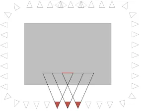
Figure 1 shows the basic acquisition geometry for a hand-held camera. The construction site is circuited and images are acquired the following way: For the creation of the dense point cloud im-ages are taken in an approximated stereo geometry, there should be enough overlap to have every object point in at least three im-ages. Additionally, images have to be acquired looking forward and backward (as shown with dashed lines in the figure) to sup-port the image orientation process, e.g. Structure-from-Motion (SfM). Additional images may be required for supporting the co-registration process, either for the co-co-registration of point clouds from subsequent acquisition dates or of model and point cloud. Images acquired for documentation by other project members can also be used for the reconstruction process.
(Golparvar-Fard et al., 2011) state that images acquired for docu-mentation tasks are sufficient for the as-built reconstruction. The other way round, images made for the purpose of reconstruction may be sufficient for documentation tasks.
b) Equipment
Only a single camera is necessary for acquisition, no further equip-ment is required.
Figure 1. Schematic (as top view) of the acquisition geometry for a hand-held camera. The gray area represents the (active) con-struction area. The red cameras indicate that each reconstructed point should be visible in at least three images.
c) Coverage
The acquisition geometry has to be adopted to the current state of construction. During the construction of the basement elements, images have to be taken around the excavation looking downward. As the building construction increases in height the images are acquired following the schematic in Figure 1 with an appropriate distance to the building’s façade. When a certain height is reached the usage of upright format images (with decreased baseline) or the acquisition of a second row of images might be necessary. The stronger the camera is inclined upwards, the more the conditions for rectification and stereo-matching decline. If the façade is not completely flat, but has for example protruding elements, the occlusions due to lower building parts will increase. Additionally, temporary objects like the scaffold can increase occlusions. Also in this case, the effect becomes larger for upward looking views. Another source of occlusion, which is mainly relevant for the ground floor, are the building site facilities (e.g., construction trailer, site fence), stored material (e.g., prefabricated construction products) or vehicles for delivery purposes (e.g., transit truck mixer). Dependent on the surrounding of the construction site it may be possible to acquire images from elevated positions, e.g., from adjacent buildings, to reduce the invisible areas. Additionally, the platforms in the mast of the crane can be used as acquisition position. In this case the baseline for stereos is limited to the width of the mast (typical value 1m) or the distance between two platforms (typical values are 2.5m, 5mor 10m, dependent on the combination of tower sections) in different heights.
In the worst case, that is a completely covered construction site, this acquisition technique can not be applied.
d) Flexibility
Using a hand-held camera allows to react on the current situation on the construction site by adapting the acquisition positions and order.
e) Automation
The acquisition is a manual process.
f) Disturbance of construction works
As far as the acquisitions are taken from outside the active con-struction area, no disturbance of the concon-struction works exist. If acquisitions within the active area are necessary, it is in the responsibility of the photographer not to interfere any ongoing work.
g) Safety aspects
h) Effort
The duration of acquisition for the images taken around the con-struction site without any disturbances can be estimated (based on the experiment shown in Section 3.1) with 5 min for 25 m façade length. A significant extension of this time results from the use of other (elevated) acquisition positions like the crane.
2.2 UAV
Within this paper UAV acquisition is related to an acquisition with a UAV system having a total weight below 5kgand adherence to the regulation for UAV flights in Germany, which are among others:
• maximal flight height of 100m
• Free line of sight to the UAV in all cases
• No flights over streets
• No flights over crowds
a) Acquisition geometry
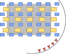
A potential acquisition geometry is shown in Figure 2. The con-struction is acquired in nadir view in two different flight heights, which have to be adopted to the current construction state (mainly the height of the building). The upper flight (e.g., above the cranes) is mainly intended for the stabilization of the orientation process. Additionally, oblique view images are acquired during a flight around the construction site.
Figure 2. Schematic (as top view) of the acquisition geometry for UAV usage. The gray area represents the (active) construction area. The red cameras indicate the oblique view images, the blue and the yellow rectangles the images in nadir view acquired from two different altitudes.
b) Equipment
For UAV acquisition, the aircraft itself, a camera, and a remote control as well as a trained pilot are necessary. The costs for a professional UAV with appropriate configuration are in the range of several 1000e. Additionally, there might be costs for a software for flight planning.
c) Coverage
Generally, all areas, which are not inside the building, are visible for the UAV. But there are also restrictions. A certain security distance has to be kept to the building itself, nearby buildings, and the crane. Inner city construction sites are often surrounded by busy roads, which limits the usage of an UAV or makes it even impossible.
d) Flexibility
There is a high flexibility for the selection of acquisition posi-tions, since in principal every point can be reached, but there are
restrictions because of security reasons or disturbances of the con-struction works (details in the following points f) and g)). The higher the building, the more often the pilot will have to change his position what will lead to more starts and landings. Strong wind or (heavy) rain can make the usage of an UAV impossible. Also the limited flight time may restrict the flexibility. The maximal flight height of 100 m is only a limiting factor for buildings higher than∼70m.
e) Automation
Not regarding any regulations, an autonomous flight of an UAV is feasible, having a predefined flight path and a collision avoid-ance system. There are also works considering the automated calculation of the flight path (Freimuth and König, 2015) using a BIM. A security distance to all objects is defined. Nevertheless the determined flight path can have obstacles. The current state of construction has to be known correctly, to calculate the waypoints only with objects truly existing. Additional objects, which are not modeled in the BIM (e.g., scaffold, crane), are very likely. The flight can be started during a construction break and performed automatically. Until this procedure is operational, a pilot is needed, at least as a backup if something unexpected happens during a pre-planned flight, what can be called semi-autonomous. If a flight path is required which is adapted to the current conditions a completely manual flight can be necessary.
f) Disturbance of construction works
Partly, images can be acquired without disturbance if the UAV has not to enter the active area, that are images from a height higher than the cranes, and images from flights around the site. To cover the whole site, usually also images have to be taken from inside this active area. During this time, there should be no crane movement, what is a strong interference, as far as no time slot can be found where no movements are necessary, e.g., during the lunch break.
g) Safety aspects
The acquisition with UAV shows the largest limitations due to security issues. It has to be ensured that the UAV is no risk for the builders or persons in the surrounding. Especially, a collision with the crane, its hoisting cable or the carried loads has to be avoided. During flight planning, the areas around the crane and the boom have to be omitted, regarding the positioning accuracy of the UAV which is dependent on the accuracy of the navigation unit and the weather conditions (especially the wind strength has to be regarded). The hoisting block should be lifted to its highest point during the flight.
h) Effort
With completed flight planning and automatic flight the acquisition effort is equal to the flight time, eventually with additional time for exchange of the battery. Because of the various difficulties, an accurate flight planning is necessary, which can be sophisticated depending on the complexity of the building site facilities and the surrounding. The flight planning has to be adjusted or renewed with the raising of the building or for changes of the construction site equipment.
2.3 Crane camera
a) Acquisition geometry
construction activity takes place are covered, e.g., for the unload-ing of construction material. These areas can be use to mount control points. To provide a complete coverage and a sufficient overlap for 3D reconstruction, several cameras have to be mounted on the boom (see Figure 5). The basic principle is shown based on a single stereo camera pair in Figure 3 which was the configura-tion in the experiment. Cameras mounted on the boom are always located in the same plane. Because of this reason, the cameras should be calibrated before they are mounted on the crane, since the structure on the ground might also be, at least approximately, a plane.
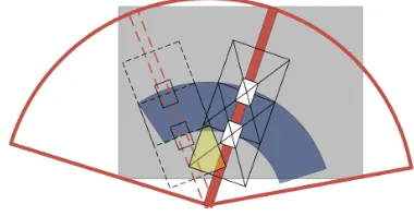
Figure 3. Camera configuration for a crane camera stereo system as used in the experiments on Test Site C. The gray area represents the (active) construction area. The overlap area for the camera pair is shown in blue, the overlap area for the same camera at two different positions is shown in yellow.
b) Equipment
The required components for the crane cameras are described based on the cameras used in the experiments in this paper. The camera is composed of a watertight box which contains a single-board computer for the control of the camera and the intermediate storage of the images, the camera itself, and a mobile communica-tion unit for data transfer. The acquired images are saved on the local storage and subsequently transferred to a server via mobile internet connection. For power supply, a cable is run to the center of the crane. Additionally a network cable is required for data transfer and camera control. For top lewing cranes (with crane cabs) there is power supply on the top of the crane, i.e., there is also a power supply available for the cameras. For (small) bottom lewing cranes there can be the need to provide a power supply for the cameras from the bottom.
(Leung et al., 2008) describe the components for the installation of network cameras for a real-time observation system on a con-struction site system, which would also be suited to be mounted on the boom.
c) Coverage
As stated in a) the crane usually reaches the complete active area. To receive images of the whole construction site the crane has to make a full circle and stop in a certain angle increment for making the acquisition. The steering of the crane and the camera control has to be synchronized for that. Another acquisition procedure (which is used in the experiments here) makes the camera to expose with a certain frequency (e.g., 20 seconds) within a certain time (e.g., 2 hours) and the movements due to the construction activity is used to provide a sufficient coverage. In this case a complete coverage cannot be ensured, but at least it is very likely to cover the complete active area. In this case there might be an overhead of acquisitions which have to be discarded to avoid unnecessary processing time.
For both procedures it has to be regarded that the trolley might be in the view of the camera and occludes the scene.
In the following it is determined how many cameras and which angle increment are necessary to get a complete coverage of the
scene. It is assumed that a camera is mounted at the end of the boom. The incrementαis calculated for a certain overlapqof images at the footprint of the top of the boom (dashed line in Figure 4) with the radiusR, having a certain distanceHto the ground. The increment angle can then be determined for a camera with focal lengthcand sensor heightsyas:
α=asin
(1−q)·sy·H c·R
(1)
In Figure 4 the footprint of the camera at the top is drawn together with the footprint of two additional cameras having an overlap of
p= 0.6along the boom.
Figure 4. Theoretical overlap of three cameras mounted on the boom of a crane. The parameter used for this figure are given in the text below. The required angle incrementαfor a certain overlap at the top of the boom (dashed circle) can be calculated by Equation 1. The amount of overlapping images is given by the numbers.
In the example a camera with a focal lengthc = 3.7 mmand and an image widthsy= 2.9 mmis assumed. In the figure the length of the boomRis 42m. The camera footprints are drawn forH = 21 mwith an overlap ofq= 0.5on the left side and for no overlapq= 0on the right side. The resulting angle increment areα= 11.3◦resulting in 32 stops for the case with overlap and
α= 23◦resulting in 16 stops for the case without overlap. For a height ofH = 5 mabove the current building top the numbers rise to 135 and 67 stops, respectively.
Figure 5. Schematic of a realistic situation for a construction site in side view. The required number of cameras and the corresponding distance between two cameras along the boom are given to get an overlap ofp= 60 %at a certain level.
d) Flexibility
the rigid mounting and the limited accessibility of the cameras on the boom, the camera configuration cannot be adapted easily.
e) Automation
This approach can be designed to be a completely automated process.
f) Disturbance of construction works
If the coverage of the construction site is gained with the move-ment due to the construction activity only, the constructions works are not disturbed in any way. If the procedure with the planned crane movement is used, the crane is not available for the duration of one complete turn with the required stops.
g) Safety aspects
As the cameras and the additional equipment are mounted storm-proof on the crane no safety aspects have to be taken into account.
h) Effort
The effort for acquisition is zero as long everything operates cor-rectly. In comparison to the other acquisition technique this is the only one for which a certain mounting effort has to be consid-ered. Also in case of a malfunction the maintenance of the camera requires more effort because of the difficult access at the boom.
3. EXPERIMENT
3.1 Data
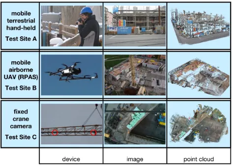
Each acquisition technique is tested on one test site. The test sites are named A to C and are shown in Figure 12.
Test Site A (hand-held) is an inner city construction site with limited surrounding space. Streets and buildings enclose all sides of the site. The images were taken with a hand-held camera, with
c= 24 mmand a sensor size of 36 x 24mm, from the sidewalk of the enclosing streets and from elevated positions on the crane and surrounding buildings (see Figure 6). The as-built state was acquired on six dates with an interval of two to four weeks.
Figure 6. Camera configuration on the test site with hand-held acquisition. Here, additional images are taken from the crane tower (in the back) and a roof deck of an adjacent building (on the left). A course model of the complete building is shown in gray.
Test Site B (UAV) is a peripheral construction site with neighbor-ing houses at one side and grassland on the other. The acquisition
was performed with an UAV carrying a camera withc= 18 mm and a sensor size of 23.5 x 15.6mm. The as-built state was ac-quired (approximately) monthly on five dates. The camera posi-tions for one of these dates is shown in Figure 7. For this, three flights with a duration of 10 to 15minwere needed.
Figure 7. Camera configuration on the test site with UAV ac-quisition. A course model of the complete building is shown in gray.
Test Site C (Crane) is an inner city construction site. Two cameras are mounted on the boom of the crane with a distance ofB = 8 m. The configuration corresponds to the sketch in Figure 3. A camera configuration from one of the acquisitions is shown in Figure 8. The cameras (c= 3.6 mm, sensor size: 3.9 x 2.9mm) were mounted during the erection of the crane. The boom was completely mounted and lying on the ground of the excavation during the time of the erection of the tower. In this time the boom was easily accessible and the cameras were mounted and the power and network cables were run to the center.
Figure 8. Camera configuration on the test site with a crane camera stereo configuration. A course model of the complete building is shown in gray.
3.2 Results
using the crane cameras (C) as for the other two test sites (A and B). The reason is that no ground truth is available for Test Site C and only a first study using a single stereo pair was conducted.
a) Results for Test Site A and B
The first evaluation is based on the visible areas. For that the ground truth is used. From the ground truth, these building el-ements are selected which were newly erected with respect to the previous acquisition date. That means that five acquisition dates are evaluated for Test Site A and four for Test Site B. Each plane of the selected building elements is classified as unknown (i.e., invisible), visible (i.e., reconstructed points are existing) or conflict (conflicting information), based on visibility constraints described in (Tuttas et al., 2015). From the visible planes it is addi-tionally calculated how much of their area is covered with points, since a lot of planes are not completely visible. For determining the covered area the element planes are split into raster cells of size 5 x 5cm. At last, for each raster cell it is checked whether reconstructed points are existing.
Test Site A
aream2 % of TA % of V total area (TA) 7415
unknown 6475 87 %
visible (V) 927 12 %
covered 388 5 % 42 %
conflict 14 1 %
Table 2. Visible area on Test Site A for building elements which have been newly erected between two acquisition dates, sum for five acquisition dates.
Test Site B
aream2 % of TA % of V total area (TA) 12112
unknown 6883 57 %
visible (V) 4642 38 %
covered 2173 18 % 47 %
conflict 588 5 %
Table 3. Visible area on Test Site B for building elements which have been newly erected between two acquisition dates, sum for four acquisition dates.
As can be seen from Table 2 and 3 the area of visible elements is 12 % of the total area (ranging from 2 % to 39 % for single acquisition dates) on Test Site A and 38 % (ranging from 17 % to 46 % for single acquisition dates) on Test Site B.
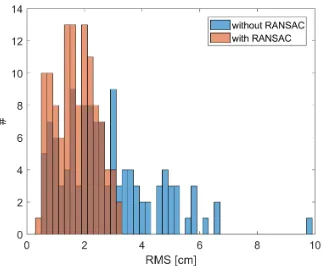
For the evaluation of the reconstruction accuracy received with the configurations used in these test data, points are extracted in a bounding box around the planes, marked as newly built in the ground truth. For each of the planes a plane fit is performed, once on all extracted points and once using RANSAC (using 6cm distance as threshold for inliers). Only planes are selected which are larger than 1m2and for which at least 20 percent of the area is covered with points. For Test Site A this are 118 and for Test Site B 139 planes.
Figure 9 and Figure 10 show the histograms for the RMS for all plane fits. The mean RMS for the Test Site A is 2.7cmwithout RANSAC and 1.6cmusing RANSAC, for Test Site B the mean RMS are 3.3cmand 1.9cm, respectively.
Figure 9. Histogram of the RMS of the fitted planes on Test Site A
Figure 10. Histogram of the RMS of the fitted planes on Test Site B
b) Results for Test Site C
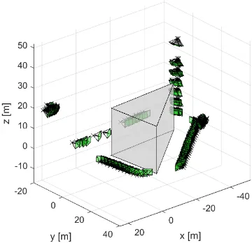
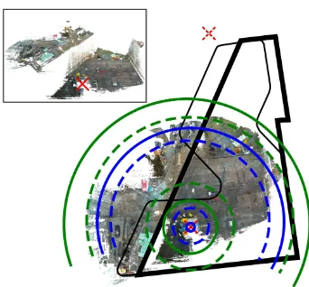
Figure 11 shows a top view of a point cloud reconstructed from the ground of the excavation. At this moment the cameras are mounted 36mabove the ground. The total height of the building is 29m, meaning that the smallest distance between camera and a building element is 7m. In the figure the footprints of the cameras for a height of 30mand 20m(dashed) are shown. With this configuration, the width of the overlapping part is 24.4mand the approximated Z accuracy is 4.7cmforH = 30 mand 13.4 m and 2.1cmforH= 20 m, respectively.
The approximated accuracy is estimated with the following equa-tion, assuming thatσd= 1pixel:
σZ≈ H
2
c·B ·σd (2)
As can be seen in Figure 8 the camera positions are not distributed evenly, since images were acquired in a time interval of 20swithin 2 hours. The reconstruction quality of course is then dependent on the actual camera positions, leading to RMS errors for selected plane fits (inH= 27 m) fromcmtodmlevel.
In the scenario shown here there is no overlap between the images of the stereo camera if the distance to the building reaches 7.4m and 50 % overlap if it reaches 14.8m.
4. DISCUSSION AND OUTLOOK
Figure 11. Point cloud of the excavation and footprint of the cameras with 30mand 20m(dashed) distance to the ground. The blue lines indicate the inner camera, the green lines indicate the outer camera. The position of the crane is marked by a red cross. The position of a second crane (without camera) is marked by a red cross with dashed lines. The layout of the building is the thin black line, the layout of the excavation is the bold black line. On the upper left the point cloud is shown in a side view.
The capabilities of the different techniques are evaluated based on visibility and accuracy. The visibility of newly erected build-ing elements is assessed based on the camera configurations used for the experiments. The results show that the amount of visible elements is low, reaching better values for the UAV acquisition compared to the hand-held acquisition. There are various reasons for that. The larger the time between two acquisition dates the more building elements are surrounded by other newly built ob-jects and are not visible for acquisitions from outside the building. To reduce this either the acquisition frequency has to be increased or the monitoring has to be extended with indoor data acquisition. Another reason is that there are limitation on reachable acquisition positions which prevent the reconstruction of the whole building. For example in the case of the test site with the hand held camera, the gaps between the camera positions in Figure 6 are related to construction site trailers and busy crossroads, which can not be entered easily. Obviously the visibility of slabs is limited for the hand-held case with no elevated acquisitions, while the visibility of pillars (at least the vertical parts) is limited in the nadir view of the crane camera.
The accuracy of the reconstructed points varies depending on the acquisition geometry which could be established, meaning that not all elements can be acquired from a distance with an appropriate baseline or with a sufficient number of images. The accuracy evaluation is based on the reconstructed planes of Test Sites A and B showing an mean RMS error of approximately 2cmranging from 1 to 3cm.
The higher the required acquisition frequency, the more important is a small effort for a single acquisition and a high automation, what prefers the usage of crane cameras. For the crane scenario, basic considerations on the necessary camera configuration are given, and a first experiment is conducted using a single camera pair. Since an acquisition plan without synchronization to the crane movement was used on this test site, the results for the reconstruction accuracy are varying due to the available images and the changing base to height ratio during the rise of the build-ing. The RMS of fitted planes can be in the range of the other techniques, but reaches clearly higher values up todmlevel. The missing overlap as well as the different baselines required to reach a sufficient accuracy for different building heights show the need
for a camera configuration as shown in Figure 5.
The creation of a complete point cloud of the construction may require the combination of the different acquisition techniques. Hand-held images can extend the coverage of UAV acquisition especially for lower building parts, if there are too many objects on the ground to receive images in horizontal view with the UAV, or if there are objects that prevent the UAV of approaching some required acquisition positions. Also crane cameras and hand-held acquisition can be complementary. The inner area and slabs can be better acquired from above, while the elements facing towards the surrounding can be better acquired from outside the construction area with a hand-held camera.
The photogrammetric point clouds are used for progress monitor-ing or the detection of temporary objects. For Test Site A results are shown in (Tuttas et al., 2015, Braun et al., 2015a, Braun et al., 2015b, Tuttas et al., 2014a) for progress monitoring (built as-planned comparison). Scaffold elements are detected in (Xu et al., 2015), also for Test Site A. In future work the as-built as-planned comparison will also be evaluated for the other test sites.
ACKNOWLEDGEMENTS
This work is supported by the German Research Foundation (DFG) under grants STI 545/6-1 and BO 3575/4-1.
We like to thank Leitner GmbH & Co Bauunternehmung KG and Kuehn Malvezzi Architects (Test Site A), Baureferat H5, Landeshauptstadt M¨nchen, Baugesellschaft Mickan mbH & Co KG, h4a Architekten, Wenzel + Wenzel and Stadtvermessungsamt München (Test Site B) as well as Staatliches Bauamt München, Baugesellschaft Brunner + Co and BKL (Baukran Logistik GmbH) (Test Site C) for their support during the case studies.
We also like to thank Konrad Eder for the support during data acquisition and the Institute for Materials Handling, Material Flow, Logistics at TUM for providing the crane cameras.
REFERENCES
Bosché, F., 2010. Automated recognition of 3D CAD model objects in laser scans and calculation of as-built dimensions for dimensional compliance control in construction.Advanced Engi-neering Informatics24(1), pp. 107–118.
Braun, A., Borrmann, A., Tuttas, S. and Stilla, U., 2015a. A con-cept for automated construction progress monitoring using BIM-based geometric constraints and photogrammetric point clouds.
Journal of Information Technology in Construction20, pp. 68 – 79.
Braun, A., Tuttas, S., Borrmann, A. and Stilla, U., 2015b. Au-tomated progress monitoring based on photogrammetric point clouds and precedence relationship graphs. In: The 32nd Interna-tional Symposium on Automation and Robotics in Construction and Mining (ISARC 2015).
Freimuth, H. and König, M., 2015. Generation of waypoints for UAV-assisted progress monitoring and acceptance of construction work. In: CONVR2015.
Golparvar-Fard, M., Peña Mora, F. and Savarese, S., 2011. Mon-itoring changes of 3D building elements from unordered photo collections. In: Computer Vision Workshops (ICCV Workshops), 2011 IEEE International Conference on, pp. 249–256.
Figure 12. Acquisition devices, example images and resulting point clouds for construction site monitoring
Ham, Y., Han, K., Lin, J. and Golparvar-Fard, M., 2016. Visual monitoring of civil infrastructure systems via camera-equipped unmanned aerial vehicles (UAVs): a review of related works.
Visualization in Engineering.
Ibrahim, Y. M., Lukins, T. C., Zhang, X., Trucco, E. and Kaka, A. P., 2009. Towards automated progress assessment of workpack-age components in construction projects using computer vision.
Advanced Engineering Informatics23(1), pp. 93–103.
Irizarry, J. and Costa, D. B., 2016. Exploratory study of potential applications of unmanned aerial systems for construction manage-ment tasks.Journal of Management in Engineering.
Karsch, K., Golparvar-Fard, M. and Forsyth, D., 2014. Con-structAide: analyzing and visualizing construction sites through photographs and building models.ACM Trans. Graph.
Kim, C., Kim, B. and Kim, H., 2013a. 4D cad model updating using image processing-based construction progress monitoring.
Automation in Construction35, pp. 44–52.
Kim, C., Son, H. and Kim, C., 2013b. Automated construction progress measurement using a 4D building information model and 3D data.Automation in Construction31, pp. 75–82.
Kluckner, S., Birchbauer, J.-A., Windisch, C., Hoppe, C., Irschara, A., Wendel, A., Zollmann, S., Reitmayr, G. and Bischof, H., 2011. AVSS 2011 demo session: Construction site monitoring from highly-overlapping MAV images. In: Advanced Video and Signal-Based Surveillance (AVSS), 2011 8th IEEE International Conference on, pp. 531–532.
Leung, S.-w., Mak, S. and Lee, B. L. P., 2008. Using a real-time integrated communication system to monitor the progress and quality of construction works.Automation in Construction17(6), pp. 749–757.
Lukins, T. C. and Trucco, E., 2007. Towards automated visual assessment of progress in construction projects. In: BMVC.
Maalek, R., Lichti, D. D. and Ruwanpura, J., 2015. Robust classifi-cation and segmentation of planar and linear features for construc-tion site progress monitoring and structural dimension compliance control.ISPRS Ann. Photogramm. Remote Sens. Spatial Inf. Sci.
II-3/W5, pp. 129–136.
Rothermel, M., Wenzel, K., Fritsch, D. and Haala, N., 2012. SURE: Photogrammetric surface reconstruction from imagery. In: LC3D Workshop.
Turkan, Y., Bosché, F., Haas, C. T. and Haas, R., 2012. Automated progress tracking using 4D schedule and 3D sensing technologies.
Automation in Construction22, pp. 414–421.
Tuttas, S., Braun, A., Borrmann, A. and Stilla, U., 2014a. Compar-ison of photogrammetric point clouds with BIM building elements for construction progress monitoring. Int. Arch. Photogramm. Remote Sens. Spatial Inf. Sci.XL-3, pp. 341–345.
Tuttas, S., Braun, A., Borrmann, A. and Stilla, U., 2014b. Konzept zur automatischen Baufortschrittskontrolle durch Integration eines Building Information Models und photogrammetrisch erzeugten Punktwolken. In: E. Seyfert, E. Gülch, C. Heipke, J. Schiewe and M. Sester (eds), Gemeinsame Tagung 2014 der DGfK, der DGPF, der GfGI und des GiN, pp. 363–372.
Tuttas, S., Braun, A., Borrmann, A. and Stilla, U., 2015. Vali-dation of BIM components by photogrammetric point clouds for construction site monitoring.ISPRS Ann. Photogramm. Remote Sens. Spatial Inf. Sci.II-3/W4, pp. 231–237.