LATENCY DETERMINATION AND COMPENSATION IN
REAL-TIME GNSS/INS INTEGRATED NAVIGATION SYSTEMS
P. D. Solomon a/b, J. Wang b, C. Rizos b
a Clearbox Systems, Lane Cove, NSW 2066, Australia - pauls@clearboxsystems.com.au
b
School of Surveying and Spatial Information Systems, University of New South Wales, Kensington, Australia – {jinling.wang, c.rizos}@unsw.edu.au
Commission I, WG I/V
KEY WORDS: UAVs, Latency, Real-time, EKF, Delayed Measurements
ABSTRACT:
Unmanned Aerial Vehicle (UAV) technology is now commonplace in many defence and civilian environments. However, the high cost of owning and operating a sophisticated UAV has slowed their adoption in many commercial markets. Universities and research groups are actively experimenting with UAVs to further develop the technology, particularly for automated flying operations.
The two main UAV platforms used are fixed-wing and helicopter. Helicopter-based UAVs offer many attractive features over fixed-wing UAVs, including vertical take-off, the ability to loiter, and highly dynamic flight. However the control and navigation of helicopters are significantly more demanding than those of fixed-wing UAVs and as such require a high bandwidth real-time Position, Velocity, Attitude (PVA) navigation system.
In practical Real-Time Navigation Systems (RTNS) there are delays in the processing of the GNSS data prior to the fusion of the GNSS data with the INS measurements. This latency must be compensated for otherwise it degrades the solution of the navigation filter. This paper investigates the effect of latency in the arrival time of the GNSS data in a RTNS. Several test drives and flights were conducted with a low-cost RTNS, and compared with a high quality GNSS/INS solution. A technique for the real-time, automated and accurate estimation of the GNSS latency in low-cost systems was developed and tested. The latency estimates were then verified through cross-correlation with the time-stamped measurements from the reference system. A delayed measurement Extended Kalman Filter was then used to allow for the real-time fusing of the delayed measurements, and then a final system developed for on-the-fly measurement and compensation of GNSS latency in a RTNS.
1. INTRODUCTION
In real-time implementations of GNSS/INS loosely-coupled systems the GNSS measurements suffer from a delay such that the measurements must be fused late with respect to the state of the system. This is because the inertial loop in a navigation filter typically runs at a much higher rate than the rate at which GNSS measurements come in and several inertial epochs will have passed before a GNSS measurement is ready for fusion.
There are several methods for fusing these delayed measurements in an Extended Kalman Filter (EKF), however the delay or latency must be known ahead of time in order to apply them. Without accurate estimation of this parameter, real-time loosely-coupled GNSS/INS systems will perform sub-optimally and degrade under high dynamic conditions. This paper focuses on developing a reliable method for estimating GNSS latency in loosely-coupled GNSS/INS systems.
The structure of this paper is as follows, Section 2 describes the motivation for this work and why this is often overlooked. Section 3 builds a case for why GNSS latency is to be reasonably expected. Section 4 explains the experimental setup and the tests that were performed, which leads into Section 5and 6 which is where the method of GNSS latency estimation is described and
verified against an external reference system. To round out the discussion Section 7 describes methods for dealing with delayed GNSS measurements once the delay is accurately known and concluding remarks are made in Section 8.
2. MOTIVATION & BACKGROUND
This work is part of the development towards a low-cost light weight flight control system for small (<100kg) helicopter UAVs at Clearbox Systems. Compared to fixed-wing aircraft, helicopters are naturally unstable vehicles and require constant high bandwidth (100Hz+) control inputs to hover. The challenge is similar to balancing a broom upside-down on one’s hand; even when it is perfectly upright it always has a tendency to start falling in a random direction. In order to actively control a helicopter UAV, its Position, Velocity and Attitude (PVA) must be reliably and accurately known at all times.
and an EKF was used as the fusion filter based on the PSI-angle error model (Groves, 2008).
Throughout the development of the real-time navigation system (RTNS) the lack of synchronisation between the GPS and INS caused a more significant problem than expected. The issue arises because a GPS single point solution cannot be processed instantaneously. Thus when a GPS measurement update is received it describes a past location of the platform. If this old measurement is then fused with the current platform state then it will degrade the overall system performance.
It is noted that research conducted prior to the development of the real-time GPS/INS navigation systems tend to overlook the issue of delayed measurements. This may be attributable to the fact that some RTNSs that are experiencing relatively low speed dynamics would have minimal errors due to the latency, and the filter would still correctly converge. In these cases the errors due to latency may go unnoticed or be incorrectly attributed to sensor noise.
In other studies, the inertial data is captured and the time of the recorded time-stamp. This is because the GPS time-stamp is an artificial measurement of when the transmission left the satellite, not when the data was presented in these studies cannot be directly implemented in real-time systems without further consideration.
3. LATENCY IN GNSS MEASUREMENTS
There are a number of sources of delay that can be reasonably expected in a GNSS receiver. These can be grouped into three main categories: measurement, processing, and data transmission. A GNSS receiver works by accurately measuring the time of reception of multiple CDMA spread signals. The receiver has a series of correlator channels which track both the frequency and code phase using internal Phase Locked Loops (PLLs) measurement delay will contribute less than 10ms to the overall GNSS system delay.
In the processing step, the GNSS receiver will need to: (i) estimate the Time of Transmission (ToT) for each signal received, taking into account relativistic, ionospheric, and tropospheric effects; (ii) calculate the
position of each of the GNSS satellites at the ToT, and then (iii) solve for receiver clock offset and position using a Least Squares estimator. This process is then repeated a number of times to converge on the best estimate of position and receiver clock offset. Depending on the computation power available to the GNSS receiver it is estimated that this processing step could contribute anywhere from 100ms – 1s to the overall delay. This is based on the maximum update rate of modern receivers and rates from 1Hz to 10Hz are currently commonplace.
Finally, once the GNSS receiver has estimated its position it needs to convey this information to the computer that will be responsible for running the EKF. In most traditional receivers the data is transmitted via a NMEA message over serial, with transmission rates ranging from 2400 baud to 19200 baud. A typical NMEA position message, such as the GGA message, is 70 characters long. The worst case transmission delay assuming 2400 baud, 1 start bit, 8 data bits, Even Parity, and 2 stop bits comes to 350ms. Modern receivers can minimise this delay by using high speed transmission methods such as USB.
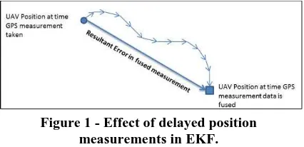
In a worst case scenario, data could be arriving to the EKF to be fused up to a total of 1360ms late. If this was occurring on a UAV that is travelling at 200kph, then the vehicle will have moved on by 75.5m by the time the
Figure 1 - Effect of delayed position measurements in EKF.
4. DESCRIPTION OF THE EXPERIMENT
For this study several large (1-2 hour data) sets were collected for analysis. These data sets were collected by fitting a vehicle with measurement systems each containing GPS receivers and Inertial Measurement Units (IMUs). The GPS receivers both used a common antenna and the IMUs were mounted on top of each other to ensure that the same data was collected on each system. One of the systems was a high quality reference system that was used as a truth reference for the experiments, and the other system was the real-time system under test. These systems were mounted on the roof of a car as shown in Figure 2 and then driven around an open air car park that provided minimal signal blockage to the GPS system. The route consisted of laps of the car park, stops
and starts, “figure eights” and some high-speed sections to ensure that the navigation system was exposed to a wide range of dynamics.
The data from both the GPS and the IMU were logged onto a laptop and the IMU data was time-stamped with GPS time using external GPS time-stamping hardware. The time-stamping hardware used both GPS TOW and a 1 Pulse Per Second (1PPS) signal to synchronise a FPGA which is responsible for time-stamping all inertial measurements as they came through the device.
Figure 2 - Navigation system mounted on roof of car.
The real-time GPS/INS navigation system that is investigated in this paper was developed by the first author for helicopter UAV experimentation. It consists of a u-blox LEA-5T single-frequency GPS receiver, which provides both a computed position and a raw mode output which includes pseudo-range, Doppler shift and carrier phase measurements at up to 2Hz (LEA-5T Precision Timing Module, 2011). The IMU chosen was a Silicon Sensing Systems DMU02 which was selected primarily because of the vibrating bell type gyroscope structure which exhibits good vibration rejection performance, its low-cost, and size (Dynamics Measurement Unit DMU02, 2011). The integration is performed on a Clearbox Systems n2 flight computer that has been modified to allow direct connection of the IMU. The sensors are integrated in a loosely-coupled EKF that uses the psi-error model. The update rate of the filter is 100Hz, and the GPS measurements are fused at 500ms intervals.
5. ESTIMATION OF LATENCY
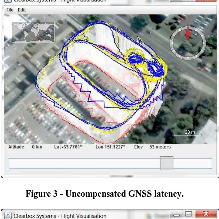
To produce an initial estimate of the GPS latency in the RTNS the data was post processed with varying levels of delay and analysed. This was achieved through the development of an EKF visualisation tool which allows users to quickly process GPS/INS data sets with various time offsets in the GPS data and to visualise the results. Through this technique it was quickly established that an improvement could be found in the resultant fused data by compensating for the GPS delay. The visualisation from this software is shown in Figure 3 & 4 with the integrated vehicle track depicted as a blue track in a 3D environment, and the original GPS track in yellow for reference.
Using this software, rapid changes can be made to the latency estimate and the track recomputed in faster than real-time so users can get a good sense of the relationship
between latency and integrated ground track error. The two figures compare the visualisation of data that has an uncompensated latency of 1.2 second with data that has had the latency correctly compensated. The effects of GPS latency can be seen particularly well in the “figure
eight” section of the test drive. When the GPS data is
uncompensated, the EKF appears to be converging, however as soon as the vehicle starts to undergo high dynamic movement the resultant track shows significant error. This is in stark contrast to the correctly
compensated data in which the “figure eights” are both
open and round.
This approach confirmed that GPS latency was having a detrimental effect on filter performance and stability. However this is a subjective measure of the latency and it is not possible to get an accurate and repeatable estimate of the latency. Hence a method was developed to mathematically estimate latency. The development of this method starts with the identification of a suitable error metric of filter performance.
Figure 3 - Uncompensated GNSS latency.
Figure 4 - Compensated GNSS latency.
fused measurements refer to a previous position rather than the current position of the filter at time of fusion. The error will first be seen in the innovation of the Kalman filter being larger than it should be. By averaging the square of the innovation samples across a given filter run, a metric is produced that can be used to compare latency estimates. This metric will have a minimum bound which can be attributed to the measurement noise, however by minimising this metric the GPS latency can be estimated.
The innovation error metric is defined as follows:
∑ 1
̂ 2
Where is the innovation, is the last measurement and ̂ is the expected value of the measurement due to the current filter state.
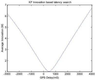
To test the efficacy of this approach, the experimental data was post-processed with GNSS latency offsets from -3 seconds through to +4 seconds in 10ms increments and plotted as the average innovation across the data set. The resultant plots shown in Figures 5 and 6 show a clear relationship between the GPS delay and the average innovation in the EKF. The slopes on the resulting graphs are clearly sloping downwards with a well defined minimum at the GPS delay. This shape allows for the determination of the minimum and the best estimate of the GPS latency. In the real-time GPS/INS system under test, this latency was found to be 460ms.
Figure 5 - KF innovation based latency search.
Given the smooth nature of the innovation average response with a clear minimum, it is possible to develop a Kalman filter design that can measure and compensate for this delay in real-time. The approach for online measurement is to run three delayed measurement Kalman filters in parallel, a lead, lag and prompt filter (which is somewhat similar to the common approach used in GPS correlator design). The delayed measurement Kalman filter is capable of effectively compensating for late measurements if the measurement
delay is known. In the prompt filter, the measurement delay is set to the current best estimate of measurement delay known to the system. The lead filter is set to 10mS ahead of this and the lag filter is set to 10ms behind.
Figure 6 - Zoom of latency search.
A moving average of the innovation is taken for each filter and by comparison of these moving averages it can be determined if the filter is currently leading, lagging or correctly estimating the GPS delay. The GPS delay is then updated by 10ms steps each epoch. This method is only valid when the system under measurement is in motion and the velocity of the vehicle is estimated with the filter. While the velocity is below some threshold this update method is disabled. This is because the vehicle needs to move more than the GPS variance per update period to ensure the delay is observable independently of receiver noise. The ideal value for this threshold depends on the update rate of the GPS receiver and the noise in the GPS measurements.
6. VERIFICATION OF LATENCY ESTIMATE
To confirm that the estimate for GPS latency is valid, a second technique was used to compute the latency of the GPS data received by the RTNS. The reference system that was used in the experiment has the capability to accurately time-stamp all of the inertial measurements with GPS time. This is done on a custom FPGA-based synchronisation board that is fed with a GPS derived 1PPS reference signal.
All of the inertial measurements were also time-stamped however these were time-stamped with the “wall clock” of the RTNS. By lining up the inertial data from the two systems it is possible to determine the offset between the
“wall clock” of the RTNS and the actual GPS time. This was achieved by peaking a cross-correlation between the two inertial data sets whist altering the time offset between the two data sets. Once the wall-clock time on the RTNS is known with respect to GPS time the GPS latency can be directly measured as the GPS packets contain the reference time of each measurement. This technique was originally developed to test the accuracy of a hardware GPS/INS syncronisation device (Ding, 2008).
-30001 -2000 -1000 0 1000 2000 3000 4000
2
380 400 420 440 460 480 500 520
By using this technique, the GPS latency was found to be 430ms which is close to the previously estimated 4s0ms. The 30ms error is believed to be related to a clock drift error in the RTNS and is currently being investigated.
7. METHODS FOR REAL-TIME EKF
PROCESSING OF DELAYED MEASUREMENTS
If it is known that measurements are significantly delayed then there are standard techniques for fusing these late measurements in an EKF. The real-time methods can be broken down into two categories, measurement extrapolation (Larsen et al, 1998), and filter replay (Simon, 2006). In the first approach the delayed measurement is made current by applying a series of transformations to it. These transformations match the transformations the state estimate has undergone between the measurement time and the current time. Once the measurement is transformed to the current time it can be fused as normal.
In the second approach the filter is rewound to the point in time that the measurement was taken and then the measurement is applied. The filter is then replayed forward in time using the reverse update steps. This is typically implemented by keeping a lagged copy of the filter to fuse the measurements with, then after each measurement fusion the lagged filter is replayed forward to replace the current estimate.
8. CONCLUSION
In this paper a technique was described for the on-line estimation of the GNSS delay in a real-time GNSS/INS EKF based navigation system. The method was used to estimate delay in a real-time system and the results were verified using a reference system. It was shown through visualisation and tests that a correctly delayed compensated filter produces a more accurate and stable EKF solution and minimises convergence issues. As this is an initial study on GNSS delay it is expected that there will be more efficient methods for estimating delay developed in follow on work. Another approach worth consideration is tracking the GNSS latency error as part of the error state in the EKF.
9. REFERENCES
Ding, W., Wang, J., Li, Y., Mumford, P., & Rizos, C. (2008). Time Syncronization Error and Calibration in Integrated GPS/INS Systems. ETRI Journal, Volume 30, Number 1, 59-67. Dynamics Measurement Unit DMU02. (2011, March 28).
Retrieved March 28, 2011, from Silicon
Sensing Systems:
http://www.sssj.co.jp/en/products/dmu/dmu02/i ndex.html
Groves, P. D. (2008). Principles of GNSS, Inertial, and Multisensor Integrated Navigation Systems. Artech House.
Larsen, T. D., Andersen, N. A., Ravn, O., & Poulsen, N. K. (1998). Incorporation of Time Delayed Measurements in a Discrete-time Kalman Filter. Proceedings of the 37th IEEE Conference on Decision & Control (pp. 3972-3977). Tampa, FL, USA: IEEE.
LEA-5T Precision Timing Module. (2011). Accessed March 28, 2011, from uBlox: http://www.u-blox.com/en/lea-5t.html