Comparison of Two Fuzzy Logic Controller Schemes
for Position Control of AR.Drone
Veronica Indrawati, Agung Prayitno, Gabriel Utomo
Dept.of Electrical EngineeringUniversity of Surabaya, UBAYA Surabaya, Indonesia
[email protected], [email protected], [email protected]
Abstract — This paper explains the AR.Drone position control scheme using Fuzzy Logic Controller (FLC) in a 3 dimensional coordinate. This control scheme uses two FLC block, for X-Y position and Z position. The inputs of FLC block for X-Y position are distance and angle, while the output is pitch and yaw rate. Z-position will be controlled by another FLC block, which has two inputs, namely setpoint of z and real position of z, while the output is vertical rate. To compensate the sideward speed of the drone, roll compensation is used. The implementation results show that the AR.Drone can achieve the desired position with settling time for x, y position approximately 6 seconds, while z position around 10 seconds. Response x has the oscillation of approximately 5% around the set point. The implementation result are also compared with other fuzzy control for the same setpoint position
Keywords—AR.Drone position control; fuzzy logic control;roll compensation; pitch compensation
I. INTRODUCTION
AR.Drone is one of Parrot’s quadrotors which is widely used as a research platform in some universities in the world nowadays. AR.Drone is preferred because it is reasonably priced and has additional sensors, as well as included onboard controller and internal software. At first, AR.Drone was made as a toy which can be played using applications that can be downloaded from Google Play for Android devices or AppStore for iOS devices, namely AR.FreeFlight 2.0 and AR.Race 2. The launching of Software Development Kit (SDK) enables users to access the internal controller of AR.Drone through Wi-Fi communication, so they can maneuver said AR.Drone using various control algorithm made beforehand.
AR.Drone is constructed of the x-form frame, which is made of carbon fiber pipe tip. Of which ends’ are brushless motors complete with propellers. In its middle frame the main body is made of plastic fiber in which there is onboard electronics, 2 cameras (front and bottom) and Lithium-Polymer (Li-Po) battery. In the onboard electronics there are 2 board, namely motherboard and navigation board. On the
motherboard are the processor, Wi-Fi chips, front and bottom camera. While navigation board is equipped with a microcontroller board that act as interface to the sensor. The sensors used are accelerometer, gyroscope and ultrasonic altimeter [1].
In this research, the type of the AR.Drone used is type AR.Drone 2.0 Elite Edition, Fig.1 [1]. The AR.Drone has 4 inrunner brushless motors 14.5W 28,500 RPM. The motherboard equipped with 32-bit ARM Cortex A8 1GHz processor with 800MHz DSP TMS320DMC64x video, 1GB DDR2 RAM at 200MHz, 60 FPS QVGA vertical ground speed cameras for measurement, USB 2.0 high speed for extensions, Wi-Fi chips, HD Camera 720p 30 fps. While navigation board has 3-axis gyroscopes 2000°/second precision, three axis accelerometers +/- 50 mg precision, three-axis magnetometers 6° precision , Pressure +/- 10 Pa precision sensors, ultrasound sensors for measurement of ground altitude. And the internal software used is Linux 2.6.32 [2].
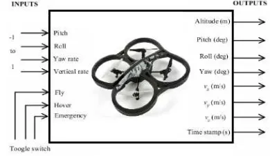
With the Wi-Fi communication, the user is able to access drone internal controller drone from a computer in a ground station. The user can maneuver the AR.Drone’s flight by providing a range of value -1 to 1 on pitch, roll, yaw rate and vertical rate. Pitch is used to move backward (+) and forward (-), roll used to move to the right (+) and left (-), yaw rate used for the movement pivot clockwise (+) and pivot counterclockwise (-) while vertical rate to up (+)and down (-).
Fig. 1. AR.Drone Inputs – Outputs
2015 7th International Conference on Information Technology and Electrical Engineering (ICITEE), Chiang Mai, Thailand