Fouling and Rejection Behaviour of Ultrafiltration for Oil
in Water Emulsion Separation
Nita Aryantia, Agus Hadiyarto, Wiharyanto Oktiawanb
a
Chemical Engineering Department, Faculty of Engineering, Diponegoro University, Jl. Prof Sudharto,SH-Tembalang, Semarang INDONESIA
b
Environmental Engineering, Faculty of Engineering, Diponegoro University Jl. Prof Sudharto, SH-Tembalang, Semarang INDONESIA
E-mail: [email protected]
Abstract :
Oily waste water has been generated from food, automotive, metal processing industries as well as petroleum exploration and refinery. Polyethersulfone ultrafiltration membrane was investigated for treatment of oil in water emulsion. The emulsion models were made based on industrial oily wastewater characteristic in the oil refinery. Flux and rejection were evaluated in order study the fouling and rejection behaviour. Results showed that more than 90% of COD and 85% surfactant were rejected. The permeate flux decline was analyzed in order to study the membrane fouling. In addition, the Hermia model is adopted to investigate the fouling mechanism during ultrafiltration of oil in water emulsion. A alyze of lo ki g e ha is usi g Her ia’s odel re eal that ultrafiltratio of oth diesel a d i eral oil ha e good agreement with complete blocking mechanism.
Keywords:e ulsio , fouli g, Her ia’s odel, oily wastewater, ultrafiltration
1. Introduction
Oily wastewater is one of industrial wastewater source in food, automotive, metal processing as well as petroleum exploration and refineries. Exploration of crude oil consumes water injection and results on produced water. Exploration of 1 barrel crude oil requires 3 barrel produced water [1]. In addition, petroleum refineries result on oily wastewater 0,4 to 1,6 times of oil production [2]. Typical composition ranges of produced water generated from onshore oil and gas operation include 50-1000 mg/L of total oil and grease. Indonesian environmental regulations stated that maximum total oil and grease concentrations in discharge waters be 25–50 mg/L .
The oily wastewaters were found in the form of free-floating oil or oil in water emulsion. Free-floati g oil or unstable oil/water emulsions can be readily removed by using conventional separation processes [3, 4]. However, for removing stable oil/water emulsion wastewater requires complex process comprising demulsification (breaking) of emulsion using coagulants, acids or heat treatment followed by separation of oil from water. The methods of oily wastewater treatment are frequently not efficient enough especially when the oil droplets are finely dispersed and the concentration is very low.
The membrane techniques such as ultrafiltration (UF) is a promising methods for emulsion separation.
Ultrafiltratio is a lo -pressure e ra e filtratio pro ess hi h operates between a pressure of 5 to 150 psi, an order of magnitude lower than that of reverse osmosis [5]. The pore sizes in UF membranes range from 0.001 m to 0.1 m, which result in rejections of compounds in the molecular weight range from 1000 to 100 000 Daltons. Generally the compounds that make up the petroleum hydrocarbon (PHC) contamination commonly detected in surface waters are semivolatile compounds such as benzene, ethylbenzene, toluene, xylene (BETX) which have molecular weights lower than the molecular-weight cut off MWCO ra ge of the ultrafiltratio e ra es [6]. However, limitation in ultrafiltration of oily wastewater is membrane fouling. The main mechanisms of fouling involved surface area, pore clogging and pore restriction due to adsorption onto the pore walls [7].
The Her ia’s odel des ri es e ha is of e ra e fouli g ased o lo ki g filtratio la , o sisti g of
Figure 1. Blocking Mechanism by Hermia Model [7]
In the complete blocking model, it is assumed that every solute participate in blocking the entrance of the membrane pores completely. For intermediate blocking, it is assumed that each solute is settled on previously deposited solute. Standard blocking considers the deposition of each solute to the internal pore wall. The cake layer formation applied based on the accumulation of the sollute on the membrane surface in the cake form.
This paper reports data for the ultrafiltration of oil in water emulsion using diesel oil and mineral oil as dispersed (oil) phase. The performance in the term of COD and surfactant rejection as well as fouling mechanism
ased o Her ia’s odel ere deter i ed.
2. Materials and Methods
Feed of oil in water emulsion models were prepared by dispersing oil phase (diesel oil and mineral oil) into continuous phase using Manual Ultra Turax Homogenizer, 2500 rpm for 5 minutes. The diesel oil were provided by Pertamina and the mineral oil was a commercial cutting oil, Eontrim E 9010, having specifiication of 70% v mineral oil, 30% v surfactant, co surfactant and corrosion inhibitor. All oils were used without further treatment. The concentration of oil was 50 mg/L continuous phase. The continuous phase was a mixture of 2% v/v Tween 80 (Polysorbate 80) and distilled water.
The ol in water emulsion models were characterized based on their viscosity, density and Chemical Oxigen Demand (COD) and the characteristic is listed in Table 1.
Table 1 Characteristic of Oil in Water Emulsion (50 mg/L oil, 2% Tween 80)
Oil Types Viscosity Density COD
(Cp) (g/ml) (mg/L)
Diesel Oil 11,2 0,984 108.757,82
Mineral Oil 10,4 1,021 137.950,71
The membrane used in the experiments was a round flat membrane Polyethersulphone (PES) membrane with
a nominal pore size of 20kDa , a surface area of 0,00138 m2, provided by NADIR Filtration, Germany. An ultrafiltration cell of 500 ml capacity. Schematic diagram of the experimental apparatus is shown in Figure 1.
Figure 1. Schematic Diagram of Experimental Set-up
Valve control
Feed Tank
Retentate Flow
Feed Flow
Permeate Pump
UF Membrane
(C) Standard Blocking (B) Intermediate
Blocking
Membrane permeability was determined by operating the ultrafiltration cell using aquadest at Trans Membrane Pressure 1-3 bar. The water permeability of ultrafiltration membrane was 17,32 L/m2.hr.bar. Membrane performance was evaluated based on its flux and rejection. The permeate was collected and the volume was measured at specific time in order to determine the membrane flux. The surfactant concentration in the permeate was analyzed by measuring the turbidity using Portable Turbidimetre Orbeco-Hellige Infrared. The concentration of surfactant was determined based on standard curve of surfactant concentration vs turbidity.
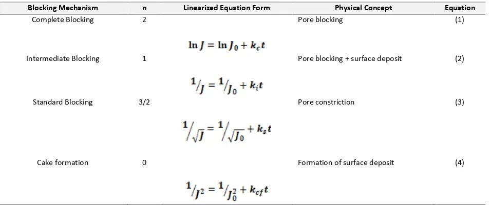
In order to evaluate the fouling mechanism, data of membrane flux was fitted with linearization of blocking mechanism by Hermia model as listed in Table 2.
Table 2 Linearized form of blocking mechanism by Hermia model
Blocking Mechanism n Linearized Equation Form Physical Concept Equation
Complete Blocking 2 Pore blocking (1)
Intermediate Blocking 1 Pore blocking + surface deposit (2)
Standard Blocking 3/2 Pore constriction (3)
Cake formation 0 Formation of surface deposit (4)
3. Results and Discussions
3.1. Flux and Rejection
Figure 2 shows the variation of normalized flux (J/J0) as function of oil types.
Figure 2. NormalilzedFlux Decline of Ultrafiltration of Oil in Water Emulsion at Different Oil Types
The figure illustrated that the use of mineral oil result on higher flux than the diesel oil. This is due to the high molecular weight of mineral oil which is higher compared to the diesel oil. Diesel oil has a chemical structure of
0 0,05 0,1 0,15 0,2 0,25
0 50 100 150
J/
J0
Time (minutes) Diesel Oil
C13H28 and C14H30 while the mineral oil having chemical structure of (CH2)n when n is in the range number of 20-40. As the molecular weight of diesel oil was smaller, the diesel oil molecule flow inside the membrane pore faster than the mineral oil molecule. Inside the membrane pores, there is an adsorption of diesel oil which is one of the cause of membrane fouling.
Adsorption of hidrophobic material such as oil at the solid membrane surface can take place due to [9]: 1. Monolayer adsorption (amphiphilic material at hidrophobic surface)
2. Multilayer adsorption (solute hidrophobic at solid surface) 3. Capilary condensation (hidrophobic solute at membrane matrix)
The oil attcahted into membrane pore wall can reduce pore diameter and cause pore blocking. In additian, the oil can be deposited at the membrane surface, generating a layer that being a dominant resistance of water or permeate transfer [6]. In addition, the presence of surfactant on feed has effect on reduction of permeate flux. The surfactant on feed can be in the form of oil droplet attachment, free surfactant or micelle surfactant.
Concentration of COD on feed and permeate as well as its rejection are shown in Table 3.
Table 3 COD Concentration on the feed, permeate and the rejection
Oil Types COD of Feed COD of Permeate Rejection
(mg/l) (mg/l) %
Diesel Oil 108.757,82 1,490.51 98,66
Mineral Oil 137.950,71 7,046.07 94,89
The results of COD rejection represents that the rejection rate is high, but the COD concentration is considerably higher that the regulation of COD limit due to very high COD concentration on the feed. However, since the rejection rate is more than 90%, it is certain that the membrane is appropriate for treatment of oily waste water to remove the oil or grease component.
3.2. Her ia’s Model a d Fouli g Mecha is s
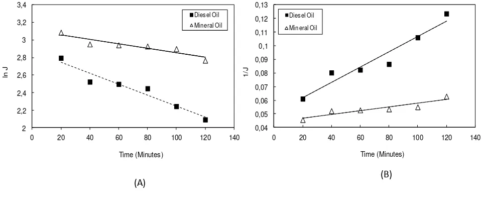
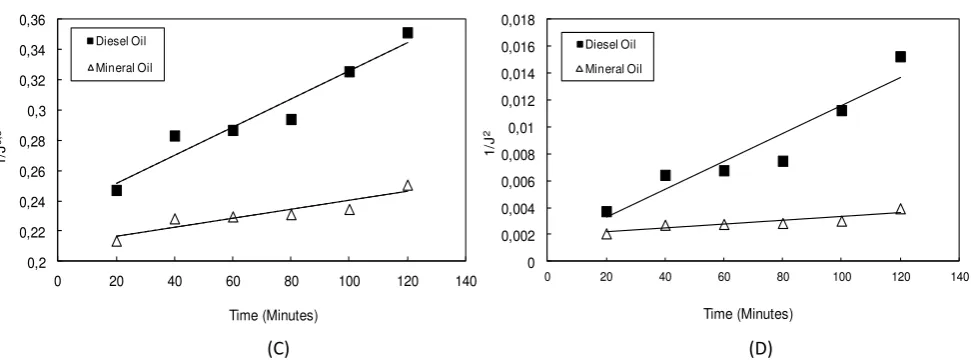
I thid study, Her ia’s odel as used i order to a alyze the fouli g e hanism during ultrafiltration of oil in water emulsion. The model fit was use to determine the cause of flux decline whether by cake formation or pore blocking. Figure 3 shows the fitting of blocking mechanism during ultrafiltration of oil in water emulsion based on
Figure 3. Effect of Oil Types to permeate Flux predicted by Blocking Mechanism: (A) Complete Blocking (B) Intermediate Blocking (C) Standard Blocking (D) Cake Layer
Figure 3 shows that the mineral oil seem to have good agreement with all blocking mechanism. On the other hand, the diesel oil only has good agreement with the Complete Blocking and Intermediate Blocking Mechanisms. In order to confirm the exact blocking mechanisms for both oil, value of R2 of the fitting model as well as value of
fitted para eter ere al ulated. The alue of R2 a d Fitted Her ia’s odel para eter are prese ted i Ta le 4
and Table 5, respectively.
Table 4 Values of R2 to the experimental data by effect of oil types
Oil Types n=2 n=1 n=3/2 n=0
Complete Blocking Intermediate Blocking Standard Blocking Cake Layer
Diesel Oil 0,9368 0,9296 0,9367 0,8985
Mineral Oil 0,851 0,8448 0,8489 0,8315
Table 5.Fitted Her ia’s Model Para eters for Differe t Oil Types
Oil Types kc ki ks kcf
Diesel Oil 0,0063 0,0006 0,0009 0,00001
Mineral Oil 0,0025 0,0001 0,0003 0,00001
Table 4 shows that both diesel oil and mineral oil having the greatest R2 value for Complete Blocking Mechanisms. Moreover, the value of fitted parameter as shown in Table 5 supports this statement. The greatest value parameter for diesel oil and mineral oil are both found for complete blocking mechanisms. The values of this parameter should be higher for the conditions that exhibit to more severe flux decline of the membrane. Since the mineral oil exhibits less fouling to the membrane, the value of kc, ki, ks, and kcf are lower compared to the diesel oil.
Based o the Her ia’s odel, oth diesel a d i eral oil ha e o plete lo ki g e h asi of fouli g. The complete blocking mechanism assumes that all the solutes participate in blocking the membrane pore but do not
overlapped upon one another.
4. Conclusions
is due to the small molecular size of diesel oil. The small molecule of diesel oil make it possible to go inside membrane pore and adsorp into pore membrane. The adsorption of oil droplet into membrane pore can generate the membrane pore blocking. This cause the membrane fouling and hence reducing the membrane flux. The use of ultrafiltration membrane for oily waste water treatment model achieve rejection of more than 94%. Analyze of
lo ki g e ha is usi g Her ia’s odel reveal that ultrafiltration of both diesel and mineral oil have good agreement with complete blocking mechanism.
Acknowledgement
The authors of this work wish to gratefully acknowledge the financial support of the Directorate of Higher Education through Stranas Research Project with Agreement Letter no. 008/SP2H/PL/Dit. Litabmas/III/2012.
References
[1] Ahmadun F, Pendasteha A, Abdullah LC, Biaka R A, Madaaeni SS., Abidin ZZ. 2009. Review Technologies for Oil and Gas Produced Water Treatment. J. of Hazardous Materials, 170 : 530-551
[2] Coelho A, Castro A V, Dezotti M, 2006. Treatment of Petroleum Refinery Sourwater by Advanced Oxidation Process. J.
Hazard.Matter, 137 : 174-184
[3] Chakrabarty B., Ghoshal A K, Purkait M K. 2008. Ultrafiltratio of sta le oil-in-water emulsion by polysulfone membrane.
J. of Membrane Science, 325 : 427-437
[4] Benito J M, Rios G, Ortea E, Fernhdez E, Cambiella A, Pazos C, Coca J.2002Design and construction of a modular pilot plant for the treatment of oil-containing waste waters. Desalination, 147 : 5-10
[5] Cheryan M. 1986. Ultrafiltration Handbook. Marcel Dekker, Technomic Publishers, Lancaster, Pennsylvania
[6] Benito, J. M, Ebel S., Gutierrez B, Pazos C, Coca J. 2001. Ultrafiltration of waste emulsified cutting oil using organic membrane, Water, air and solid pollution, 128: 181-195
[7] Amin I N H M, Mohammad A W, Markom M, Peng L C, Hilal N. 2010. Analysis of deposition mechanism during ultrafiltration of glycerin-rich solutions. Desalination, 261: 313-320
[8] Wang F., Tarabara V V. 2008. Pore Blocking Mechanisms during Early Stages of membrane fouling by colloids. J. Colloid
Interface Sci., 328: 464-469
![Figure 1. Blocking Mechanism by Hermia Model [7]](https://thumb-ap.123doks.com/thumbv2/123dok/1131755.653739/2.595.183.444.619.753/figure-blocking-mechanism-by-hermia-model.webp)