Current Density Performances in Poly Ether Ether Keton
Membrane for Direct Methanol Fuel Cells
T. D. Kusworo
*1, E. L. Dewi
2, D. K. Arti
1, A. Dhuhita
1A.F. Ismail
3and M.N.A. Mohd Norddin
31
Chemical Engineering Department, Engineering Faculty
Diponegoro UniversityProf. Sudharto Street, Tembalang, Semarang, 50239
2Agency of Assessment and Application of Technology 3
Advanced Membrane Technology Research Centre, Faculty of Chemical and Natural Resources Engineering, Universiti Teknologi Malaysia, 81310 Skudai, Johor, Malaysia
Abstract
The objective of this study focuses on the characterization of poly ether ether ketone (PEEK) membranes for direct methanol fuel cells (DMFC)
application. The PEEK membrane was modified with sulfonation in NMP solvent. The characterized of membrane were done using Scanning
Electron Microscopy (SEM), water uptake, methanol permeability, proton conductivity and DMFC test. DMFC tests were performed at room
temperature to obtain polarization curves that show voltages and power density of each variable. The results showed that the sulfonation of
PEEK method of the polymer increases water uptake. However, the methanol permeability and proton conductivity of membrane decreses. In
terms of morphology, it was found that sulfonation of PEEK method can be applied for membrane modification for DMFC application. In terms
of the DMFC tests of the membranes, SPEEK proved to have the best performance in stability because of its low methanol permeability.
Keywords: DMFC, PEEK, Polarization Curves, Proton Conductivity, Methanol Permeability,
1. Introduction
One of the most important challenges that our world will face in the twenty-first century will be continuing to meet the ever increasing energy needs of its citizens. Along with the need to find a renewable long term energy source is the need to find a more environmental friendly one. One of the promising candidates as a power source solution for the future world energy problem is fuel cell. A fuel cell is an electrochemical device that converts chemical energy directly into electrical energy from an electrochemical reaction. It produces electricity, water and heat from the reaction of fuel and oxygen without any burning thus greatly reducing the pollutants and inefficiencies brought about by combustion. Unlike dry-cell battery, fuel cell does not require recharging and operates as long as fuel is available [1-8]. The fuel is typically hydrogen.
The basic advantages of fuel cells are the potential for a high operating efficiency (up to 50-70%) and near zero green house emissions. Secondly, fuel cell systems provide quiet and vibration free operation. Thirdly, a fuel cell system is a highly scalable design. Finally, fuel cells have multiple choices of potential fuel feedstock from renewable ethanol to biomass hydrogen production and a nearly instantaneous recharge capacity compared to batteries [1-8]. Fuel cell could be used in many applications. Therefore, there are several types of fuel cell technologies being developed for different applications, each using a different chemistry, electrolyte used and
Corresponding author
o Telp/Fax : +62-24-7460058
their operating temperature. One of the promising types for small appliances and vehicle application is the proton exchange membrane fuel cell.
Proton exchange membrane fuel cells (PEMFC) are one of the most promising clean energy technologies under development. It has becoming increasingly important as alternative energy sources for stationary, automobile and portable power. The major advantages include: current prototype efficiency of up to 64%, high energy densities (relative to batteries) and the ability to operate on clean fuels while emitting no pollutants. This fuel cell type operates at relatively low temperature (30-150oC) but generate more power for a given volume or weight of a hydrogen-air fuel than any other type of fuel cell. In addition, proton exchange membrane fuel cells have drawn a lot of attentions because of the high efficiency, quiet operation, use of fuel from totally renewable resources, and environmentally friendly processes.
Despite these benefits, diffusion of PEMFC technology into the market place is being limited by cost and reliability issues. Recent research has attempted to tackle these problems with moderate success. As a result, it is widely acknowledged that the goal of large scale fuel cell market penetration in areas including transport have moved from 2010 to 2015, and that there are still many technical and social issues to overcome [9]. These challenges include: choosing the appropriate fuel (basically hydrogen) source and infrastructure, industry regulation, safety and public acceptance and hydrogen handling problem. Therefore, research into fuel cells has grown exponentially over the last 15 years. In case of polymer fuel cell, Direct Methanol Fuel Cell (DMFC) which does not use hydrogen as fuel is gaining more attention nowadays. Direct methanol fuel cell (DMFC) is a type of PEMFC that uses direct aqueous methanol solution as fuel. The methanol is fed at anode and oxygen at cathode, separated by a polymer electrolyte membrane. As the methanol fuel is directly fed to the anode, reaction occurs in the oxidation of the methanol into carbon dioxide (CO2), proton and electron. The released electron will travel
through an external circuit where electrical energy can be harnessed. Protons move from anode to the cathode via the polymer electrolyte membrane and combine with the oxygen and electron to form water [1-8]. Direct use of methanol in DFMC is a topic of considerable interest. Yet there are still a lot of obstacles that DMFC have to overcome in order to penetrate the commercialization. The most influential factor is its high cost and low power density. Its high cost is contributed mainly by its catalyst and the MEA parts which contain the high cost membrane however will not be discussed into greater detail. The relatively low power density or lower cell performance compared to PEMFC is caused mainly by the poor kinetics of the anode electro-oxidation of methanol, low membrane proton conductivity and by the crossover of methanol through the polymer electrolyte membrane. The slow oxidation kinetic of methanol to carbon dioxide is due to the formation of carbon monoxide as an intermediate which strongly adsorbs on the catalyst surfaceis however out of the scope of this study.
A primary criterion for choosing proton exchange membrane in DMFC is high in proton conductivity as well as low in methanol permeability. High proton conductivity is desired to transport as much proton as possible from anode to cathode in order to enhance its performance. Methanol crossover from the anode to the cathode is also detrimental for the DMFC performance as it reduces the coulombic efficiency and cell voltage, leading to an efficiency reduction down to 35% [9]. The key to resolving proton conductivity and methanol crossover lies mainly in the polymer electrolyte membrane which must be able to filter methanol but pass the proton through to the cathode.
Nowadays, the most widely use commercial polymer electrolyte membrane is Nafion produced by DuPont since 1992. Nafion is a plain perfluorosulfonic membrane that is thermally stable and is excellent for PEMFC because of its high conductivity. However Nafion is not suitable for DMFC applications, part from being costly, this type of membrane has high permeability towards methanol even at low temperatures, which drastically reduces the DMFC performance [10]. This is worsening by high water permeability in perfluorinated membranes that can cause cathode flooding and, thus, lower cathode performance which also contributed to lower DMFC performance. Moreover, Nafion will loss its mechanical properties at elevated temperatures.
electrolyte membrane, characterization of SPEEK membranes and current density and stability performance evaluation of SPEEK membranes for DMFC.
2. Experimental
Deuterated dimethyl sulfoxide (DMSO-d6 99.96 atom % D) was purchased from CDN Isotopes, Point-Claire,
PQ, Canada. N,N-Dimethylacetamide (DMAc, anhydrous 99.8%) and 1-Methyl-2-pyrrolidinone (NMP, anhydrous 99.5%) was purchased from Aldrich Chemical Company, Inc., Milwaukee, WI, USA. Poly(ether ether ketone) (PEEK), powder form (< 80 mm) was supplied by Victrex Inc., Westchester, PA, USA. Methanol, 99.9% and Sulfuric acid, 95-99% was purchased from Merck KGaA, Damstadt, Germany. Nafion 112 and Nafion 117 were supplied by DuPont.
2.1. Synthesis of SPEEK
PEEK was sulfonated following the technique described [9]. A 5g of PEEK was dried in a vacuum oven at 100C for 24 hrs and then dissolved in 95 ml of concentrated (95-98%) sulfuric acid (H2SO4) at room temperature
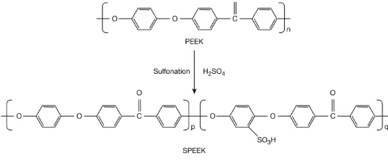
to suppress the heterogeneous sulfonation. After completing the dissolution of PEEK (about 1 h), the polymer solution was brought to the desired temperature of 55C and held for 3 hrs to obtain the desired degree of sulfonation (DS). In order to terminate the reaction, the polymer solution was poured into excess ice-cold deionized water under continuous stirring for one night to remove the residual acid. The polymer was washed repeatedly with deionized water until a neutral pH was reached. Then it was dried in air circulation oven at 60C overnight. The formation of SPEEK from PEEK is shown in Figure 1. The sulfonated poly(ether ether ketone), SPEEK, is basically a copolymer, consisting of sulfonated PEEK structural unit and original PEEK structural unit.
Figure 1: Sulfonation of PEEK
Membranes Preparation. Ten gram of SPEEK was dissolved in 90 g NMP to make a 10 wt% of original SPEEK solution. The blend solution was prepared by adding 0.4 g of cSMM, 9.6 g of SPEEK, and 90 g of the NMP solvent. Both mixtures were stirred for 24 hrs, before the mixtures were cast onto a glass plate using a pneumatic casting machine to a thickness of 1x10⁻⁴ m. The membrane was dried at 120C for 24 hrs in a vacuum oven. After cooling to room temperature, the membrane was peeled off from the glass in deionized water. Finally, the membrane was converted into the H+ -form by immersing it into a 1 M sulfuric acid solution for 24 hrs at the room temperature and blotted dry with absorbent paper before it was air dried.
Water Uptake of Membranes. Water uptake, which is used to determine the water content of the membrane in its wet state, is one of the fundamental measurements for DMFC electrolyte. The membrane was dried in an oven at 60C for 48 hrs, weighed, soaked in deionized water overnight at room temperature, blotted dry with absorbent paper to remove any surface moisture, and re-weighed. Then, % of water uptake was calculated from the equation below,
Water uptake %
100
dry dry wet
W
W
W
where Wwet and Wdry are the weight of the wet and the dry membrane respectively. The accuracy of the
measurement is within ± 3%.
Membrane Morphology. The morphology of the blend membrane was investigated using scanning electron
microscopy (SEM). Specimen for the SEM was prepared by freezing the dry membrane sample in liquid nitrogen up to 10 min and breaking it to produce a cross-section. Fresh cross-sectional cryogenic fractures of the membrane was vacuum sputtered with a thin layer of gold by using an ion sputtering (Biorad Polaron Division, Hertfordshire, UK) before viewing on the scanning electron microscope (SEMEDAX; XL 40; PW6822/10, Phillips, UK) with a potential of 10 kV.
Performance of Membrane as DMFC Electrolyte
Methanol Permeability of Membrane. A diaphragm diffusion cell, as described in detail elsewhere [12] was used to determine the methanol permeability of the membrane. The apparatus consists of plastic compartments (A and B), separated by the test membrane with an effective area of 2.5447x10⁻⁴ m2. The compartment A (V = 5x10⁻⁵ m3) was filled with 1M methanol and the compartment B was filled with distilled water. The methanol molecules diffuse along the concentration gradient through the membrane into the opposite compartment of the diffusion cell. Magnetic stirrer was used in each reservoir to ensure uniformity during the diffusion experiment. To determine the methanol permeability of each membrane, liquid samples of 500 µL were taken every 30 min from the permeate compartment using a syringe and the samples were then analyzed with a digital differential refractometer (Perkin Elmer, USA). Prior to testing, all membranes were hydrated in de-ionized water for at least 24 hrs. Methanol diffusion is induced by a concentration gradient across the membrane. Hence, from the change of methanol concentration in the diffusion reservoir the diffusion coefficient is obtained by equation (2) [12].
)
), CB is methanol concentration in diffusion reservoir (mol L -1
), D
is methanol diffusivity (m2 sec-1), K is partition coefficient and t0 is time lag (sec).
The time lag is explicitly related to the diffusitivity (t0 = L 2
/6D). Metha ol per ea ility τ is defi ed as the product of the diffusivity of methanol (D) and the partition coefficient (K; τ = DK. The methanol concentration in diffusion reservoir (CB)at t was calculated from the linear interpolation of CB versus t and the slope (m) of the
Therefore, equation (3) can be rearranged to calculate the methanol permeability as expressed below:
A impedance technique using a Solartron impedance-gain phase analyzer. The detail of the conductivity measurement is given in the earlier report [13]. The impedance spectra were recorded over the frequency range of 10 MHz to 10 Hz with 50 to 500 mV oscillating voltage. Membrane sample was equilibrated in deionized water for 24 hrs at room temperature prior to testing. Then, the surface water was removed, and the swollen membrane was rapidly placed between two stainless-steel electrodes in a conductivity cell (this cell is used to host the sample). The water content of the membrane was assumed to remain constant during the short period of
where L and S are the thickness and area of the membrane, respectively.
Electrochemical Measurements. DMFC tests were carried out in a 5 cm2 single cell using an H-Tech Inc. fuel cell test station. The fuel cell tests were carried out at room temperature. The polarizationcurves were recorded using a high power potentiostat (Wenking model HP 88) interfaced with a PC to apply the current sequences and to store the data, and a variable resistance in order to fix the applied current to the cell.
3. Result and Discussion
After casting on a glass plate, the membrane was more yellowish than the original SPEEK. Figures 2a and b show the SEM pictures of low and high magnification of the SPEEK membrane, respectively. Both membranes look similar with dense structures. In both, nodular structures are observed. Judging from the size of each spherical unit, it represents the super nodular aggregates.
Figure 2: Cross-sectional pictures of low magnification (a) SPEEK; (b) high magnification of SPEEK
Water uptake is used to determine the water content of the membrane in its wet state. Water uptake is related with conductivity of membrane. Table 1 shows the result of water uptake measurements. It shows that water uptake increased significantly from SPEEK compared to Nafion membrane. In SPEEK the sulfonate ions in the ion cluster domain are hydrated with absorbed water molecules [14]. The increase in water uptake means, therefore, the increase in the sulfonate ion density in the cluster. It is likely that the excess sulfonate ions are provided by the added cSMM.
Moreover, as reported in [15, 16], the water sorbed in the membrane can be categorized into two different groups; bound water and free water. The former is the state of water associated with the ionic site whereas the latter is present in the space between the sulfonic groups. In view of the dense structure of the membrane, the space between the sulfonic groups must be very small. Hence, water in the membrane is present most likely as the water bound to the ionic site. The increase in the amount of the sorbed water upon addition of cMMS is then due to the increase in the amount of the bound water.
Table 1: Characterization of Nafion 112 and SPEEK membranes
Membran Water
uptake
Methanol permeability (, cm2 sec-1)
Proton conductivity S cm-1
Nafion 112 20 6,21 x 10⁻⁶ 1,2 x 10⁻²
SPEEK DS58 32 4.15 x 10⁻⁷ 1,01x 10⁻²
Methanol permeability measurement is one of the fundamental tests of the membrane for DMFC application. Table 1 shows the methanol permeability of Nafion 112, SPEEK, and SPEEK/cSMM blend membranes. It can be observed from the table that the methanol permeability of the SPEEK membrane, 4.1510-7 m2 sec-1, is far less than the Nafion 112 membrane, 6.2110-6 m2 sec-1. Both values are considered acceptable as compared to other reported values [13]. Interestingly, the methanol permeability of the SPEEK/cSMM blend membrane, 5.1710-11 m2 sec-1, is even higher than the SPEEK membrane. The increase in methanol permeability is expected since the water uptake increased by blending cSMM. However, both methanol permeability and water uptake are determined by a delicate interplay of the porosity, the size of the hydrophilic/hydrophobic domain, and tortuosity.
The hydrophilic/hydrophobic domain behavior is noticed by other researches in nano-composite fuel cell membrane [17].
Table 1 shown that the Nafion membrane is the highest proton conductivity. Proton conductivity value is related to its water uptake. Addition of SPPEK will increase water uptake and its proton conductivity. Ionic conductivity for SPEEK is 1,01 x 10⁻² , respe ti ely. It sho s high o du ti ity’s alues for polymer hydrocarbon.
3.1. Effect of methanol Concentration and Catalyst Loading on SPEEK DS 58 Polarization Curves
The effect of methanol concentration and catalyst loading on current density (power density) of MEAs made with the investigated SPEEK DS 58 are shown in Figure 3a-b.
(a) (b)
Figure 3: Polarization Curve of DMFC using SPEEK DS 58 with (a) 1 mg/cm2 ; (b) 5 mg/cm2 catalyst loading
From the Figure 3, we can observe that there are difference polarization results between MEA with catalyst loading 1 mg/cm2 and 5 mg/cm2. In the 3 % methanol concentration, MEA with loading 1mg/cm2, can achieved power density value of 0.0058968 mW/cm2 with current deensity is 0.0451 mA/cm2, respectively. Meanwhile on the loading 5 mg/cm2, MEA only achieved power density value of 0.002649 mW/cm2 for 0.0227 mA/cm2 at 3% methanol concentration. MEA with lower loading of catalyst such as 1 mg/cm2 has been a better stability than MEA with higher loading of catalyst at the same methanol concentration. This phenomenon indicated that increasing of catalyst loading causes proton transfer via membrane is higher. Therefore power density of MEA with lower catalyst loading is higher than MEA with higher catalyst loading. As shown in the Figure 3, the 3% methanol concentration is the best concentration compare to the other methanol concentration.
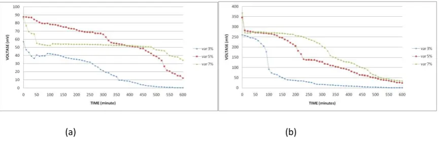
The effect of SPEEK DS58 membrane on stability by time for DMFC application was observed for 10 hours, respectively. The loading is fan that integrated to DMFC kit. Figure 4a-b was displayed the effect of of catalysts loading on the membrane stability.
(a) (b)
These plots show achieving voltage of DMFC and its stability for 10 hours. SPEEK with 1 mg/cm2 catalyst loading gave the best stability at 5% methanol concentration. Based on its polarization curves, it was gave the same result since polarization curves shows 5% methanol concentration achieved highest power density. Then, SPEEK with 5 mg/cm2 catalyst loading gave the best stability at 7% methanol concentration. This phenomenon can be explained by this way. Oxidation of methanol at anode caused decreasing of methanol concentration that crossing over from anode to catode. It means that methanol crossover will increase according to increasing of loading. When we used fan as loading, it means that we are using constant loading. SPEEK membrane will operate maximum at 7% methanol concentration for constant loading. For continuity addition of loading, methanol crossover will increase that effect to drop its voltage and power density.
3.2. Effect of methanol Concentration and Catalyst Loading on Nafion 112 Polarization Curves
The performance of SPEEK DS58 for DMFC application was compared with the Nafion 112 membrane. The effect of methanol concentration on the polarization curve of SPEEK DS58 membrane with catalyst loading 5 mg/cm2 is shown at Figure 5. The performance of Nafion 112 with 1 mg/cm2 loading catalyst cannot be characterized because the result of polarization curve was instability.
Figure 5: Polarization Curve of DMFC using Nafion 112 with 5 mg/cm2 catalyst loading
From the Figure 5, it seems that stability of DMFC using Nafion 112 with loading catalyst of 5 mg/cm2 will decrease because of increasing of methanol concentration. Methanol concentration of 3% and 7% become stable until current density of 0.0275 mA/cm2 and 0.0124 mA/cm2, respectively. The stability of Nafion 112 membrane decreases with increasing of methanol concentration. This phenomenon indicated that the peak of power density was achieved the maximum power of DMFC. Methanol concentration of 7% only result power density of 0.002337 mW/cm2. Methanol concentration of 7% is easier to crossover from anode to catode so its voltage is easier to drop. Increasing of methanol concentration will raise solubility of methanol in water, higher solubility will increase methanol crossover to catode side. Methanol crossover will decrease efficiency of DMFC and decrease power density.
Figure 6: Voltage vs Time Curve for Nafion 112 Membrane with (a) 1 mg/cm2 and (b) 5 mg/cm2 catalyst loading
Based on Figure 6, the best condition to operate Nafion 112 for DMFC is using 5% methanol concentration. Based on the results, we can concluded that the SPEEK DS58 membrane better performance in term of stability than Nafion 112. It shows by higher power density from polarization curves and higher voltage stability from 10 hours observation. Nafion 112 is easier to drop compare to the SPEEK DS58 membrane.
4. Conclusion
In this study, SPEEK DS58 was successfully synthesized in our laboratory. The synthesized of SPEEK increases of water uptake. However, the proton conductivity and methanol permeability was decreased. However, in term of current density, voltage and stability of SPEEK membrane was more better compare to Nafion 112 membrane. This phenomenon indicated that the SPEEK membrane is good to the other studied fuel cell that does not use methanol as its fuel.
Acknowledgements
The authors are thankful to the Agency of The Assessment and Application of Technology, Jakarta for their fellowship for research work at Fuel Cell Laboratory, TIEM, Jakarta. The authors gratefully acknowledge for granting the financial support from PKM Dirjen Dikti Republik Indonesia and Faculty of Engineering Diponegororo University.
References
[1] P.P. Kundu, V. Sharma, Y.G. Shul, Composites of proton-conducting polymer electrolyte membrane in direct methanol fuel cells, Crit. Rev. Solid State Mater. Sci. 32 (2007) 51.
[2] V. Neburchilov, J. Martin, H. Wang, J. Zhang, A review of polymer electrolyte membranes for direct methanol fuel cells, J. Power Sources 169 (2007) 221.
[3] H. Pei, L. Hong, J.Y. Lee, Embedded polymerization driven asymmetric PEM for direct methanol fuel cells, J. Membr. Sci. 270 (2006) 169.
[4] J. Meier-Haack, A. Taeger, C. Vogel, K. Schlenstedt, W. Lenk, D. Lehmann, Membranes from sulfonated block copolymers for use in fuel cells, Sep. Purif. Technol. 41 (2005) 207.
[5] L. Li, Y. Wang, Sulfonated polyethersulfone cardo membranes for direct methanol fuel cell, J. Membr. Sci. 246 (2005) 167.
[6] M.A. Hickner, H. Ghassemi, Y.S. Kim, B.R. Einsla, J.E. McGrath, Alternative polymer systems for proton exchange membranes (PEMs), Chem. Rev. 104 (2004) 4587.
[7] D.J. Jones, J. Roziere, Recent advances in the functionalisation of polybenzimidazole and polyetherketone for fuel cell applications, J. Membr. Sci. 185 (2001) 41.
[8] B.C.H. Steele, A. Heinzel, Materials for fuel-cell technologies, Nature 414(2001) 345.
[9] R.Y.M. Huang, P. Shao, C.M. Burns, X. Feng, Sulfonation of poly(ether ether ketone (PEEK): kinetic study and characterization, J. Appl. Polym. Sci. 82 (2001) 2651.
[10] E.L. Dewi, Sintesis dan Karakteristik Nanokomposit Membran ABS Tersulfonasi sebagai Material Polielektrolit, Jurnal Nanosains dan Nanoteknologi vol 2 (2009) No.1.
[11] M.H.D. Othman, A.F. Ismail, A. Mustafa, Proton conducting composite membrane from sulfonated poly(ether ether ketone) and boron orthophosphate for direct methanol fuel cell application, J. Membr. Sci. 299 (2007) 156.
[12] S.D. Mikhailenko, S.M.J. Zaidi, S. Kaliaguine, Sulfonated polyether ether ketone based composite polymer electrolyte membranes, Catalysis Today 67 (2001) 225.
[13] M.H.D. Othman, A.F. Ismail, A. Mustafa, Proton conducting composite membrane from sulfonated poly(ether ether ketone) and boron orthophosphate for direct methanol fuel cell application, J. Membr. Sci. 299 (2007) 156.
[14] P. Bebin, M. Caravanier, H. Galiano, Nafion® /clay-SO3H membrane for proton exchange membrane fuel cell
application, J. Membr. Sci. 278 (2006) 35.
[16] D.S. Kim, H.B. Park, J.W. Rhim, Y.M. Lee, Preparation and characterization of crosslinked PVA/SiO2 hybrid
membranes containing sulfonic acid groups for direct methanol fuel cell applications, J. Membr. Sci. 240 (2004) 37.