Proceedings of the 3rd
IMT-GT Regional Conference on Mathematics, Statistics and Applications Universiti Sains Malaysia
EFFECT OF WAVE BREAKER ON AMPLITUDE REDUCTION
OF THE INCOMING WAVE
1
Marwan,
1Said Munzir,
2Ichsan Setiawan,
1Rasudin
1
Jurusan Matematika
2
Jurusan Ilmu Kelautan
FMIPA, Universitas Syiah Kuala, Banda Aceh, Indonesia Contact person : [email protected]
Abstract. We consider a bar type of wave breaker. In this paper effect of such wave breaker on incoming wave is presented. The relationship formulation between height and width of the wave breaker with the amplitude of the wave is derived. The formula is derived for two cases of wave, i.e linear wave and dispersive wave. The formula is found by using the same analogy as well as grating phenomena in optic waves. The comparison of amplitude reduction of both waves is also presented.
Keywords : wave breaker, dispersive wave, amplitude reduction.
1
Introduction
The general characteristic of water wave is mainly influenced by the nonlinear behavior of the water medium. This characteristic causes the changes of water wave form as a function of position and time. In the wave travel, due to this characteristic, the wave amplitude is increasing as reported by [1,2,3,5,6,10]. This surely causes certain consequences over the beach condition if the wave travels toward the coastal area [7,8,9].
The damage caused by water wave is related to how far, big, and quick the wave motion when it reach the coast area. The damage is worse when the incoming wave is big and with high speed, like the tsunami wave occurred in December 2004 in Aceh and the area around it. This killing wave has taken 175.000 lives of the victims, while millions of others have to live in temporary shelters. Besides, Aceh coastal area along with its beautiful natural scene is totally damaged by the giant wave. Some references have estimated that the tsunami wave occurred in Aceh at the December 26, 2004, has the amplitude of 9 meters with the speed of 750 km/hr (see [19]). This kind of wave can destroy anything on it way. It is suspected that one of the factors that causes the severe damage by this giant wave is the unavailability of the wave breaker which can reduce the amplitude of the incoming wave at the beach. It can be obviously proven that in the more populated area (more building) the distance reached by the tsunami wave is relatively shorter than that of the empty area.
This research focus on the problem related to wave breaker design at the bottom of the sea which is directed to reduce the impact of the coming wave along the coastal line. These wave breakers, located at the bottom of the sea, functioned as an instrument to decrease the amplitude of the wave moving above them. This result is important to know, to give development direction and model application in the specific study which connect the real condition of abrasion and dissedimentation in the coastal area. The study here is conducted using the analogy of the grating phenomena in the study of optics. Here, two waves modeled are used: linear wave and dispersion wave. For dispersion wave, the model used is the Boussinesq equation with the exact dispersion relation.
This paper is organized as follows. In the section 2 the mathematical model used is presented. Monochromatic wave and the construction of wave reflector is presented in the section 3. Then, several graphical illustrations are presented in the section 4. Finally, the paper is ended with concluding remarks.
2
Mathematical Model
0
This equation is known as shallow water equation (SWE). Here x represent the spatial variable in the horizontal direction and z represent the spatial variable in vertical direction. h(x,t)is the water depth and η(x,t) is the wave elevation at the position x and the time t. Mean while, u(x,t) denote the water particle flow velocity component in the horizontal direction and g is the gravity accelerations.
Equation (1) is a simple form of the complete equation. After linearization, it gives [12]
0
represent the height of the water surface measured from the surface of the water at rest. By eliminatingu, this equation can be written as
2
where c2 =gH. Equation (3) is known as the one dimension wave equation having the solutionη(x,t)= f(x−ct)+g(x+ct). This solution represent the wave motion in two directions without changes in its form and having the velocity c. Such waves are called linear waves as it travels with a constant velocity gH . If the velocity does not only depend on the water depth but also depend on the wave length, the wave is also called dispersive wave. This type of wave can be modeled using the following Boussinesq equation [11]
where R denotes the differential operator having the Fourier symbol
k kH g
Rˆ = tanh( ). (5)
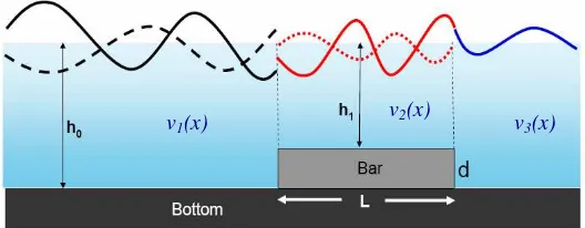
As this equation applied to the wave amplitude reduction as the result of installing a bar at the bottom, then the solution of equation (3) and (4) will be determined on three areas described in the Figure 1
Figure 1. The construction of the wave breaker building of the bar form
3
Monochromatic solution and reflector contruction
ℜ
Hence, the general solution of the equation (3) can be written as
)
where A,B∈ℜ. Equation (5) represents a monochromatic wave traveling in two direction having the constant velocity c.
Dispersion relation is a relation that must be satisfied between the wave number k and the angular frequency ω. Dispersion relation of the equation (3) can be obtained by substitution of the monochromatic solution
cc
Hence, it can be concluded that the solution of the equation (3) is a monochromatic wave traveling at the velocity c= gh0 if it move in the water having the flat bottom with the depth h0.
Furthermore, from the dispersion relation, it is well understood that the phase velocity depends on the water depth. The installation of a bar as a wave reflector will cause the differences of the incoming wave phase velocity. Assuming that the sea bottom as well as the wave reflector is flat, the water depth can be represented as the stair function. As the angular frequency ω is a fix given input, although the wave passing through the depth changing water, k is also a stair function.
The wave number k has piece wise constant value where discontinuities occurred at the points of the depth changes. For this piece wise constant k, the solution on each area having uniform depth of the water can be easily found. Then, adjusting and joining all the solutions in the whole interval will be conducted.
Natural phenomena show that water wave surface is always smooth although its bottom is not flat. In the other words, the smooth water surface is denoted by a continuous function. Meanwhile, slippery surface is represented by a continuous first derivative. However, according to the dispersion relation, if the wave reflector is installed, the wave number k is a stair function which is discontinue. Therefore, for the points of discontinuities, the following conditions should be added:
)
Similarly, as the travelling water wave surface is always slippery or does not have the slope change due to the changes of water depth, then at the discontinuities, the solution function must have the continuous first derivative with respect to x , i.e. Figure 1. Wave number k(x) will have a constant value in the interval between,
⎩
A : Incoming wave amplitude traveling to the right forx<0
r : Reflected wave amplitude traveling to the left for x<0 a : Wave amplitude traveling to the right for x∈[0,L]
b : Wave amplitude traveling to the left for x∈[0,L]
r
A : Transmitted wave amplitude traveling to the right for
x
>
L
0
h : Water depth when x∉[0,L]
1
h : Water depth when x∈[0,L].
If the incoming wave amplitude is given, coefficient a,b,r, Ar can be determined through the condition at
0
=
x and x=L. With the requirement that the solution and its first derivative must be continue, the condition at x=0 gives
According to the equation (9) and (10), it can be obviously seen that there are four equations with four unknown, i.e. a, b, r and Ar. Using the elimination method, it gives transmitted wave amplitude.
4
Graphical Illustration
In this section, several graphical representations based on the result obtained in the previous sec tion is presented.
Figure 2. Wave elevation at the surface having the bar at the bottom (top) and without the bar (bottom). (Left) for linear wave and (right) for dispersion wave
Figure 2 show the wave traveling with amplitude A=1.5m and frequency ω=2.2Hz. This wave travels at the water depth of h0=3 m. For this case, the height of the bar is chosen as d=1.75m and the width is chosen as
2
=
L m. It shows that the incoming wave (blue) amplitude is reduced after passing the bar (black). This occurred as part of the incoming wave is reflected (pink) and part of it is transmitted due to the bar placement (red). This can be compared to the wave elevation on the water surface without the placement of bar at the bottom. Here, it shows that there is no amplitude reduction.
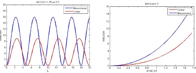
Furthermore, Figure 3 show the relation between wave amplitude reduction with the height d and the width
Lof bar.
Figure 3. Relation between wave amplitude reduction with the height (left) and the width (right) of bar.
The figure shows that the dependency of wave amplitude reduction over the height and the width of the reflector bar is having a similar pattern. The larger and the higher the reflector bar, the bigger reduction in the wave amplitude. Contrarily, The smaller and the shorter the reflector bar, the smaller reduction in the wave amplitude. In addition, it shows that the calculation using the dispersion model (red) gives larger amplitude reduction compared to using the linear model (blue). This gives indication that in addition to the depth factor, dispersion effect also influences the wave amplitude reduction.
5
Concluding Remarks
Acknowledgments
The authors would like to express their grattitude to Dr. Andonowati for her collaboration and cooperation on conducting this research. We would also like to thank Mathematics Department, Syiah Kuala University for the facilities we used in the Modeling and Simulation Lab. Finally, special honour for BRR NAD-Nias for financing this research in the financial year 2007.
References
1. C.T. Stanberg (1998), “On the non--linear behaviour of ocean wave gorups”, In: B.L. Edge and J.M. Hemsley (eds), Ocean Wave Measurement and Analysis, Reston, VA, USA : American Society of Civil Engineers (ASCE) 2, 1227-1241
2. E. van Groesen, Andonowati, E. Soewono (1999), “Non-linear effects in bi-chromatic surface waves”,
Proc. Estonian Acad. Sci., Mathematics and Physics 48, 206-229
3. Marwan dan Andonowati (2003), “Perubahan bentuk pada perambatan signal bikromatik dan pengaruhnya terhadap amplitudo maksimum”, JMS FMIPA ITB, Vol. 8 No. 2, 81-87
4. J.J. Wijetunge (2006), “Field in measurements in Sri Langka of maximum water levels due to Sumatera Tsunami of December 2004 and strategies for mitigating the risk from coastal hazards”, Proceedings of the Eleventh Asian Congress of Fluid Mechanics, Kuala Lumpur, Malaysia, 109-114.
5. J. Westhuis, E. van Groesen,R.H.M. Huijsmans (2001), “Experiments and numerics of bichromatic wave groups”, J. Waterway, Port, Coastal and Ocean Engineering 127, 334-342
6. Andonowati, E. van Groesen, “Optical pulse deformation in second order non-linear media”, Journal of Non-linear Optics Physics and Materials, 12, 221-234.
7. Klopman, G., M. W. Dingemans & E. van Groesen (2005), “ A variational model for fully non-linear water waves of Boussinesq type”, Proceedings 20th International Workshop on Water Waves and Floating Bodies,
ed. J. Grue, Spitsbergen, pg 129-132.
8. E. van Groesen and G. Klopman (2005), “Dispersive effects in tsunami generation”, Proceedings of The Indonesian Ocean Forum 2005, 13-15 July, Bali Indonesia.
9. O. Bokhove (2005), “Flooding and drying in finite-element Galerkin discretizations of shallow-water equations. Part I: One dimension”, J. Sci. Comput. 22, 47-82
10. E. Cahyono (2002), “Analytical wave codes for predicting surface waves in a laboratory basin”, Ph.D Thesis, Fac. of Mathematical Sciences Univ. of Twente, The Netherlands
11. E. van Groesen (1998), “Wave groups ini uni-directional surface wave models”, Journal of Engineering Mathematics 34 : 215-226