JOURNAL OF GREEN SCIENCE AND TECHNOLOGY
ANALYSIS OF THE STRUCTURE OF PLANNING OF K.H. MUHAMMAD
MACHDOR UNIVERSITY OF MUHAMMADIYAH CIREBON (UMC)
CONCRETE STRUCTURES USING SNI 2013
Ricki Saputra*, Sumarman**
*) Student of Civil Engineering Department Faculty of Engineering Universitas Swadaya Gunung Jati Cirebon **) Lecturer at Civil Engineering Department Faculty of Engineering Universitas Swadaya Gunung Jati Cirebon
ABSTRACT
Planning structure can be defined as a mix between art and science combined with intuition expert structure of the behavior of the structure with the basic knowledge in statics, dynamics, mechanics of material, and analysis, to produce a structure economical and safe, during services. (Agus Setiawan , 2008). Over time and the times in Indonesia humans can innovate to design buildings with some more modern building style. In addition in designing a building structure, we need a few materials that can be used as an ingredient implementation. Structural material that can be used includes wood, bamboo, concrete, steel, or any other supporting material. As well as on building construction projects K.H. Muhammad Machdor Universitas Muhammadiyah Cirebon Campus 2 by using concrete construction. Planning the contruction of its own building structure refers to the regulation SNI 1727-2013 and Pedoman Perencanaan Pembebanan Untuk Rumah dan Gedung 1987 regarding the imposition and use of seismic regulations stipulated in SNI 1726-2012. The preparation and the planning itself is assisted using modeling Extended Three Dimension Analisys of Building System ETABS v.9.5.0.
A. BACKGROUND
Universitas Muhammadiyah Cirebon (UMC) is a university private located in Cirebon, West Java, Indonesia. UMC was established on 28 September 2000 and managed by regional Ladership Muhammadiyah Cirebon. In the leadership meeting PDM/Cirebon December 8, 1999, agreed to establish The University Muhammadiyah Cirebon (UMC). Decision the meeting was then followed up by establishing a Board of Founders UMC, which soon consolidated, comparative studies and all the necessary preparations. The process of the establishment through Kopertis Region IV and the Director General of Higher Education through the stages is not easy. BP UMC hard work finally got the support of all parties. Muhammadiyah through the Higher Education Council then approved the establishment of UMC. Then on August 12, 2000 proclaimed the establishment of UMC with 8 Study Program D-III and S1. UMC establishment is then recognized and endorsed through a decree of the Minster Decree No. 203/D/0/2000 dated September 28, 2000.
Then the growing UMC hence the need for a building means supporting a learning process increased, too. Therefore perform the construction of buildings and other supporting lectures in various places belonging UMC Building one K.H. Muhammad Machdor UMC.
UMC’s building using concrete structure. On the basis of the safety criteria and excellent shall be in accordance with SNI 1727-2013 as well as the structural design of the building should refer to SNI-2847-2013 specification for concrete structural, other than that in the calculation of earthquake engineering should also refer to the SNI 1726-2013.
B. FOCUS ISSUE
In this study focused on designing and analyzing the main structure of the building construction of K.H. Muhammad Machdor Universitas Muhammadiyah Cirebon.
C. THEOLOGICAL ISSUES AND
IDENTIFICATION OF PROBLEMS 1. Problem Formulation
In a thesis with the title “ANALYSIS PLANNING BUILDING STRUCTURE K.H. MUHAMMAD MACHDOR UNIVERSITY OF
MUHAMMADIYAH CIREBON (UMC)
CONCRETE STRUCTURES USING SNI 2013” Will explain the problems that exist in the study area, so look for solutions to the problems. Thus the need for restriction of writing aimed at preparing the thesis, problem definition in the lift as follows:
a. Only the planning and design of construction Building K.H. Muhammad Machdor UMC in accordance with SNI-2847-2013 Concrete, PPURG 1987, and SNI 1727-2013 the form imposition of such plates, beams, columns, and foundation. b. Calculate the seismic forces that occur in the
structure of the building .
c. Not planning electrical installation, sanitary, and ceiling is
d. Not planned calculation steps. e. Analyzing the structure of building
2. Problem Identification
Based on the above background, the formulation of the problem can be identified as follows:
a. How the imposition of K.H. Muhammad Machdor UMC building using concrete structure SNI 2013.
b. How is the planning dimension of the plate, beams, columns, and foundation in building K.H. Muhammad Machdor UMC.
c. How to design a building K.H. Muhammad Machdor UMC.
D. RESEARCH OBJECTIVES
1. Analyze Building K.H. Muhammad Machdor Universitas Muhammadiyah Cirebon using concrete structures SNI 2013. 2. Gives an overview of design planning
E. PURPOSE OF RESEARCH 1. Theoretical Aspects
Of this research is expected to add to the mindset of students in learning, observing and understanding the issues related to the field civil engineering especially in construction building.
2. Practical Aspects
Of activity can be input for Building K.H. Muhammad Machdor UMC who have problems with the hope that the problems in these buildings can be overcome with good.
F. FRAMEWORK THINKING
A. REVIEW OF RELATED LITERATURE 1. PREVIOUS RESEARCH
Research has ever done before with case studies that have problems with analysis and discussion of the similarities which will be the subject of a reference in the preparation of which will be carried out, below there is a miraculous analysis of studies that have been done before, among others as follows:
First Planning conducted by Joseph (2015) conducted a Building Structure Development Planning. Title of research that Analisis Perencanaan Gedung Aula Dan Rektorat Universitas Swadaya Gunung Jati Cirebon Dengan Menggunakan Struktur Beton SNI 2013. The problems faced in the form of capacity building which is already insufficient to accommodate learners and the administrative needs of the University.
Both Planning made by Aries Saputra (2016) analyzed the structure of the form of construction of the hospital building. Title of research that Analisis Struktur Rumah Sakit Permata Cirebon. The problems faced in order to meet the lack of health infrastructure is lacking in Cirebon that carried out the construction of new hospitals such as Hospital Cirebon gem.
Third Planning made by Rury Mahendra Persada (2016) planning of planning on building construction, Grage. With the title of the research isAnalisis Perencanaan Struktur Hotel Dialog Grage Cirebon Menggunakan Struktur Beton SNI 2013. The problems that occurred in order to meet the needs of the community in the form of hotel infrastructure where the need for accommodation in the city of Cirebon is high enough to do the planning to the construction of the hotel.
B. THEORITICAL
1. Building
Based on the Law of the Republic of Indonesia No. 28 of 2002 on buildings. The building is a physical manifestation of the work of construction that blends with its domicile, partly or wholly on the top or in the ground that serves as a place of human activity, either for residential or residential, religious activities, business activities, social culture activities, as well as special activities. There is three chapters arrangement of buildings with the aim to a. Achieve buildings that are functional
b. Realizing the orderly organization of the building that ensures the technical reliability of buildings in terms of
safety, health, comfort, and
convenience.
c. Embody legal certainty in the
administration building.
Seven functions of the building pursuant to Article 5, right in paragraph 4 of which are on the market. Stating that buildings with business functions referred to in paragraph 1 shall include buildings for offices, trade, industry, tourism and recreation, terminals, and storage. purposes (SNI-1727-2013). Examples of the use of the structure include: the
1. structure of the building(building)used to shelter or activity.
2. The bridge structure(bridge)or tunnel (tunnel) that is used to connect one place to another place.
3. The structure of the dam, which is used for the storage and management / utilization of water, and many more forms of structure.
The structure is made of a material having mass, the structure will be influenced by its own weight. Self-weight of the structure and the structural elements referred to as the dead load. Besides the dead load, damaging environmental conditions (eg, the effect of chemicals, moisture, or corrosion). In reviewing a burden, we should not only determine the amount or intensity, but also need to review under what conditions the load applied to the structure.
In connection with the elastic properties of the material structure, every system or structural element will deform when loaded and will be returned to the original when the work load is removed. Therefore, the structure has a tendency to sway laterally (slideway), or bend down (deflection) when loaded.
b. Dead Load
Dead load is the weight of all parts of a building that is permanent, including any additional elements, settlement-completion, machinery and fixtures that are part and parcel of the building. (Muntohar, 2007)
For the purposes of analysis and the design of the building structure, the amount of dead load should be estimated or determined in advance. Dead loads are loads that work down at the structure and have the characteristics of the building, such as floor coverings, mechanical devices, and partitions. The weight of these elements, in general, can be determined easily with a fairly high degree of accuracy. To calculate the amount of dead load an element is done by reviewing the unit weight of the material is based on volume elements. The unit weight (unit weight) of material empirically determined and listed many tables on a number of standards or construction materials and components can be determined by the building regulations in
Indonesia, namely PPPURG 1987.
1. Building Materials
2. Building Components
c. Expense Life
Expense life is a burden caused by residential / use of a building and its depth including the loads on the floor coming from items that can move, machinery and equipment that are part of the building that is inseparable from the building and can be replaced during the life of the building , resulting in a change in the loading floor and the roof. (Supriyadi, 2007)
Especially in the roof into the live loads may include loads which come from rain water, either due to inundation or due to hit falling (kinetic energy) of water droplets. Into the live load does not include wind loads, earthquake loads and special loads. From this description, it is clearly impossible to review separately all loading conditions that may occur. Therefore, it is used a statistical approach to define the burden of this life, as an evenly distributed static load that is safe to be equivalent to the weight of the usage centrally expected maximum for a particular application.
The actual live load actually acting on the structure are generally smaller than the planned live load weighing on the structure. However, there is live load magnitude cooperation with the design load on the structure. It is clear that the structure of the building has been planned for a particular use should be re-examined when the powers will be used for other purposes. For example, a building which was originally planned for the apartment will not be strong enough when used for the building or the market.
The amount of live load evenly distributed equivalent to be reckoned with in the building structure, can generally be determined based on the applicable standards. In planning the development of Building K.H. Muhammad Machdor UMC application of living expenses adjusted to the function room which is already planned, in this case refers to the imposition of SNI -1727-2013 for buildings are as follows:
d. Expenses Earthquake
Expenses earthquake is a
on the surface of the earth (Himawan Indarto, 2009).
Magnitude earthquake loads on structures depend on several factors, namely: the mass and stiffness of the structure, nature and shakes a damping effect on the structure, soil conditions and seismic region where the structure is established.
▪ Earthquake region
Figure 2.1: Map of Land Seismic Motion and Risk Coefficient
▪ Category Buildings
On each building must be recognized in the category of one of the 4 categories of the building on SNI 03-1726-2012 chapter 4.1 Table 1 for the different categories of buildings and buildings used for calculating the load Face earthquake (V). For example, for buildings used as residential, commercial and office buildings, the primacy factor I = 1
Source: SNI 03-1726-2012 ordinance
earthquake planning for the building structure and non-building
▪ Ductility Building Structures
Ductility structures wear two
parameters, the ductility factor μ, and the deviation reduction factor R and the deviation in the first melting R. Deviation ductilityμ is the ratio deviations on the verge of collapse 𝛿𝑚 is the ratio of the load, earth quake plan,
and nominal earthquake loads. R is also an indicator of the ability of the ductility of the structure of the building. Μ value and R listed on SNI 03-1726-2012.
For example:
For structures with the structural system that basically has loadbearing gravity, space frame is complete. Lateral load on the structure is carried by the frame bearers bending moment mainly doing the mechanism and the system is intermediate concrete moment frame bearers (SPRMM), then the reduction factor used is 5.5.
▪ Earthquake Response Factor
Earthquake response factor (SA)
expressed in gravitational acceleration value depends on the time of natural shakes the building structure and the curve is displayed in the spectrum of response the earthquake plan.
Earthquake response factors specified in Figure 2.2 SNI 03-1726-2012. In the picture is the response factor earthquake SA stated in the acceleration of gravity and T is the time of natural shakes the building structure is expressed in seconds.
For T = 0 is equal to the value of SA Ao, where Ao is the peak acceleration of ground level according to table 5. SNI-03-1726-2012.
Figure 2.2 Earthquake Response Spectrum
The structure is modeled in 3 dimensions by including structural elements such as columns, beams, and plates. Concrete slab modeled as the rigid diaphragm that serves to distribute earthquake forces to other structural elements and wedged full on beam.
The columns are considered full wedged at the bottom. To ensure that it is provided sloop beams connecting the columns of the bottom.
The burdens of gravity (dead and live load) are transferred from the plate to beam, then distributed to the column.
The structure and components of the structure are planned until all cross sections have strong minimum plan together with a strong need to be calculated based on a combination of load and factored in accordance with the regulations
f. Software Used In Structure Analysis Authors in the analysis of this structure using statistical software extended Three Dimension Analysis of Building System ETABS v.9.5.0. ETABS is one of the applications are very popular in the world of civil engineering. software made CSI Berkeley is indeed very powerful in making structural modeling, analysis, and design. Most planners high rise building make ETABS as the first and foremost choice in performing dynamic analysis, dynamic analysis, because it is somewhat, takes time and sweat excessively if attempted manually counted. Dynamic analysis is not as simple as static analysis that simply relies on force equilibrium concept only.
A. METHODS
The study design begins with collecting and studying literature relating to planning. Collect data to be used as data in the object. The data used in this study as follows: a. Finding data in the form, existing data in the
form of a ground area of the building area and the function of the building to be the planned.
b. study of literature by collecting references and methods required for a review of the
literature from the book and other media (internet).
c. Processing and analysis of the data obtained.
d. Building Planning KH Muhammad Machdor
UMC.
e. Loading SNI 2013 (SNI-1727-2013), SNI Reinforced Concrete (SNI-2847-2013), and SNI imposition PPPURG -1987
f. Decision conclusions and recommendations of the study results
B. STAGE OF RESEARCH
Research methods used are quantitative and qualitative methods, understanding like this :
a. Quantitative method is a method that is done by collecting and studying literature relating to planning.
b. The qualitative method is a method that is done by collecting data to be used as data in the object.
To facilitate the step - step preparation of this final assignment methodology that aims to direct and streamline the time and the results to be achieved as follows:
1. Preparation
The preparation stage is the initial stage before starting action of an idea. Preparations in the form of a survey on the location of the Building K.H. Muhammad Machdor UMC.
A survey done is to review the location and retrieval of documentation in the form of photos - the photos to learn more about the location of planning.
2. Phase Identification of Problems
From the visual observation or survey research sites gained some problems that can be encountered, as follows:
a. How does the design of K.H. Muhammad Machdor UMC building using concrete structure according to SNI 2013?
b. How is the planning dimension of the plate, beams, and columns refer to the SNI 2013?
3. Phase Study Library
Literature study was done of the collection of the various theories relating to the condition and existing problems. The literature used according to the needs at the present time. This literature study reviews more fully in chapter II in this final report.
4. Stage Data Collection
Data collection phase has been reviewed in chapter III.
5. Phase Analysis and Data Processing
The data were then analyzed using a theory that has been determined in the study of literature. The results of the analysis and processing of this data will determine how
much influence the making of K.H.
Muhammad Machdor UMC Building. When the influence brought about favorable than the conclusion that the development of Building
K.H. Muhammad Machdor UMC, the
necessary planning as a function of the building. The calculations will be done using theoretical formula - a formula specified in the chapter literature.
The designs are created using a portal system using concrete structure. Building construction stage design calculations KH Muhammad Machdor UMC is as follows: a. Calculation of imposition of
b. building structures Designing the K.H. Muhammad Machdor UMC calculation reinforcement.
c. Foundation Calculation d. Calculation earthquake
C. TYPE AND DATA SOURCES
Various types and sources of data as follows:
a. Primary Data. In this study, the primary data collection is to conduct field surveys, the
research object in Building K.H.
Muhammad Machdor UMC. b. Secondary Data.
1.
Method Literature. The process of collecting data derived from reference books, journals - journals that exist in the Internet and related institutions in the form of a data area to be in his management analysis, and data such as pictures of the building to develop the data. Such data will be used for the preparation of the thesis.2.
Documentation methods. The datacollection includes pictures - pictures or documentation which is planned by the author on the object under study. The documentation obtained from the camera that is used to help manufacture thesis. related with planning construction of the building.
b. Observation method
Observation method is data obtained from the survey results directly to the location. With this direct survey can be seen directly in field conditions in order to obtain a picture that can be taken into consideration in building design plan K.H. Muhammad Machdor UMC.
c. Interview method
Interview method is data obtained by interviewing sources to get some information that can add ingredients in the preparation of building plans K.H. Muhammad Machdor UMC.
E. DATA ANALYSIS METHOD
reviews will be more detailed and specific so that the necessary chapter in efforts conclusion.
The stages of data analysis used in this paper are as follows:
a. Calculation of load 1. dead load 2. live load
3. Expenses Structure 4. Expense Earthquake
b. Calculation of building structures 1. Plate Dimensions
2. Dimensions beams. 3. Dimensions column and 4. foundation
F. LOCATION RESEARCH AND TIME
RESEARCH
1. Research Sites
Research Sites Building Project K.H.
Muhammad Machdor Universitas
Muhammadiyah Cirebon
Figure 3.1 Location Research
A. DISCUSSION AND RESEARCH
Analysis of building structures Building
K.H. Muhammad Machdor Universitas
Muhammadiyah Cirebon (UMC), performed by a computer-based finite element(finite element)to various loading combinations that include dead loads, live loads, and seismic modeling 3-D structure(SPACE-frame).Program structure modeling is done ETABS v9.5.0 (Extended Three- Dimensional Analysis of Building System)as shown in Figure 4.1.
Figure 4.1 Structural Modeling UMC Campus Building II
B.
STRUCTURAL DESIGNthe planned building consists of 4 (four) floor and using Dak Roof based on data from the previous chapter with the planning of the building to be used as a teaching and learning building on Campus 2 UMC.
From the analysis, the development of K.H. Muhammad Machdor UMC Building is very important to support teaching and learning activities as well as lectures and other activities that take place in the building tribute, which is expected by the realization of this project will create teaching and learning more effective.
And in planning and building Building K.H. Muhammad Machdor UMC uses the structure of concrete, as well as implementing ISO 2013 and an additional form of dead load PPPURG 1987 in reference to the loading obtained using the structural profile on the construction of Campus Building UMC is:
1. Plates
2. Beams and Columns
In planning beams and columns, the same as the loading plate is based on the use or usefulness, and adapted to ISO - 1727 - 2013 as well as the expenses of the Dead uses PPPURG 1987. The calculation process beams and columns can be found in the annex and to the dimensions of beams and columns can be seen in the table below:
C. REGULATIONS AND STANDARDS
1. Imposition Planning Guidelines for Home And Building (PPPURG 1987). 2. Earthquake Planning Procedures for
Building Structures and Non-Building (ISO-1726-2012).
3. The minimum load for Design of Buildings and Other Structures (ISO-1727-2013).
4. Requirements for Structural Concrete Building (ISO-2847-2013).
D. CHEMICAL STRUCTURE
1. Concrete
For all the structural elements of the columns, beams and plates used concrete with the compressive strength of concrete at Campus Building II UMC:
● Column Top 50 x 70 (24D22)
● Column Top 2 50 x 50 (20D19)
● Beam Master Pedestal and Fields 35 x 70
● Parent beam 2 30 x 60
● beam Kids 2 25 x 50
● fc '= 25 MPa.
● The elastic modulus of concrete, Ec = 4700.
√fc '= 23500 MPa = 23.5 million kN / m2.
● Figures poison, ς = 0.2
● shear modulus, G = Ec / [2 (1 + ς)] =
9791666.7 kN / m2
2. Reinforcement Steel
● Reinforcement for stirrup iron
columns and beams wear Ø12 with yield stress, fy = 400 MPa = 400000 kN / m2
● reinforcement for stirrups practical field wearing iron Ø12 with yield stress, fy = 400 MPa = 400000 kN / m2
● Reinforcement main column wear
iron O16 with yield stress, fy = 400 MPa = 400000 kN / m2
● Reinforcement main beam wear iron O16 with yield stress, fy = 400 MPa = 400000 kN / m2
● Reinforcement for plate wear iron ø 10 with a yield stress, fy = 400 MPa = 400000 kN / m2
3. Input Data structural materials
Figure 4.2 input structural Materials
E. STRUCTURAL ANALYSIS
1. Regulations Used
Before analyzing the structure, necessary to make adjustments concrete construction planning parameters according to the American concrete Institute (ACI 318-99) against the "Requirements for structural concrete Building (SNI 2847-2013)" Article 9.3.2. The difference should be adjusted is the reduction factor for SNI Concrete Indonesia. Differences in the reduction factor for the still weak level of employment and quality control and construction projects in Indonesia. Adjustments can be made by Options - Preferences - Concrete frame design. Strength reduction factor used for concrete construction planning to bending and tensile (bending) was taken 0.85 and for shear (shear) is taken 0.75.
Figure 4.60 Difference Reduction Factor SNI Concrete
2. Sectional Effectiveness
In concrete cracks of concrete structures, influence must be weighed against its rigidity. Thus, the cross-sectional moment of inertia of the structure can be determined at the moment of inertia of the
whole cross section multiplied by the percentage of the effectiveness of cross-section based on ISO 2847-2013 Section 10.10.4.1 Concrete as follows.
● beam Ig= 0.351
● Column = 0.701Ig
● structural walls = 0.351Ig
the percentage value the
effectiveness of the cross-section is inputted to ETABS by way Define - Frame Sections - Modify / Show property - Set Modifiers.
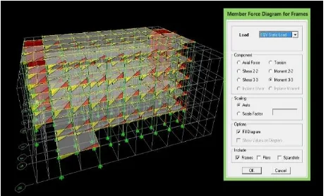
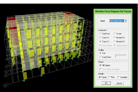
3. Style Analysis In
The analysis to determine the amount of force in the form of moments and shear forces can be done by Analyze - Run Analyze. Then Display - frames / pier / spandrel force.
● Axial Force: to show the axial forces.
● Shear 2-2: to show the shear forces on the axis 2-2.
● Shear 3-3: to show the shear forces on the axis 3-3.
● Torque: to show the magnitude of the torque.
● Moment 2-2: to show the moment on the axis 2-2.
● Moment 3-3: to show the moment on the axis 3-3.
● Fill Diagram: to display colors on the moment and shear force diagrams.
● Show Values on Diagram: to show the value at the moment and shear force diagrams.
The moment caused by the earthquake direction X by the method of equivalent static, response spectrum and time history as shown in Figure 4.64 to 4.69
Figure 4.65 Moment Y direction due to the earthquake response spectrum
Figure 4.66 Moment Y direction due to the earthquake (Time History El Centro) at 2,5
seconds.
Figure 4.67 Y direction shear force due to the earthquake equivalent static
Figure 4.68 shear force Y direction due to the earthquake response spectrum
Figure 4.69 Style sliding direction Y due to the earthquake time history when 2.5 sec
Of the three methods of analysis concludes that the results are not much different, just on analysis earthquake with a static equivalent results the moment and shear force is greater than method the response spectrum and time history.
1. The foundation design
the foundation used is the
foundation pile (bore pile).Description of soil data and calculation of the carrying capacity of the foundation is described as follows:
a. Land Data
Figure 4.89 Sondir Test
b. Capability Drill Piling Mast
Carrying capacity comprises axial pole carrying capacity of the base of the pole and the carrying capacity of the pole circumferential surface friction, reduced the weight of its own pole by the formula:
Qu = Qd + Qg - W
Qijin = (Qd + Qg) / FK - W Where:
Qu: bearing capacity of the pole, Qd: bearing capacity of base pole, Qg: bearing capacity of friction pole, W: weight of its own pole,
FK: pole safety factor = 3.
c. Column Edge carrying
The capacity of the pile for several conditions are as follows.
i) For non-cohesive soil
Qd = 40 Nb Ap (tons): According to Mayerhoff (1956)
ii)For the basic foundations below the groundwater table:
Nb '= 15 + 0.5 (N-15) iii) For sandy soil N> 50
Qd <750 Ap (tons): Suyono
Sosrodarsono and Kazuto Nakazawa Description:
Nb: N-SPT prices on the pole base elevation <40
Ap: basic sectional area of the pole (cm2)
d. Carrying Capacity of Friction Column
i) According Meyerhoff:
Qg = 0.20 O Σ (Ni x Li) (tons): to pile
Qg = 0.10 O Σ (Ni x Li) (tons): to pile
ii) According Suyono Sosrodarsono and Kazuto Nakazawa:
Qg = O Σ (Ni / 2 x Li) (tonnes)
Description: Ni / 2 <12 t / m2
O: around the cross-section of the pole Ni: N-SPT segment i pole
Li: the length of the segment i pole
Table 4:22 Strong support Foundation Bore Pile with Different Diameter
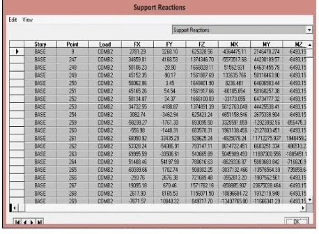
The value of the load point of the foundation can determine by Run - Display - Show Tables - Analysis Results - Reaction - Support Reactions.
Figure 4.90 a number of expenses of Table Base Point Support Reaction
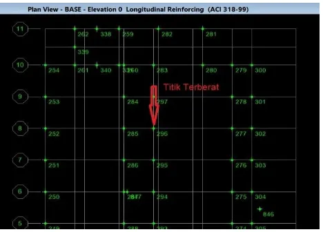
Figure 4.91 Location of Point - Point Foundation
From the results of the analysis, the result for the foundation point load of about 196.89 tons for the largest. Based on Table 4:22 if used foundation pile bore diameter of 60 cm, the foundation bearing capacity is 103.47 tons.
● The number of foundation piles for the load 196.89 ton = 196.89 / 103.47 = 1.903 So use two poles.
Figure 4.92 Location of Point - Point Foundation
A. CONCLUSION
After analysis and design of the
building structure K.H. Muhammad
Machdor Universitas Muhammadiyah
Cirebon (UMC) adjusted for Earthquake Planning Procedures for Building Structures
and Non-Building (SNI-1726-2012),
Minimum Load Requirements for Designing Buildings and Other structures (SNI-1727-2013) mainly live load and Requirements for structural concrete Building (SNI-2847-2013), it can be concluded as follows:
1. On Campus II building projects UMC entirely using concrete structure began of columns to the beams and roof and floor plates are used.
2. Planning four-story building on Campus II UMC assisted by software ETABS structure in analyzing the data.
3. Planning four-story building Campus Building II UMC is using column
reinforcement, so that the dimensions of columns and beams Campus
Building II UMC considered
appropriate where the dimension list of columns and beams UMC Campus
II is located at Chapter 4 page 61.
4. From the results of calculations on the floor wearing a reinforcement plate Ø 10-200 and 8-175 roof plate with fy 400 mpa. For the joist and beam using reinforcement D16, D19, D22 and for shear reinforcement within, 100mm, 125mm. The calculation of the wear reinforcement column D16, D19, and D22 with shear reinforcement within 125 mm with fy 400 mpa. Dimensional reinforcement for the D22 does not correspond to the dimensions of reinforcement on the field, because the field is only used for the column using an iron reinforcement 19 with fy 400 mpa and iron 16 with fy 400 mpa, and to beam using the same reinforcement. So that the dimensions of reinforcement columns and beams
UMC Campus Building II is
considered less worthy, while
reinforcing slab and the roof has been worth it. For a list of columns and
beams after analysis contained: an
image attachment.
196.89 tons. For the calculation of
foundation found in Chapter 4 page
147 and its foundation is on the floor
plan: an image attachment.
6. Results obtained in the form ETABS data analysis using Microsoft Excel calculation output in an attachment that can be used as a parameter in the structural design of the building.
B. RECOMENDATION
1. Before planning or redesign a building structure should we know in advance what kind of material structure and regulatory structures used in the structural design so that later we can easier to find and literature references which would help planning we do.
2. In doing data input on program ETABS should be done carefully in accordance with the assumptions that have been predetermined so it can produce structural
analysis approaching the actual
circumstances and should use software application structure analysis coupled with a manual count as a comparison, the structure of how good estimate of the structural elements will be used later not planning and calculation and profiles used should begin on the ground floor up to the roof so that the results of different loads such as axial force and torque generated is not too large which will have an impact on the budget plan.
5. In planning the foundation should use a type of foundation that is effective and efficient as the authors use the form bore pile foundation and if possible longer is able to use the stake, but it will affect the
surrounding environment as a result of vibration generated prayer.
6. Then after the planning and design have been completed it is better we do control the count analysis can be done using auxiliary systems such as Microsoft Excel to assist in processing the data, Mekanika Struktur. Yogyakarta: Graha Ilmu.
Arka Reka Struktur Grup. 2014. Aplikasi Perencanaan Struktur Gedung dengan ETABS. Jakarta: Arka Reka Struktur Grup.
Badan Standardisasi Nasional. Beban minimum untuk Perencanaan bangunan gedung dan struktur lain (SNI 1727: 2013)
Badan Standardisasi Nasional. Persyaratan beton Struktural untuk Bangunan gedung (SNI 2847: 2013)
Badan Standardisasi Nasional. Tata Cara Perencanaan Ketahanan Gempa Untuk Struktur Bangunan Gedung dan non-Gedung (SNI 1726: 2012)
Departemen Pekerjaan Umum. Pedoman Perencanaan Pembebanan Untuk Rumah dan Gedung (SKBI - 1.3.53.1987)
Jalaludin, Umar. 2008. Teori Mekanika dan Analisis Kekuatan Bahan. Yogyakarta: Pustaka Pelajar.
Persada, Rury Mahendra. Analisis Perencanaan Struktur Hotel Dialog Grage Cirebon Menggunakan Struktur Beton SNI 2013.
Saputra, Aries. Analisis Struktur Rumah Sakit Permata Cirebon (Skripsi) Universitas Swadaya Gunung Jati Cirebon. 2016.
Wesli. 2012. Mekanika Rekayasa. Yogyakarta: Graha Ilmu.