Implementation of Fuzzy Logic Control Algorithm
in Mobile Robot Avoider by Using Omnidirectional
Vision
Rossi Passarella, Kemahyanto Exaudi*, Sutarnoand Mas Sunardi
Department of Computer Engineering, Faculty of Computer Science, Sriwijaya University, Palembang 30139, Indonesia [email protected]*
Abstract:Mobile Robot avoider is one of the mobile robot that has capability for moving or maneuvering to avoid obstacles. To do this, mobile robot used many sensors to identify surrounding environment. One of the sensors that can be used in mobile robot avoider is a camera. However, the camera sensor still has a limited viewing angle, to reduce this limitation, we develop a System omnidirectional vision which is a system that capable of providing 360° angle information with just one image so that it can reach the surrounding circumstances. The speed and movement of the robot avoider set automatically by adopting the method of fuzzy logic. In this research, the testing phase is done 2 times on the track corridor of the swivel. The test results show that the mobile robot is maneuvering very well.
Keywords: Fuzzy logic, Mobile robot avoider, Omnidirectional vision
1. INTRODUCTION
Current robot technology always involves in human role. Most of the field work slowly being replaced by robots. Robot avoider is one example of the development of robot technology which can be programmed to avoid obstacles [1]. To be able avoid obstacles, robot avoider requires a sense of vision in the form of sensor.
The camera sensor basically has similar characteristics to the human visual perception. Like the human eye, the angles can be captured by the camera is similar to the human eye point of view that is the direction in which the camera is facing. To find out the circumstances surrounding the camera, The Omnidirectional Vision system is used. This system can provide an angle of 360° with a single image. The system can also be made by pointing the camera towards a convex mirror which can provide information such as distance, angle, object type and speed [2]. Setting the pace and movement of the robot requires a method to regulate the movement of the robot properly. In this paper, Sugeno Fuzzy Logic methods has been used
2. THEORY
A. Robot AvoiderIn general robot avoider designed using 3 distance sensors. But to design robot avoider that uses an omnidirectional vision
system only requires one camera as a sensor. B. Digital Image
The digital image is image data in a number representing the level of gray (image in black and white) or color coordinates (color image). In general, digital image has a certain length and width expressed in pixels, so that the image size is always rounded. Computers store only numerical data that show great intensity of each pixel. Digital image obtained through the sampling process three-dimensional object by an image capture system which then formed a matrix in which the elements value of the intensity of light [4].
C. Fuzzy Logic
2
Fig.1 Block Diagram of Rule Based Fuzzy System
3. METHODS
In this study, the design of the system is divided into two main parts: hardware design and software design. Both parts are then integrated to produce a system that is interconnected. A. Hardware Design
Hardware design phase is done in 2 stages: design robot avoider and camera placement and design of glass omnidirectional vision. There are several devices that are used in the design robot avoider using omnidirectional vision, namely wireless cameras, PC / Laptop, microcontroller and DC motors. Fig 2 shows the Block Design Robot avoider using omnidirectional vision.
Fig. 2 Block Design Robot avoider using omnidirectional vision
Wireless camera which is used as a sensor used to capture the image around and used as input. Images are captured are sent and processed directly on the computer. Computers are used to perform image processing to produce a pixel value. The pixel values are then sent to the microcontroller on the robot avoider to be forwarded to the motor.
The design of the camera position and the glass omnidirectional vision must be done accurately. This is done to get a proper perspective and spacious. The position of the camera facing up and placed on the side of the ring-shaped robot. While the convex mirror mounted just above the camera. The design of the camera position and the mirror can be seen in Fig 3.
Fig.3. The design of the camera position and mirrors
In a normal camera viewpoint is still not widely produced and still does not meet the data needs to capture the entire image environment, then the omnidirectional vision system is able to provide a field of view(FOV) is greater for the camera.
B. Software Design
Software design in this study consists of two parts, the design of the program for image processing and design of
algorithm’s fuzzy logic.The block diagram for software design
is shown in Fig 4.
Fig. 4. Block Diagram of Software Design
Image Processing
Stage image processing consists of several parts, among others, to get digital images (original), changing the original image into grayscale, change the image grayscale into a binary image by threshold method, the zoning and get the distance obstacle sensor. Stages of image processing stages can be seen in Fig5.
Fig. 5. The stages of image processing
Sensor Regional Distribution
At this stage robot standpoint of 180° is divided into 3 parts. Each section is divided into six laser angle to within 10° angle. Pictures of districts every 100 to the front can be seen in Fig 6.
Fig. 6 Distribution region Each 10 Degrees Forward
Fig 6 shows that there is a laser at a different angle laser blue, green and red. Blue laser sensors to indicate the left, a green laser for middle and red laser sensor to sensor right.
Getting the distance obstacle
After the distribution area and distance sensor carried obstacle has been obtained, the next step is to convert the values
pixel to the centimeter to get the distance obstacle. To change the value of the pixel into centimeters on the sensor calibration process is required. Table 1 shows the results of test readings on the camera pixel value.
TABLE 1. RESULTS OF TESTING READING VALUE PIXEL CAMERA
The calibration process is done by reading the values pixel of each range used from a distance of 16 cm to 68 cm. This is done to generate a sensor output value in the form of the actual distance. A sensor calibration graph can be seen in Fig 7.
Fig. 7. Graph of the calibration Sensor
Based on the graph in Fig 7 is obtained an equation shown in (1), which is an exponential equation used to convert pixel values into a distance value (cm).
Y = 5.9961
e
0.0201x (1)Where y is the distance and x is the pixel value.
Fuzzy Logic Algorithm
Fuzzy logic is applied for controlling the motor on the robot avoider. Fig 8 shows the stages of the design of fuzzy logic algorithm.
Fig. 8 Stages Design Algorithm’s Fuzzy Logic
The process of fuzzification
The Process is performed to convert an input form definite value (crisp input) into fuzzy input (linguistic variables) is
usually presented in the form of associations fuzzy with a
membership function respectively. Of the three parts of the sensor area created three groups according to their function and purpose of each. The determination of the distance of the linguistic variables is done manually. Formation of a linguistic variable based on the input of the camera sensor can be seen in Table 2.
TABLE 2. VARIABLE LINGUISTICS BY INPUT CAMERA SENSOR
Distance (cm) Variable Linguistics Information
0 to 45 Dekat (near) Dk
18 to 67 Sedang (middle) Sd
45 to 70 Jauh (far) Jh
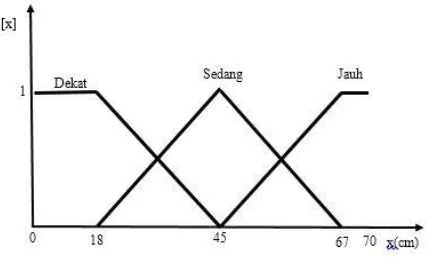
According to Table 2 illustrates that the compilation fuzzy is determined by membership function is dekat, sedang, jauh. The Input membership function graph shown in Fig 9.
Fig. 9 Graph Input Membership Function y = 5.9961e0.0201x
0 15 30 45 60
0 15 30 45 60 75 90 105 120 135
Pix
e
l
Jarak (cm)
Obstacle distance (Cm) Pixel Values
16 50
20 59
25 70
30 80
35 88
40 95
45 101
50 106
55 111
60 115
65 118
4
Based on the membership function as the formulation function as shown in (2) to dekat, (3) for sedang and (4) for jauh.
𝜇 𝑑𝑒𝑘𝑎𝑡[𝑥] = {(45 − 𝑥)/(45 − 18) 𝑢𝑛𝑡𝑢𝑘 18 < 𝑥 < 45 1 𝑢𝑛𝑡𝑢𝑘 𝑥 ≤ 18
In this study robot avoider has three parts of the sensor that is part of the front, left and right with three sets fuzzy.That is the rule base of these systems have a 27 basis rule. Table 3 shows the rule base on fuzzy logic systems are designed.
TABLE 3. BASIS OF FUZZY LOGIC RULES DESIGNED
Distance Dekat (dt3) Sedang (sd3) Jauh (jh3)
Dekat dekat C L C L C L
L: Lambat(slow), C: Cepat(fast), S: Sedang(middle)
Mechanism Rules
After designing the next rule base is to use regulatory
mechanisms to generate fuzzy output. Mechanism rules using
Sugeno method for the calculation process are suitable for use as
a robot control to avoid the obstacle. Functional implications
were used that operation Max-Min on the function of a specific membership and generate fuzzy output as shown in (5).
µ (y) = max [min [ µA1(input (i)), µA2(input (j)), µA1(input (k)),…. ]] (5) The set of fuzzy output in the form of regulatory mechanisms output singleton with a range 0 to 255 are mapped into 3 linguistic variables. The third variable is slow with a value singleton of 100, while the singleton 185 and fast with singleton 255. The graphical output of used in the operation Max-Min is shown in Fig 10
Fig. 10 Graph output membership function
Defuzzification
To determine the defuzzification process steps accomplished
by using the equation Weight Averagefor the method of taking
the average value using a weighted form of membership degree. Where equation for defuzzification shown in (6).
𝑃𝑊𝑀 = ∑ 𝜇(𝑦) 𝑦∑ 𝜇(𝑦) (6)
Where the PWM isoutput value, y is the value of crispand μ(y)
is the degree of membership of a values crisp y.
4. RESULTS
Tests were conducted in this study consists of several stages.
A. Testing Laser Camera
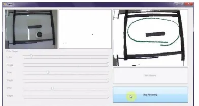
Laser test is intended to determine the camera's performance in detecting obstacle with various angles obtained. Fig 11 shows the output of the camera to capture an object as an obstacle. From the test results corner, amounting to 18 in increments of movement every 100 starting from the point 00 up to 1800 at different distances. The sensor is able to know the whereabouts of a hindrance given black color.
Fig. 11 Output Results Capture Camera Against Objects As obstacle
The next test is done with a single point of laser range finders on each sensor area to ensure that the obstacle can be detected by the system that has been created. There are several tests performed on each of the sensors is in the sensor area left as seen in Fig 12.
Fig. 12 Experiment Camera Sensor Detects Obstacles in the Left
Fact distance between the robot with the obstacle on the left sensoris 39 cmand a pixelis read sensor is 94 pixels. To find the
Based on the results of testing that has been done shows that the value of radians on coordinates (x, y) is 0523 x is 81 and y is
47. So the point coordinates (x, y) from the value of thepixel94
In the second experiment performed obstacle detection stage in the middle sensor as seen in Fig 13.
Fig. 13 Experiment Camera Sensor Detects Obstacles In the Middle
In the middle sensor testing, the actual distance between the
robot obstacleis 36 cmand a pixel that is 90unreadable. Pixels
Experiment Camera Image Sensor Detects Obstacles In The Right can be seen in Fig 14.
Fig 14 Experiment Camera Detects Obstacles In The Right Sensor
Test data on the right sensor for the actual distance between
the robot obstaclesis 34 cmand pixelread sensor is 87 pixels. To
prove that the 87 pixels are 34 centimeters, then do the calculation using the equation y = 5.9961e0.0201xby y is the value
of the distance in centimeters and x is the distance in pixels. The results obtained showed that the distance (y) worth 34.45 cm. Based on manual calculations show that the results obtained resemble the results of tests performed.
In the fourth experiment performed on all parts of the obstruction detection sensors as shown in Fig 15.
Fig. 15 Experiment Camera Detects Obstacles In each area sensor
Based on Figure 15 it can be seen that the hitch on each sensor area can be detected either by a system that has been created. This experiment proves that the designed system is able to run well.
B. Robot Navigation System Testing
Testing was conducted to determine the performance of
fuzzy algorithm’s for navigation systems used on the robot.
Testing is done by running the robot on track or corridor with 1 round. The shape of the corridor to be used can be seen in Fig 16.
Fig. 16The arena testing for testing robot motion
Fig 16 shows that the state in which the location of the robot
avoider move. Arena installed a black object in which the
distance between the object with other objects as far as 60 cm. So the object can be identified, then the object is given dark
color. Backgroundof the arena fitted with white or bright colors
to produce contrast differences.
To get the robot ideal trail then performed manual measurements and distance between obstacles. Figure 17 shows the robot's path is ideal in corridors 1 lap.
Fig. 17Form of the Ideal line robot movement
Fig 17 is used as a reference for comparison of test results. The results that resemble the shape of the ideal track test results that most good. Test results of the first round of the corridor can be seen in Fig 18 and Fig 19.
Fig. 18 Trajectory Experiment 1 Running Track 1 Round 60 cm
60 cm
60 cm
60 cm
6
Fig. 19 Trajectory Experiment 2 Tracks 1 Round Track
To find out the test results was more similar to the ideal paths robot than used method of calculating the Euclidean distance, comparing the results of the test image with the image of the ideal robot's path. To calculate the distance Euclidian then used equation (9).
𝑗(𝑣1, 𝑣2) = √∑ (𝑣𝑁𝑘=1 1(𝑘) − 𝑣2(𝑘))2 (9)
Where v1 and v2 is two vectors (pixels) that the distance will be
calculated and N denotes the length of vector (pixel). To compute the Euclidian distance on the results of experiments with the
robot ideal path taken by trajectoryof each. The results showed
that the better or similar trajectory generated, then the distance is getting smaller. Fig 20 is the result of the comparison in the test 1.
Fig. 20.The comparison Trajectory of Test 1
Trajectory Comparison in Fig 20 shows that the results of Euclidian worth 75.796. Fig 21 is the result of the comparison Trackjectory on testing 2.
Fig. 21.The comparison Trajectory Experiment 2 in this
study
Results Euclidian based on Fig 21 is 75.796. Having obtained
the value of each Euclidian then so do the maximum value search
Euclidian distance. Fig 22 shows the maximum value outcome
Euclidian distance.
Fig 22.Results of Euclidian distance maximum value
Based on the maximum value Euclidian distance can be
searched percentage yield comparisons to find out the results trajectorythat more closely tracks ideal robot. The percentage value can be obtained using the equation "10"
p = 100% - ((a/b) x100%) (10)
Where p is the percentage of similarity, a is the Euclidean
distance, b is the maximum Euclidian distance
By use of the (10) percentage trajectory similarity can be calculated so that in one experiment obtained a percentage of 72.65% and for the calculation of the percentage of similarity in trial 2 was obtained 73.65%. Based on the percentage of the tests that have been done show that the similarity track actual robot approaching the ideal path.
5. CONCLUSION
Based on test results and observations on the robot avoider system uses system an omnidirectional vision can be concluded that the system can help reduce the amount of sensor on the robot. And the percentage of the system's success in detecting trajectory ideal of 73.15%.
REFERENCES
[1] Menegatti, E., Pretto, A., Scarpa, A., & Pagello, E.
Omnidirectional scan matching vision for robot localization in
dynamic environments.Robotics, IEEE Transactionson, 22(3),
(2006) 523-535.
[2] Warasih, H., Lasti. 2007. Design of Mobile Robot with Camera Sensor Using Fuzzy Control System. University of Indonesia. Jakarta.
[3] Agus, Delta Abadi. The ultrasonic sensors as a navigation tool robot in robot-based microcontroller ATMega8535 fireextinguisher. Dipenegoro University, Semarang.
[4] Putranto, Benedictus YB et al, 2010. Color Image Segmentation with HSV Color Detection to Detect Objects. Journal of Technology, Volume 6 number 2.
[5] Fatmi, Anis, Amur Al Yahmadi, LazharKhriji and NouriMasmoudi. 2006. A Fuzzy Logic Based Navigation of a MobileRobot.Proceedings of World Academy of Science, Engineering and Technology.
[6] Purnamasari ita. 2014 Robot avoider Design and Analysis System Using Omnidirectional Vision with Digital Image. Sriwijaya University, Palembang.
[7] Jatra Muhammad, Isnanto Rizal R., Imam Santoso. Identification of Iris Eye Method Using Principal Component Analysis and Calculation of Euclidean distance. Diponegoro University, Semarang (2011)
[8] Andriani, Deni Ria. The ability Colonization Various Formula