Indar Sugiarto
1, Lauw Lim Un Tung
2, Mohammad Ismail Rahman
31,2,3
Department of Electrical Engineering - Petra Christian University Jl. Siwalankerto 121-131, Surabaya, Indonesia – 60236
Tel: +62-31-2983112, Fax: +62-31-8436418
Email: [email protected], [email protected], [email protected]
ABSTRACT
This paper describes an application of fuzzy logic to solve the problem of an autonomous mobile robot in tracking the path within a maze. The robot equipped with ultrasonic transceivers to measure the distance between robot and the wall. The information of distance then will be processed using fuzzy-based algorithm and implemented in two chips FPGA. The FPGA has responsibility to formulize the rule of the fuzzy and generate the PWM signals for robot’s motors as the result of fuzzy inference. Implementing all necessary fuzzy logic algorithms will require many FPGA resources. Therefore, we use two FPGAs: XC4010E and XC4005XL. The first one for the fuzzification and rule base evaluation, and it consumes 98% of its resources (CLBs). The second one for defuzzification and PWM output generation, which utilizes 78% of all its CLBs. By implementing fuzzy logic using FPGA, the robot achieves relatively safe tracking the path in real-time sense.
Keywords: Fuzzy Logic, Autonomous Mobile Robot, FPGA, Ultrasonic Distance Measurement
ABSTRAK
Dalam paper ini dijelaskan aplikasi logika fuzzy pada robot bergerak untuk mencari jalan keluar dalam sebuah labirin. Robot dilengkapi dengan pemancar dan penerima ultrasonic sebagai pengukur jarak antara robot dengan dinding labirin. Informasi berupa jarak tersebut kemudian diproses menggunakan algoritma fuzzy yang diimplementasikan dalam dua buah FPGA. FPGA bertanggungjawab dalam memformulasikan aturan dari logika fuzzy yang digunakan dan membangkitkan sinyal-sinyal PWM untuk mengendalikan motor robot sebagai hasil dari proses inferensi. Untuk mengimplementasikan semua fungsi-fungsi logika fuzzy, dibutuhkan banyak sekali sumber daya FPGA. Karenanya kami menggunakan dua buah FPGA: XC4010E dan XC4005XL. Komponen FPGA yang pertama, yakni XC4010E, digunakan secara khusus untuk proses fuzzification dan menggunakan 98% dari sumber daya FPGA yang berupa CLB. Komponen FPGA yang kedua, yakni XC4005XL, digunakan untuk proses defuzzification serta pembangkitan sinyal PWM, dan menggunakan 78% dari total CLB yang tersedia. Dengan mengimplementasikan logika fuzzy menggunakan FPGA, robot dapat menelusuri jalur labirin secara real-time dengan lebih aman.
Kata kunci: Fuzzy Logic, Robot Bergerak Otomatis, FPGA, Pengukur Jarak Ultrasonic
INTRODUCTION
Control system using fuzzy logic for mobile robot gained its popularity since initial development in early 1990. Until now, this relatively new application of intelligent robot has become intensively pursued in research. A mobile robot is an autonomous robot with capability to move itself freely according to its predetermined program. This ability to move can be classified into two main categories: robot with predetermined/planned trajectory, and robot with ‘instinct’ to avoid obstacles by observing its environ-ment. Therefore, there are two major approaches taken to intelligent robot design [1]. One emphasizes stored internal state and the other depends on local sensor information.
Note: Discussion of this paper must be submitted before December 1st, 2008. The proper discussion will be published in Electrical Engineering Journal volume 9, number 1, March 2009.
Fuzzy methodologies is used for motion planning in unknown path using fuzzy rules and for coordinating different types of reactive behaviors. Fuzzy logic is used here because we try to simulate human-like approach rather than exact-mathematical formulation for mobile robot control system [3]. Using this fuzzy approach, the robot can steer left, right, or straight with its speed can be controlled automatically. The overall architecture of the approach is schematically
illustrated in Figure 1.
Figure 1. The architecture of the mobile robot. It is equipped with a learning capability through its
environment sensing.
The remainder of this paper is organized as follows. In Section 2, we introduce our proposed distance measurement with ultrasonic sensors for a mobile robot. In Section 3, we review the necessary fuzzy terminology. In Section 4, we examine the implemented fuzzy approach with FPGA and the section 5 is final comments and our plans for future work.
APPROACH AND METHOD Mobile Robot with Ultrasonic Sensors
Ultrasonic transducers can be used as distance measurement devices, which can give relatively high accuracy, especially for short distance measurement requirement [4]. Figure 2 shows the configuration of sensors within the robot.
motors front sensors
left sensors
right sensors
Figure 2. The configuration of sensors within robot body.
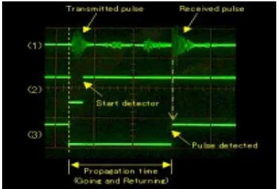
An ultrasonic distance measurement system was designed using microcontroller 89C51. This micro-controller was equipped with ultrasonic transceiver and a counter circuit. The transceiver sensors worked
with sound wave, which is modulated and propagated in the frequency of 40 kHz. The designed circuit can be used to detect distances between 3 cm and 1 m. To measure longer or shorter distances, the sensors circuit must be modified. Here is the block diagram of the distance measurement system.
Microcontroller 89C51 modulator
circuit amplifier
circuit amplifier
circuit
comparator circuit
counter circuit
Figure 3. Transceiver circuit for distance measure-ment.
The system works as follows. Microcontroller 89C51 will generate start command for both modulator circuit and counter circuit. Modulator circuit will start generate modulated ultrasonic wave and transmit it, meanwhile the counter start to count. Immediately after the comparator circuit receives the amplified ultrasonic wave, which is received from the environment as the reflected wave, the counter circuit will stop. The amount of bits counted by the counter is equivalent with twice of distance measured. The 89C51 then calculated the correct distance from the counter and sent the result to the FPGA for further calculation.
Figure 4. Model of transceiver’s signals.
Two motors in the bottom of robot body receive the amplified signal from the FPGA. These signals are PWM signal that are correspond to the direction and speed of the motors.
Fuzzy Logic Approach
R: IF <fuzzy criteria> THEN <fuzzy conclusion>
where <fuzzy criteria> and <fuzzy conclusion> either are atomic or compound fuzzy propositions. Such a rule can be seen as a causal relation between measurements and control values of the process. A rule base contains all the fuzzy rules that are needed for an inference mechanism to provide conclusions (control signals) from input signals.
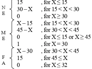
The process of fuzzification includes three 6-bit inputs from ultrasonic sensor counter left, right, and the front, which represent the distance between the robot and the wall. The chosen membership functions are trapezoid and triangles with labels: far (fa), medium (me), and near (ne). The following figures demonstrate the membership function for the three inputs:
Figure 5. Membership functions for left and right inputs.
Figure 6. Membership function for the front side input.
One of the limitations in our design is the capacity of the FPGA’s logic resources. For that reason, we use singleton membership function for the output. Figure 7 shows the membership function for the output of the fuzzy logic system.
Figure 7. Membership functions for the output of the fuzzy logic system.
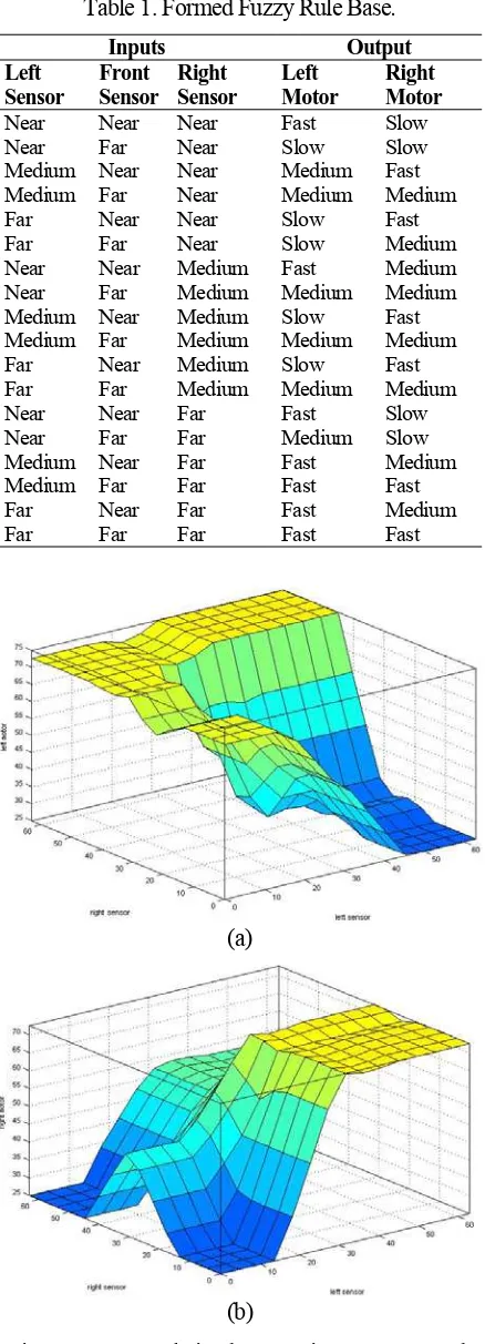
The next process is Rule Evaluation to relate the fuzzy input and output. The following is the fuzzy rule base table. This rule will yield fuzzy relation as shown in figure 8.
Table 1. Formed Fuzzy Rule Base.
Inputs Output Left
Sensor
Front Sensor
Right Sensor
Left Motor
Right Motor Near Near Near Fast Slow Near Far Near Slow Slow Medium Near Near Medium Fast Medium Far Near Medium Medium Far Near Near Slow Fast Far Far Near Slow Medium Near Near Medium Fast Medium Near Far Medium Medium Medium Medium Near Medium Slow Fast Medium Far Medium Medium Medium Far Near Medium Slow Fast Far Far Medium Medium Medium Near Near Far Fast Slow Near Far Far Medium Slow Medium Near Far Fast Medium Medium Far Far Fast Fast
Far Near Far Fast Medium Far Far Far Fast Fast
(a)
(b)
The aggregation used in the proposed method is the maximum aggregation. It means that the maximum value is taken from rules where the rule with the same label has the maximum values. The inference method that is adopted by our system uses the method of Center of Gravity (COG)[6,11]:
( )
FPGA (Field Programmable Gate Array) is a programmable device, which can be configured and programmed using HDL (Hardware Description Language) method. For our research, we use two FPGA from Xilinx: XC4010E and XC4005XL. Prior to the implementation of the system, we assumed that the XC4010E solely will not enough in providing all necessary resources. Later in the implementation step, our assumption was proven correct. The XC4010E is used mainly for fuzzification and rule base evaluation. The XC4005XL is used for defuzzification and PWM output generation.
Basically, both XC4010E and XC4005XL have the same internal structure. Both are SRAM type FPGA, means that the content of the FPGA will loss when the electric power of the device is disconnected from the source. XC4000 Series devices are implemented with a regular, flexible, programmable architecture of Configurable Logic Blocks (CLBs), interconnected by a powerful hierarchy of versatile routing re-sources, and surrounded by a perimeter of pro-grammable Input/Output Blocks (IOBs). CLBs provide the functional elements for constructing the user’s logic, while IOBs provide the interface between the package pins and internal signal lines. The following figure shows the general architecture for the XC4000 family of Xilinx FPGA.
Figure 9. The basic building blocks for XILINX XC4000 FPGAs.
To program the FPGA, we used VHDL (Very High Speed Integrated Circuit Hardware Description Language) for modeling and synthesis. After the VHDL program was written, it will go through several steps of synthesize and implementation. We used software Xilinx Foundation 2.1i for synthesizing and implementation. The result of the implementation step is a bitstream data that need to be downloaded into the FPGA. Alternatively, this bitstream may be stored in an external EPROM for standalone application. Figure 10 shows how the interconnection between both FPGAs with the rest of the system.
Figure 10. Block diagram of the system.
In our research, we use degree of membership function of up to 15 (see figures 5 and 6) to simplify the calculation by the FPGA. The distance is limited to 63 cm in order to fit the variable bits. From the figures 5 and 6, it must be determined 10 equations for the curves using the following line equation:
Y – Y1 = m (X – X1) (2)
For example, for segment line number 2 in figure 5 we will get:
m = -1, so : Y – 15 = -1 (X – 15) or : Y = 30 – X , for 15 < X < 30
Using the method described above, we got the membership function equation for left and right inputs as follows:
15
The following script shows how these equations must be written in term of VHDL for FPGA programming, for example is the label NE:
ne_l: process (rst, clk, x)
“011110”) then ne1 <= “000000”;
end if; end if;
end process;
The following table shows the simulation result using software Xilinx Foundation 2.1i.
Table 2. Experiment result from the simulation.
Inputs (cm) Simulation Result Manual
Calculation Error (%)
medium, and slow to output left
• F2, M2, S2: maximum aggregation for fast,
medium, and slow to output right
• Kl, Kr : simulation result of COG calculation
for output left and right
• KlP, KrP : manual calculation of COG for output
left and right
• KlE, KrE : error calculation of COG for motor left
and right
After verifying that the software design is
correct and it was simulated successfully (using
both functional and timing simulation), we
implement the design on the targeted FPGAs.
The following table shows the implementation
result from the experiment.
Table 3. The experiment result for direction of robot movement.
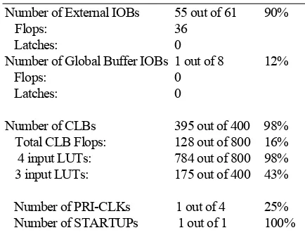
It can be seen from table 3 that the implementation of the fuzzy control shows satisfactory result. However, it should be noted that in our system we did not provide any mechanism for stopping the mobile robot yet. The main goal of this research is to explore the performance of fuzzy logic that is implemented on FPGAs to control movement of a mobile robot. Therefore, the success parameters of this research rely on FPGA implementation information provided by the synthesizer. Xilinx Foundation 2.1i reported the following information as the result of implemen-tation step.
Table 3. Implementation report for FPGA XC4010E
Number of External IOBs 55 out of 61 90%
The Maximum Pin Delay is: 35.883 ns
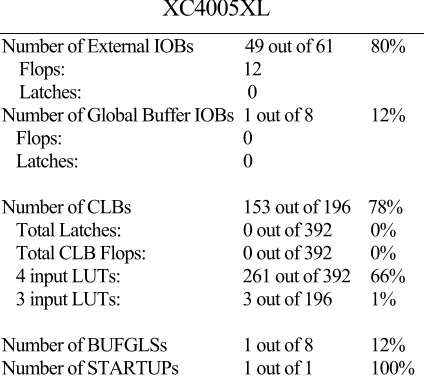
Table 4.
Implementationreport for FPGA
The Maximum Pin Delay is: 11.402 ns
The Average Connection Delay on the 10 Worst Nets is: 9.283 ns
It is shown above that, fuzzification and rule evaluation processes take time longer (twice) than defuzzification and PWM signals generation. Most of arithmetic procedures were carried on the first FPGA. The first FPGA also prone to critical time delay which is undesired for real time application. Fortunately, the frequency of PWM is very small so that those delays will not cause serious pulse defects.
CONCLUSION
This paper deals with the real-time navigation of a mobile robot in a maze using fuzzy approach to endow the robot with the human being ability to reason and avoid collision. The robot equipped with only rudimentary sensing capabilities using ultra-sonic transceiver. In forming fuzzy rules, testing and experimental studies were utilized. A collision avoidance algorithm has been proposed in fuzzy logic term with partitioning the distances into three membership functions and yielding three singleton membership functions at its output. This algorithm has been validated in several models of maze with right angles without crossing section and has proven to give the robot the means of relatively safe in tracking the path. Implementation of fuzzy control using FPGA gives us attractive benefit in the way such easily configure the hardware to gain real-time performance. In contrary, the disadvantage emerges as the result of rounding the calculation result in term of binary digit. Furthermore, due to limited resources in the targeted FPGAs, we have to use two FPGAs in
our design. We employed low logic resources FPGA that in turn gave us several limitations as described in the section above. The first FPGA is dedicated for the fuzzification and rule base evaluation, and it consumes 98% of its resources (CLBs). The second FPGA is designed for defuzzification and PWM output generation, which utilizes 78% of all its CLBs. Future works may be focused on neurofuzzy mechanisms in order to generate fuzzy logic rules automatically [8,9,10]. In addition, it should be worthwhile to use high density FPGA in order to simplify the hardware and reduce complexity error due to misalignment of bits in arithmetic processes.
REFERENCES
[1] L. H. Tsoukalas, E. N. Houstis, and G. V. Jones, “Neurofuzzy Motion Planners for Intelligent
Robots”, Journal of Intelligent and Robotic
Systems 19: 339–356, 1997.
[2] Kemal POLAT, Seral ŞAHAN, Salih GÜNEŞ,
“Finding Direction of a Mobile Robot Using Microcontroller Based Ultrasonic Distance Measuring Device And Fuzzy Logic”, IJCI Proceedings of International Conference on Signal Processing, ISSN 1304-2386, Volume:1, Number:2, September 2003.
[3] C. Fayad and P. Webb, “Optimized Fuzzy Logic Based on Algorithm for a Mobile Robot Collision Avoidance in an Unknown
Environment”, 7th European Congress on
Intelligent Techniques & Soft Computing, Aachen, Germany, September 13-16, 1999.
[4] Irving, Robert, Sound and Ultrasonics, Knopf,
New York, 1959.
[5] F. Martin McNeill, Ellen Thro, Fuzzy Logic: A Practical Approach, Academic Press Inc., 1994. [6] Bart Kosko, Neural Networks and Fuzzy
Systems: A Dynamical Systems Approach to Machine Intelligence, Prentice-Hall International, Inc., 1992.
[7] Patrik Eklund, Lena Kallin, Tony Riissanen, Fuzzy Systems, Lecturer Notes, Department of Computing Science - Umeå University, Sweden, 2000.
[8] Felix Pasila, Indar Sugiarto, “Mamdani Model for Automatic Rule Generation of A MISO
System”, Proceeding of Seminar On Soft
Computing, Intelligent Systems, And Information Technology, Petra Christian University, Indonesia, 2005.
[10] Hossein Salehfar, Nagy Bengiamin, Jun Huang, “A Systematic Approach To Linguistic Fuzzy Modeling Based On Input-Output Data”, Proceedings of the 2000 Winter Simulation Conference: 2000.
[11] Hao Ying, Fuzzy Control and Modeling –