For your convenience Apress has placed some of the front
matter material after the index. Please use the Bookmarks
v
Chapter 1: LEGO, Arduino, and The Ultimate Machine
■
...
1
Chapter 2: Using Sensors with the Android
■
...
27
Chapter 3: Twitter Pet
■
...
.65
Chapter 4: RFID and the Crystal Ball
■
...
89
Chapter 5: Animating the TARDIS
■
...
111
xvii
For 80 years, The LEGO Group has produced building toys for children to enjoy. As technology has advanced, they have introduced some interactive components that were limited in different ways.
The Arduino is an open source microcontroller that allows interaction with all different forms of electronic devices and sensors. It allows for many creative projects that can be controlled by a device that is a small, low-powered computer.
By combining these two flexible systems, myriad projects can be built that can do almost anything—the only limit is your imagination.
1
LEGO, Arduino, and The Ultimate
Machine
For years LEGO has produced their own computer based system known as Mindstorms. It gave a computer brain to the plastic LEGO bricks that had been around for decades. While Mindstorms has advanced in the 15 years since it was introduced, it was still limited based on the size of the LEGO Intelligent Brick and the available sensors and motors. An alternative to using the LEGO Mindstorms is the Arduino microprocessor, a small computer that can make use of any electrical components with some programming.
Introducing the Arduino
An Arduino (as seen in Figure 1-1) is an open source microcontroller that allows for programming and interaction; it is programmed in C/C++ with an Arduino library to allow it to access the hardware. This allows for more flexible programmability and the ability to use any electronics that can interface with the Arduino. Because the Arduino is open source, the plans for the circuits are available online for free to anyone who wants to use and create their own based on the schematics, as long as they share what they create. This allows for a lot of customizability in projects, since people have built Arduinos of different sizes, shapes, and power levels to control their projects.
CHAPTER 1 ■ LEGO, ARDUINO, AND THE ULTIMATE MACHINE
2
The main advantages of using the Arduino over LEGO’s own motor systems are the open source base, the expandability, and the sizes. With LEGO’s system, the user is locked into the pieces LEGO created. This can be a hindrance with smaller projects where the Mindstorms NXT Intelligent Brick can be too large to easily incorporate or hide the intelligence behind the project. With the smaller Arduino circuit board, less clearance is required to hold the circuit board, which means more flexibility in the design of the project. A comparison of the Arduino and the LEGO NXT brick can be seen in Figure 1-2.
Figure 1-2. The Arduino and the LEGO Mindstorms NXT Intelligent Brick
3
Your First Arduino Program
Most commonly, when someone tries out a new computer language, they make the words “Hello World” appear on the screen. The Arduino version of this is to make a light-emitting diode (LED) blink. By plugging the LED into two of the ports on the Arduino and writing a simple program, the Arduino can turn the light on and off.
The first step is to put the LED into the Arduino. LEDs are specific to the way they are used. The LED needs to be plugged in so that the longer end goes into a numbered pin and the shorter pin into the ground pin, or the LED will not light up. Figure 1-4 shows the longer side in the socket labeled 13 and the shorter side in the ground.
CHAPTER 1 ■ LEGO, ARDUINO, AND THE ULTIMATE MACHINE
4
Once the LED is firmly placed in the Arduino, the next step is to connect it to a computer via USB cable. The computer must have the Arduino software installed in order to program the Arduino. The software can be downloaded for free at arduino.cc in the download section for your computer operating system of choice. Once it is downloaded and installed, open the Arduino software. The following program can be found in File ➤ Examples ➤
01.Basics ➤ Blink or it can be entered by hand, as shown in Listing 1-1.
Listing 1-1. Basic Blink Program
/* Blink
Turns on an LED on for one second, then off for one second, repeatedly.
This example code is in the public domain. */
// Pin 13 has an LED connected on most Arduino boards. // give it a name:
int led = 13;
// the setup routine runs once when you press reset: void setup() {
// initialize the digital pin as an output. pinMode(led, OUTPUT);
}
5
// the loop routine runs over and over again forever:void loop() {
digitalWrite(led, HIGH); // turn the LED on (HIGH is the voltage level) delay(1000); // wait for a second
digitalWrite(led, LOW); // turn the LED off by making the voltage LOW delay(1000); // wait for a second
}
The code in Listing 1-1 is the most basic program for an Arduino. It is read by the Arduino from the top down. The first thing in the program is a global variable definition for the pin that has the LED. A global variable is defined outside the setup() and loop() functions and can be accessed from anywhere in the program. The line int led=13;
defines the global variable named led to be an integer with the value of 13. Whenever the word led is used, the program will interpret it as the number 13. Since the variable is defined before the words void setup(); it is what is referred to as a global variable, which means any part of the program can access and make changes to it. If the variable had been defined in the setup or loop sections (as defined below), it would only be a local variable that could only be accessed by that section of code. It is worth noting that anything between the symbols /* and */ or on a line after // are comments and will be ignored by the computer when it reads the program.
// the setup routine runs once when you press reset: void setup() {
// initialize the digital pin as an output. pinMode(led, OUTPUT);
}
Anything between the braces after setup() will be executed when the program first runs. Anything in there will be run only once and never be looked at again. In this case, it using pinMode to tell the Arduino that it will be using pin 13, where you defined led, to be used to send a signal out. It is notable that the pins can be used for either input or output, but must be defined to do so.
// the loop routine runs over and over again forever: void loop() {
digitalWrite(led, HIGH); // turn the LED on (HIGH is the voltage level) delay(1000); // wait for a second
digitalWrite(led, LOW); // turn the LED off by making the voltage LOW delay(1000); // wait for a second
}
Once the setup runs, it then executes whatever is between the braces after loop(). The difference is that once the section in the loop() starts, it will start that code over again once it reaches the end. Pin 13 on the Arduino has only two states, off and on. The digitalWrite function tells the light to turn on and off based on whether it is told to be HIGH or LOW. Putting a delay between the digitalWrite statements provides the ability to see the light turn on and off rather than just a strobe effect. The delay statement will wait as long as the number in the parentheses is, in thousandths of a second.
CHAPTER 1 ■ LEGO, ARDUINO, AND THE ULTIMATE MACHINE
6
There is often considered a do-it-yourself (DIY) aspect to open source hardware, and sometimes manufactures will sell products like shields with some assembly required. With some basic soldering knowledge, they are not too complex to put together. The instructions on how to assemble it can be found at www.ladyada.net/make/mshield/solder.html. Figure 1-6 shows the motor shield assembled.
Programming the Ultimate Machine
The Ultimate Machine, also known as The Useless Machine, is considered the most efficient machine ever made. Its only task is to turn itself off when it is turned on. The original Ultimate Machine was created by Claude Shannon when he was working at Bell Labs in 1952. The following sections explain the steps involved.
Assembling the Arduino and Motor
In order to build the Useless Machine, a motor is required. To drive the motor, a motor shield will need to be placed on top of the Arduino. While there are a few different shields that would allow for a motor to connect to the Arduino, we will be using the Adafruit Industries motor shield because we can use it to drive the different kinds of motors you will be using in different projects in this book. Figure 1-5 shows the motor shield from Adafruit Industries in its unassembled form.
7
Once the motor shield is soldered together, it snaps in easily on top of the Arduino. Press them together firmly but do not push too hard. Once they are together, it’s time to add the motor. The Adafruit motor shield supports DC motors, servo motors, and stepper motors. For this project, you’ll be using a servo motor. The motor’s wires plug in on the top left on the three pronged plugs (see Figure 1-7).
Figure 1-6. The assembled motor shield
CHAPTER 1 ■LEGO, ARDUINO, AND THE ULTIMATE MACHINE
8
In the Blink example, you power the Arduino with the USB cable to the computer. Since this project will eventually be independent of the computer, a battery pack or wall adapter will be required to power the project. If the wall adapter is used, it plugs directly into the Arduino, and the LEGO casing will require a hole the width of one LEGO stud. Some motors will require a second power source due to the power consumption of the motors, but for this project, the single power source will be enough for the Arduino and servo motor.
With the Arduino and motor shield set up, there is one last piece of hardware to connect before programming your project. The Ultimate Machine moves into action when a person flips a switch to turn the machine on. Since the machine needs to be switched on, you need to add a switch. You will take a switch (the one in Figure 1-8 is from Radio Shack), solder wires to it, and plug it into one of the digital ports on top of the motor shield so the machine will know when to activate. Since you are using the shield rather than the Arduino itself, the wires will need to be soldered in place to make a secure connection. One end will be soldered into the numbered pin, the other end will be soldered into one of the ground ports, as shown in Figure 1-9.
9
Programming the Arduino
Once the hardware is completed, it is time to build the software. The program to run the motor is has a similar layout to the program you wrote for the Blink program, but is a little more advanced. The first thing you need to do is include the library for the motor shield. The library includes code that has already been written to drive the motor shield, so you don’t have to start from scratch to address the hardware yourself. To install the library, go to
www.ladyada.net/make/mshield/use.html and follow the instructions to download and install the motor shield library. Once it is installed and the Arduino software is restarted, copy the code in Listing 1-2.
Listing 1-2. The Ultimate Machine Code
#include <Servo.h>
// DC hobby servo Servo servo1;
// Switch connected to digital pin 2 int SwitchPin = 2; // and enables pullup resistor pinMode(SwitchPin, INPUT_PULLUP); }
CHAPTER 1 ■ LEGO, ARDUINO, AND THE ULTIMATE MACHINE
// test if switch has been triggered if (val == LOW) {
Again, the code is broken into three parts. The first part contains the global variable definitions. Here, you set variables that you want accessible throughout the code. The two include statements at the top of the code include the libraries to interact with the motor. The #include <AFMotor.h> tells the Arduino code that you are going to be using the motor library and the #include <Servo.h> loads the necessary code to use a servo motor. After including them both, you can initialize the servo motor with Servo servo1, which defines the motor and gives it the name servo, which is how you will refer to it as in the rest of the code. Int SwitchPin = 2 sets a number value to SwitchPin, which will be the pin that one end of the switch was soldered into.
In the setup() section, you set up the motor and switch so that you can use them in the loop().
Servo1.attach(9) turns on the servo and tells the code that the servo can be accessed through digital pin 9.
pinMode(SwitchPin, INPUT_PULLUP) sets the pin to an input mode to receive digital signals from an external device, in this case a switch. It will be on the port you previously defined in the int statement, so when the switch is active on that port, the code will be able to react.
The third and final part of the code is the loop(). The first thing you need to do is check the status of the switch, so int val = digitalRead(SwitchPin) will put a value in the val variable based on whether the switch is open or closed. The if statement checks the status of the val variable, and if it is LOW, it executes the code within the braces of the if statement. The code will tell the servo motor to move forward 115 degrees with the servo1.write(115)
command, then waits 250 milliseconds in the delay(250)command before returning back into the box with
servo1.write(0). Once the motor is reset to its initial position, it continues the loop and waits for the switch to be flipped again to turn itself off again.
A typical hobby servo motor can only move 180 degrees, but your motor does not need to move that far to trigger the switch. When building the project, if the motor doesn’t move far enough or if it moves too far, adjusting the 115 in the servo1.write() command will adjust how far the motor moves.
Building the Ultimate Machine
11
Now that you have decided how you will build the base, you need to figure out the dimensions of the box.
Selecting the Dimensions
The box needs to be at least as wide as the Arduino, and you need to consider how you will fit in the other parts of your build. The Arduino will sit beneath the switch and motor, so you need to figure out the layout of the parts in order to know how big the box needs to be. For the servo to line up to the switch properly the box needs to be approximately 6.5" x 4" or 20 x 12 LEGO studs. In Figures 1-12 to 1-14, you can see how laying out the plates and then crossing over the seams in opposite directions between layers provides a solid foundation that is one brick high.
The complete parts list for this project can be found in the appendix.
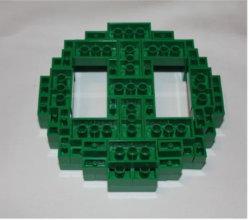
To give the box a solid foundation, you are going to build the bottom of the box. If you laid out bricks, it wouldn’t be very strong and you would need to do a couple layers to give it the tensile strength required to pick up the box and not have the bottom fall out. Instead, you will use plates. When stacking LEGO plates, three plates are the same height as a single LEGO brick, so they can be alternated in your building to cover the seams and still keep the height down by using three plates instead of three bricks. In Figure 1-11, you can see how three plates stack up to be the same height as one brick.
Figure 1-10. On the left are LEGO bricks stacked one atop the other, while on the right are bricks in a staggered formation. Notice how the bricks cover the seams above and below them, holding the bricks together
CHAPTER 1 ■ LEGO, ARDUINO, AND THE ULTIMATE MACHINE
12
Figure 1-12. LEGO plates are laid out to create the base of the box
13
Building the Brick Walls
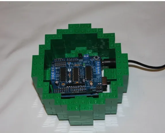
Now you can start laying down your bricks. For the first layer, rather than just putting a ring around the edge, you are also bisecting the base to make two rectangles (see Figure 1-15). One rectangle is big enough to hold the Arduino and the motor shield, so that when the box is moved around, the Arduino will not shift. The Arduino should fit in the larger box on the base with only a little bit of extra room. In order to fit a cord to power the Arduino, you should leave a one-brick-width hole in the side of the box. Alternatively, you could attach a 9-volt battery box to the project. If you want to use a battery, you can make a box to hold it as well.
CHAPTER 1 ■ LEGO, ARDUINO, AND THE ULTIMATE MACHINE
14
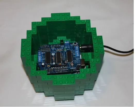
Now you can begin to build up the box over the base you just made. As you lay down the bricks, notice how the second layer covers the seams of the first layer. This will make the box strong enough to support the layers above it and will not break when just picking it up. The next layer, shown in Figure 1-16, will build upon what you have built so far, but cover the seams to strengthen the walls.
Figure 1-16. A layer of bricks is added to begin building up the box
15
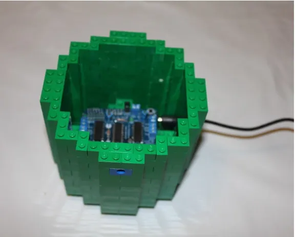
Now add a third layer of bricks to clear the top of the Arduino and motor shield. It’s important to make sure that the height of the box’s walls clears not only the top of the motor shield, but gives enough room on top for the motor’s plug as well to avoid pressure on the shield connection. Again, you should alternate seams to give the box strength to hold the motor and switch (see Figure 1-17).
Figure 1-17. The first three layers of the box, including bricks turned in to create a shelf to hold the motor
Adding The Arduino
CHAPTER 1 ■ LEGO, ARDUINO, AND THE ULTIMATE MACHINE
16
Figure 1-18. The Arduino is easily seated into the section you made for it
Figure 1-19. The small LEGO box to hold the toggle switch with the wires fed through a Technic brick
17
A platform is then added to hold the toggle switch and servo motor. The switch and motor need to be lined up when the machine is turned on. The motor is lined up with LEGO bricks to keep it in place while you build the rest of the box. It will be made more secure as the walls are built higher, which can be seen in Figure 1-20.
Figure 1-20. The servo motor and toggle switch are laid out on top of stacked LEGO plates and lined up using LEGO bricks
Adding LEGO Arms and a Switch
CHAPTER 1 ■LEGO, ARDUINO, AND THE ULTIMATE MACHINE
18
Figure 1-21. A curved Technic beam is wired to the servo motor’s disc
19
Figure 1-23. Four axle joiners and three 2M pins extend the switchCHAPTER 1 ■ LEGO, ARDUINO, AND THE ULTIMATE MACHINE
20
Raising the Walls
With the motor arm and switch extension in place, the walls of the box need to be built higher. The walls should be high enough to cover the switch and motor arm. LEGO bricks extend from the walls to cover the bricks holding the motor in place, and another is extended over the motor itself to keep the motor from rising when the arm activates. If there is too much space between the brick above the motor and the servo, fill the space with LEGO plates for a tighter fit. Also note that there are two 2x2 bricks in the top row. These will hold the lid when it is closed to keep it from falling into the box. See Figure 1-26.
Figure 1-25. The motor arm and switch extension are added
21
Building the Lid
Now that the box is prepared, you need to make the lid. Use Technic beams because the rounded ends will make it easier for the box to open and close. Using two pins between each Technic beam will hold them securely and they will not be able to move. Figures 1-27 and 1-28 show the parts and assembly of the lid.
CHAPTER 1 ■ LEGO, ARDUINO, AND THE ULTIMATE MACHINE
22
Two Technic bricks with holes in the middle will go on the ends with gray pins to hinge the joint. Use the gray pins there because they are frictionless and allow more movement than the black friction pins. Once the lid is added to the box, a layer of bricks is added around the lid. See Figures 1-29 through 1-32.
23
Figure 1-29. Frictionless pins will go into the 1 x 2 Technic bricks, which will in turn be put into the holes in the end of the beams in the lidCHAPTER 1 ■ LEGO, ARDUINO, AND THE ULTIMATE MACHINE
24
Figure 1-31. The Technic bricks are put on top of the walls of the box
25
With the opening lid completed, all that is left is the cover for the switch. Again, you are going to use stacked plates to cover this part of the box, but you can leave open a slit for the switch. The switch needs to be able to move freely back and forth to turn it off and on. The stick’s extension moves easily within a one-stud width and a four-stud length, as seen in Figure 1-33, with the switch shown. It’s important to secure the hinge of the box down, as shown in Figure 1-34, so usage of the Ultimate Machine does not lift the lid off the box.
Figure 1-34. The activated Ultimate Machine
CHAPTER 1 ■ LEGO, ARDUINO, AND THE ULTIMATE MACHINE
26
With the switch covered, you have completed your first project. By flipping the switch towards the lid, the machine will be activated and the motor arm will come to life, only to push the switch away from itself and return to its dormant state until it is activated again.
Summary
27
Using Sensors with the Android
In the last chapter, you made a machine that interacts with itself. A simple response to flipping a switch to turn itself off is a good start, but for more interactive projects, you need to start working with analog sensors that do more than just turn on and off. Sensors allow a machine to monitor the world around it and react accordingly. In this chapter, you will create a project that will be able to react to its surroundings.
When Google introduced their mobile operating system known as Android, they created a mascot to represent it. The little green robot became synonymous with the cell phones and tablets on which the operating system was installed. You are going to create this Android mascot and make him react to his environment. He will be able to “see” what is going on around him and turn to look when things get close within a 180 degree field of view.
A list of the parts in this chapter can be found in the appendix.
The Ultrasound Sensor
There are many different sensors that can be used to send data from the outside world to the Arduino; one such sensor is the ultrasound sensor. An ultrasound sensor sends out a high frequency sound that will bounce off objects and return to the sensor. The time it takes for the sound to go out and bounce back is then calculated to tell the distance of the object. With a simple calculation, it can be converted into a more human relatable value of centimeters or inches. For this Android, you are going to use the PING))) Ultrasonic Distance Sensor by Parallax, Inc., an Arduino-compatible ultrasound sensor.
As seen in Figure 2-1, the PING))) Ultrasonic Distance Sensor has three pins: 5V, GND, and SIG. The 5V and GND pin on the sensor connect to pins on the Arduino, which will allow the circuit to complete and for power to run through the ultrasonic sensor. The SIG or Signal pin can be connected to any of the digital Arduino pins; it’s how the data is moved from the sensor to the Arduino itself.
CHAPTER 2 ■USING SENSORS WITH THE ANDROID
28
To see how the ultrasonic sensor works with the Arduino, you are going to create a basic program to light an LED light using the ultrasonic sensor. If an object is within a range of 6 inches or less, the LED will light up; otherwise the light will be turned off. First, you need to wire up the sensor, LED, and Arduino, but you will use a breadboard to do your prototyping.
On a breadboard, components that are plugged in on the same horizontal line are connected, so the jumper wires next to the pins are connected to the sensor through the breadboard. On the edge of the breadboard are two lines that run the length of the breadboard and they are connected, but they are meant for power and ground so the different components can share power. A single wire is run from the + and – lines to the 5V and ground pins, which will require less lines run from the parts to the Arduino (see Figure 2-2).
Figure 2-2. A diagram of the layout of the Arduino and sensor
29
To connect the breadboard to the Arduino, you need to start by running the power from the Arduino to the breadboard. By running a wire from the + to the 5V pin and another wire from the – to the ground pin, power can be run through the sensor. The signal pin from the sensor is placed in pin 7 and the positive lead from the LED needs to be put in pin 10 on the Arduino. While the placement of the signal and LED pins is arbitrary among the numbered digital pins, these are the pins used in Listing 2-1, which is based on the sample open source code by David A. Mellis and Tom Igoe.
Listing 2-1. PING))) Example Code
// sets the constants for the sensor and led signal pins: const int pingPin = 2;
// establish variables for duration of the ping, // and the distance result in inches:
long duration, inches;
CHAPTER 2 ■ USING SENSORS WITH THE ANDROID
30
// The PING))) is triggered by a HIGH pulse of 2 or more microseconds. // Give a short LOW pulse beforehand to ensure a clean HIGH pulse: pinMode(pingPin, OUTPUT); // pulse whose duration is the time (in microseconds) from the sending // of the ping to the reception of its echo off of an object.
pinMode(pingPin, INPUT);
duration = pulseIn(pingPin, HIGH);
// convert the time into a distance inches = microsecondsToInches(duration);
// send the value in inches to the Serial Monitor Serial.print(inches);
Serial.println(" inches");
// short delay before starting over again delay(100);
}
long microsecondsToInches(long microseconds) {
// According to Parallax's datasheet for the PING))), there are // 73.746 microseconds per inch (i.e. sound travels at 1130 feet per // second). This gives the distance travelled by the ping, outbound // and return, so we divide by 2 to get the distance of the obstacle. // See: http://www.parallax.com/dl/docs/prod/acc/28015-PING-v1.3.pdf
return microseconds / 74 / 2; }
In this code, you start by defining the pingPin as the pin the ultrasonic sensor is plugged in to and led as the pin that the LED is plugged in to (7 and 10, respectively). In the setup() function, you open a connection to the computer with the Serial.begin(9600), so that the Arduino can communicate with the computer when it is plugged in via USB cable. The 9600 defines the speed of the communication between the two; you are going to use it to monitor the values passed back from the sensor. You also define the LED pin as output but you don’t define the sensor in the setup because the pin connected to the ultrasonic sensor will switch between input and output for sending and receiving the ultrasonic pulses.
31
while inches will be for converting those microseconds into distance values. Next, the sensor sends out a brief signal by setting digitalWrite(pingPin, HIGH); then stops it with digitalWrite(pingPin, LOW);. The sensor is then changed to an input sensor and calculates how long between sending and receiving the signal in the line
duration = pulseIn(pingPin, HIGH).
If the Arduino is connected to the computer, then messages are sent to be viewed on the computer from the Arduino. When the program is uploaded and running, click on the Serial Monitor under the Tools menu in the Ardunio software and a white screen will open. The Serial.print() and Serial.println() functions will allow the code to display information in the Serial Monitor window. In the code, Serial.print(inches) prints the value returned from the sensor and Serial.println(" inches") prints the word inches to the screen and the next text will be on the following line. Putting the word in quotes puts the exact word on screen, while no quotes will put a variable value.
To calculate the duration of time between the time the ultrasonic pulse is sent and when it is received and then turn it into a distance that you can relate to, you need to use a custom function. Just like loop() and setup() are functions, you are creating a new function microsecondsToInches(). The word “long” before the function name in the code allows values to be returned by the functions to where they are called, and in this case they are of the datatype long. A long is a 32-bit number, which also allows decimal places, so a number between −2,147,483,648 and 2,147,483,647 can be returned. The long microseconds in the parentheses allows a number to be passed and referred to like a regular variable, but the value of the microseconds variable is passed in the call to the function, in this case duration because it is between the parentheses.
Any processing done within the function is contained within that function. Any change to variables within the function does not impact the rest of the program unless a value is returned. In the function microsecondsToInches(), you are doing some fairly simple mathematics, so you are doing the math and returning the value on the same line.
You could do more complex processing and set the value to a variable, then have the code read return variable to export the answer from the variable rather than directly from the line of code. In your function, you are dividing the number of microseconds it takes sound to travel an inch and dividing by two, since the duration takes into account the time it takes the pulse to travel to and from the object the sound waves are bouncing off of and returning that value to the function call.
By testing the code and looking at the Serial Monitor, you can see that it takes about 1000 milliseconds to go approximately 6 inches, which you can use to trigger the LED. You check if the duration is larger than 1000 with an if statement, and if it is, you set the LED to turn off; otherwise the else statement means the object in front of the ultrasonic sensor is 6 inches or less from the sensor and it will turn on.
Adding Additional Sensors
CHAPTER 2 ■ USING SENSORS WITH THE ANDROID
32
Figure 2-4. Diagram of the wiring of the Arduino, sensors, and LEDs
33
The three ultrasonic sensors connect the same way as the single ultrasonic sensor. The 5V pins each have a jumper wire into the 5V rail and the Ground pins all have jumper wires to the GND rail, as well as the shorter pins on the LEDs. This will let the sensors and LEDs share a single 5V and a single Ground pin among all of them by connecting the 5V and GND with the respective Arduino pins. The sensors plug the signal pins into 7, 8, and 9, while the positive leads on the LEDs plug into pins 10, 11, and 12. Now that you have three sensors and LEDs, you can try altering your code to access them (see Listing 2-2).
Listing 2-2. Running Three Ultrasonic Sensors
// sets the constants for each of the sensor and led signal pins: const int pingPin[] = {2, 3, 4};
const int led[] = {10, 11, 12};
// sets the increment counter for each sensor: int counter = 0;
for (int i=0; i<3; i++) pinMode(led[i], OUTPUT); }
void loop() {
// establish variables for duration of the ping, // and the distance result in inches:
long duration, inches;
// resets counter if we run out of sensors if (counter == 3) counter = 0;
// The PING))) is triggered by a HIGH pulse of 2 or more microseconds. // Give a short LOW pulse beforehand to ensure a clean HIGH pulse: pinMode(pingPin[counter], OUTPUT); // pulse whose duration is the time (in microseconds) from the sending // of the ping to the reception of its echo off of an object.
pinMode(pingPin[counter], INPUT);
duration = pulseIn(pingPin[counter], HIGH);
CHAPTER 2 ■ USING SENSORS WITH THE ANDROID
34
// turn on the led if object is within six inches if (inches < 6) {
digitalWrite(led[counter], HIGH); } else {
digitalWrite(led[counter], LOW); }
// send the value in inches to the Serial Monitor for each sensor Serial.print("Sensor ");
// increment counter for the next loop counter++;
// short delay before starting over again delay(100);
}
long microsecondsToInches(long microseconds) {
// According to Parallax's datasheet for the PING))), there are // 73.746 microseconds per inch (i.e. sound travels at 1130 feet per // second). This gives the distance travelled by the ping, outbound // and return, so we divide by 2 to get the distance of the obstacle. // See: http://www.parallax.com/dl/docs/prod/acc/28015-PING-v1.3.pdf
return microseconds / 74 / 2; }
The code to run the three sensors is very similar to the single sensor code; the big difference is using arrays and for loops. An array is a type of variable that can hold a list of values and can be addressed by calling the items in the order they are held. As an example, pingPin is defined as an array in the code because it has the brackets after the name and the values are set in a comma-delineated list between the braces. Since the first address in an array is zero, to retrieve the value 7 from the pingPin array, it would be referred to as pingPin[0]. The zero can also be replaced with a variable, allowing the code to go through the members of the array in order.
By replacing the led and pingPin variables with array variables, you can loop through in setup to define all three LED pins as outputs and in the loop run the sensors in succession to see if there is anything in front of them. You don’t want to run them simultaneously to cause interference between the different sensors, but they still run fast enough that it is done in less than a second. Each iteration of the loop() will address a different sensor. By using the counter
35
Figure 2-6. Diagram of the sensors connected to the ArduinoFigure 2-7. The ultrasonic sensors soldered to the motor shield on the Arduino
CHAPTER 2 ■ USING SENSORS WITH THE ANDROID
36
Listing 2-3. Running the Servo Motor Based on the Ultrasonic Sensors
// include the library for hobby servos #include <Servo.h>
// DC hobby servo Servo servo1;
// sets the constants for each of the sensor signal pins: const int pingPin[] = {2, 3, 4};
// sets the increment counter for each sensor: int counter = 0;
// sets the speed of the servo movement int spd = 10;
// sets the left, right, and center positions of the servo int left = 10;
int right = 170;
int center = (right - left) / 2;
// sets the variable to keep track of the servo angle int angle = center;
// establish variables for duration of the ping, // and the distance result in inches:
long duration, inches;
// resets counter if we run out of sensors if (counter == 3) counter = 0;
37
// The same pin is used to read the signal from the PING))): a HIGH// pulse whose duration is the time (in microseconds) from the sending // of the ping to the reception of its echo off of an object.
pinMode(pingPin[counter], INPUT);
duration = pulseIn(pingPin[counter], HIGH);
// convert the time into a distance inches = microsecondsToInches(duration);
// moves the servo to the left if left sensor is triggered if (inches < 6 && counter == 0) {
// moves to the center if center sensor is triggered } else if (inches < 6 && counter == 1) {
// moves to the right if right sensor is triggered } else if (inches < 6 && counter == 2) {
// otherwise hold steady at the current position } else {
servo1.write(angle); }
CHAPTER 2 ■USING SENSORS WITH THE ANDROID
38
// send the value in inches to the Serial Monitor for each sensor Serial.print("Sensor ");
// increment counter for the next loop counter++;
// short delay before starting over again delay(100);
}
long microsecondsToInches(long microseconds) {
// According to Parallax's datasheet for the PING))), there are // 73.746 microseconds per inch (i.e. sound travels at 1130 feet per // second). This gives the distance travelled by the ping, outbound // and return, so we divide by 2 to get the distance of the obstacle. // See: http://www.parallax.com/dl/docs/prod/acc/28015-PING-v1.3.pdf
return microseconds / 74 / 2; }
The code for running the servo motors based on the ultrasonic sensors starts the same way as the code used for the Ultimate Machine. You include the libraries to run the motor and define the servo motor before defining the rest of the variables. Instead of lighting the LEDs when the ultrasonic sensors see an object, you put a value in the array defined as sensor. Arrays are defined by their name followed by square brackets, like variable[], and items in it can be addressed with numbers in the brackets. You assign the value zero to all three of the sensor values, so the sensors will start from a state where they have not yet seen anything. In the setup() function, you start the servo and then center the motor so it is looking straight ahead.
For this project, the head will have three positions (left, right, and center). If either of the side sensors is triggered, the motor will turn all the way to that respective side, but if the middle sensor is triggered, it needs to know which side it is facing in order to know which way to turn. Using if else statements, you check the array to see which sensors are triggered and then turn. When a sensor is triggered, it checks whether the last sensor triggered was the same one, and if not, it turns and sets the position variable for the next iteration of the loop. In the code, you have Serial.print
statements so you can make sure it all works when connected to the computer before building the Android.
Building the Android
Once you have the code and have tested it, you can start building the Android. The Android’s body is made of concentric circles that rest atop each other, with a dome for the head. The arms and legs are made of smaller circular rings that are attached to the main body.
Start with the Foundation
39
As when building the walls of the Ultimate Machine, you alternate the way the bricks are laid out in the rings for the Android’s body. The center row will just have a row of 2 x 4 bricks over the center to lock in the brace. You will add another layer in the step after the one seen in Figure 2-9 underneath the brace to lock it in.
Figure 2-8. The first layer of the Android’s body
CHAPTER 2 ■ USING SENSORS WITH THE ANDROID
40
When looking at a picture of the Android, the bottom curves inward. You can approximate that look by having a layer beneath the first layer that brings the ring one stud in. The center brace must be reinforced by using an alternate layout that is four studs wide. Figure 2-10 shows what the ring looks like while Figure 2-11 shows what the ring looks like when installed on the bottom of the first ring.
Figure 2-10. The smaller ring goes beneath the first ring
Figure 2-11. The smaller ring placed beneath the two rings that were previously assembled
41
Building a Harness for the Arduino
A LEGO harness will be strong enough to hold the Arduino so that nothing else will be needed to hold it. While you already soldered the sensors into the motor shield, they won’t be seen in the pictures until the steps in which you begin to place them for clarity when looking at the building process (see Figures 2-12 and 2-13).
Figure 2-12. The next level of the body creates a harness for the Arduino
CHAPTER 2 ■ USING SENSORS WITH THE ANDROID
42
Adding a Level for the Power Plug
The next level of the Arduino body will create a space for the power plug connection. The side that has the connection is the back of the Android, so everything else you build for the body will use it as a point of reference. The plug can be seen in Figure 2-14.
Figure 2-14. The power plug is given a hole in the back of the Android as the fourth layer is added
Figure 2-15. The fifth layer, above the plug, locks it into place
Building the Body
43
Figure 2-16. The sixth layer is built on top of the plugCHAPTER 2 ■ USING SENSORS WITH THE ANDROID
44
With four layers built over the plug, the fifth layer adds a brick with a hole in the middle in order to add the Android’s arms.
Adding Arms and Sensors
The 1 x 2 Technic bricks are placed on the two sides that run perpendicular to the side with the plug sticking out of it, as seen in Figure 2-19.
Figure 2-18. The eighth layer is built over the plug
45
Once the 1 x 2 Technic bricks are in place, two layers need to be added before you can add the ultrasonic sensors; otherwise, the sensors will continually be triggered by the arms. Figures 2-20 and 2-21 show the two layers building up the walls of the Android’s body.
Figure 2-20. The first layer above the 1 x 2 Technic bricks is added
CHAPTER 2 ■ USING SENSORS WITH THE ANDROID
46
Once the walls of the body are built high enough to clear the arms with the sensors, it is time to add the sensors. In Figure 2-22, the placement of the ultrasonic sensors can be seen. In the picture, the sensor connected to pin 14 is the furthest one seen in the picture, pin 15 is the one across from the plug, and pin 16 is the one closest in the picture. A layer of bricks continues the walls and frames the sensors as well. The PING))) Ultrasonic Distance Sensors are two bricks high, so you need add another layer, as shown in Figure 2-23.
Figure 2-23. A second layer is added to frame the ultrasonic sensors
47
Once the walls are built up around the sensors, you lock them in using a layer of bricks on top, as seen in Figure 2-24. If there is too much pressure on the sensors when attempting to lock the bricks down on top of the sensors, remove the 1 x 2 brick that is on the inside beneath the sensor to create a groove for the pins to sit in to make space for them. Hanging behind the sensors in the picture is a 1 x 4 brick that helps hold the two 2 x 4 bricks together and keeps the sensors from falling back into the Android. The level covering the sensors is one stud less wide above the sensors, but this is fixed in the level above it, when 1 x 4 bricks are hung down to correct the body shape in this level.
Figure 2-24. The layer above the ultrasonic sensors covers them
Separating the Body from the Head
CHAPTER 2 ■USING SENSORS WITH THE ANDROID
48
When LEGO bricks move on top of other bricks, they will get caught on the studs if not covered. For those situations, there are LEGO tiles that are like LEGO plates—but have no studs on top—in order to create a smooth surface that allows for smooth motion. A ring of tiles covers the white ring of the Android’s neck and will lock down the bricks holding the servo motor into place (see Figure 2-26).
Figure 2-26. A layer of tiles is added to allow smooth movement of the head and to support the servo motor
49
Building the Head
With the core body done, the next step is the head. Like the roundness of the body was approximated by stepping the LEGO bricks, the head is a dome that is created using bricks. The first level of the head is similar to the first layer of the Android body; the levels above it recede to give it a roundness. The base of the head does have a thicker ring than the body to allow the narrowing rings to layer on top of it (see Figure 2-27).
Figure 2-27. The base ring for the Android head
CHAPTER 2 ■ USING SENSORS WITH THE ANDROID
50
Figure 2-29. The third layer exposes the corners of the second layer and recedes the edges
51
With the fourth layer (Figure 2-30), the edges narrow to studs and expose the corners again. In Figure 2-31, the fifth layer exposes a border of exposed studs and white 1 x 1 bricks to give the Android his eyes, The final level of the head is seen in Figure 2-32 and uses 2 x 4 bricks to cover the hole and 1 x 2 bricks to keep the shape seen in the previous layers.
Figure 2-30. The edges narrow to two studs as the corners are exposed one more time
CHAPTER 2 ■ USING SENSORS WITH THE ANDROID
52
With the head done, you need a way to turn the head. A Technic rod will be used, so a brick needs to be added in order to turn the head.
Turning the Head
To turn the head, use a 2 x 2 round brick with a cross hole in the middle of it that a Technic pin can fit into. To support it, a 2 x 4 plate with holes in it will help lock it into place and allow the pin to fit through. This process can be seen in Figures 2-33 to 2-35.
53
Figure 2-33. The bottom of the Android’s headCHAPTER 2 ■ USING SENSORS WITH THE ANDROID
54
With the head finished, something needs to be added to hold the head up and make it move.
Supporting the Head
A Technic wheel holding a 5M Technic pin can support the head, but it needs to be attached to the motor. The Technic wheel is wired to an attachment that can connect to the servo motor in order for the motor to be able to turn the wheel.
The Technic pin can then be placed in the wheel construct. Push the attachment, wheel, and pin configuration on the servo, and then turn the servo as far left as it will go to figure out which is the forward face side of the pin. Slide the Technic pin into the hole in the top of the Android’s head and the motor will be able to control the head (see Figures 2-36 through 2-39).
55
Figure 2-36. The 5M Technic pin, Technic wheel, and servo motor attachmentCHAPTER 2 ■ USING SENSORS WITH THE ANDROID
56
Figure 2-38. The attachment is put on the motor. Check which direction the motor is pointing to know which direction the head will face
Figure 2-39. The head is placed on top of the Technic pin
57
Creating the Legs
While the Android will need two legs, Figures 2-40 to 2-46 show how to build a single leg. Repeat the process a second time for the other leg.
Figure 2-40. The first layer of the Android’s leg
CHAPTER 2 ■USING SENSORS WITH THE ANDROID
58
Figure 2-43. The fourth layer of the Android’s leg
59
Figure 2-45. The Android’s completed legsCHAPTER 2 ■ USING SENSORS WITH THE ANDROID
60
With the head, body and legs done, the next step is the arms.
Building the Arms
Building the arms is identical to building the legs, but just taller. While the legs are four bricks high, not counting the 2 x 4 bricks, the arms are eight bricks high. The arms also have 2 x 4 bricks on the top and bottom and a Technic 1 x 2 brick with a hole in it so the arms can connect to the body with a Technic pin. The arms use a black Technic pin because the friction pin will hold the arms in place better than a gray frictionless pin, but the weight of the arms will prohibit them from staying up in certain positions (see Figures 2-47 and 2-48).
61
Figure 2-48. The Android with the arms attachedFigure 2-47. The Android’s arms, built like the Android’s legs, but with a Technic brick and bricks on top
CHAPTER 2 ■ USING SENSORS WITH THE ANDROID
62
Building the Antenna
The Android’s antenna is five 1 x 2 bricks high and requires a hinge. You are using green minifigure legs because they give more height and hold their position better than the LEGO hinges, but they can be replaced with a 1 x 2 brick and a 1 x 2 hinge instead of the legs (see Figures 2-49 and 2-50).
Figure 2-49. The Android’s antenna. To the left are the parts required to build the antenna and to the right is the completed antenna
63
Summary
With the Android, you saw how to make the Arduino react to a stimulus more complex than a flipping switch. The three sensors monitor their environment and react accordingly. You also saw how square and rectangular LEGO bricks can be made to emulate a round shape and a dome by their placement near each other.
65
CHAPTER 3
Twitter Pet
We are entering an era of the “Internet of Things” where everyday objects can connect to the Internet. Is your toast ready? Are your clothes dry? Do your plants need watering? They could each contact you on Twitter or e-mail and send you updates in the near future, if not now.
There are also devices that will monitor the Internet for you, like the Karotz. The Karotz is a rabbit-shaped device that sits on one’s desk and moves or flashes lights depending on different online stimulus by connecting to a server or by proximity to a keychain with a radio-frequency identification (RFID) chip, which the Karotz can read and react to. The Arduino can also connect to the Internet and interact, which inspires the next project, a DIY Internet pet inspired by the Karotz.
By using an Arduino, you can allow your LEGO creation to talk to the Internet. Since you will not be setting up a server, you need to make use of an existing server like Twitter. Your LEGO creation could check for searches for hashtags or mentions of a Twitter username, but that requires using a more complex method of connecting to Twitter over a more complex system known as OAuth authorization over the Twitter API. It is simpler to just monitor a Twitter account and check when it tweets, at which point your sculpture will react.
A list of the parts in this chapter can be found in the appendix.
Connecting the Arduino to the Internet
66
Like the motor shield you used previously, the Ethernet shield plugs in directly on top of the Arduino board and can interact and be programmed directly from the Arduino through the pins. The Ethernet shield in Figure 3-2 is the one used in this project and has the same features as the Ethernet Arduino. There are other companies that make similar boards, like Adafruit and Seeed, but they do not have the SD card slot to share and serve files (a feature you will not be using for this project).
Figure 3-1. The Ethernet Arduino. The port on the top left is an Ethernet port rather than USB
CHAPTER 3 ■ TWITTER PET
67
Ethernet makes use of pins 10 to 13 on the Arduino (plus pin 4 if you were to make use of the SD card slot), but you are free to use any of the other pins on the Arduino for your project. Your project will flash LED lights whenever a certain account tweets, so you will put your LEDs on pins 2 and 3 on the Arduino, but you could add more functionality on other pins that are not being used. Listing 3-1 contains the code to access the Internet and communicate with Twitter.
Listing 3-1. Connecting to Twitter and Checking for New Tweets
#include <SPI.h> #include <Ethernet.h>
// Enter a MAC address and IP address for your controller below. // The IP address will be dependent on your local network: byte mac[] = { 0x00, 0xAA, 0xBB, 0xCC, 0xDE, 0x01 }; IPAddress ip(192,168,1,20);
// initialize the library instance: EthernetClient client;
const unsigned long requestInterval = 60000; // delay between requests
char serverName[] = "api.twitter.com"; // twitter URL
// reserve space for the strings: currentLine.reserve(256);
tweet.reserve(150);
// Open serial communications and wait for port to open: Serial.begin(9600);
while (!Serial) {
68
// attempt a DHCP connection:
Serial.println("Attempting to get an IP address using DHCP:"); if (!Ethernet.begin(mac)) {
// if DHCP fails, start with a hard-coded address:
Serial.println("failed to get an IP address using DHCP, trying manually"); Ethernet.begin(mac, ip);
if ( currentLine.endsWith("<text>")) {
CHAPTER 3 ■TWITTER PET
} else if (millis() - lastAttemptTime > requestInterval) { // if you're not connected, and two minutes have passed since // your last connection, then attempt to connect again: connectToServer();
} }
void connectToServer() {
// attempt to connect, and wait a millisecond: Serial.println("connecting to server..."); if (client.connect(serverName, 80)) { Serial.println("making HTTP request..."); // make HTTP GET request to twitter:
client.println("GET /1/statuses/user_timeline.xml?screen_name=justjon&count=1 HTTP/1.1"); client.println("HOST: api.twitter.com");
client.println(); Serial.println("done"); }
// note the time of this connect attempt: lastAttemptTime = millis();
}
The code in Listing 3-1 is based on the sample code for using the Arduino Ethernet by Tom Igoe. Before the
setup() function, you include the libraries to be able to control devices and connect to the Ethernet. The MAC address is a unique identifier that defines a machine when it is connected to the Internet and the IP address is an address used by the Internet so that it knows where to find the machine online. An IP address that starts with 198 means it is connected to a local network. The EthernetClient variable is how the code communicates with the Internet to the server defined in the serverName variable, in this case twitter’s API server. The rest of the variables are used for holding data and defining the pins that are connected to the LEDs.
In the setup() function, you define the LED pins as output pins and set space for the currentLine and tweet
variables. currentLine will hold each line of text as the code reads it in, and tweet will hold the text of the individual tweet from Twitter when it is found in the text received from Twitter. Since they are both strings, they are a series of alphanumeric characters. The line of text you are receiving cannot exceed 256 bytes and a tweet is limited to 140 characters, but you define additional characters to include the XML tag that defines it as a tweet. The Arduino then attempts to get an IP address from the local router or modem that it is connected to, and if it cannot get one, it defaults to using the one defined in the variable definition. Once it has an address, it calls the connectToServer() function to open an initial connection to Twitter’s servers.
70
server have different meanings, and port 80 is means that it is trying to connect to a web server. Client.println is how the code sends commands to the external server, so the HOST is the server it is trying to get data from and the GET is the command that says what information it wants to receive back. The line GET /1/statuses/user_timeline. xml?screen_name=justjon&count=1 HTTP/1.1 tells the Twitter server that it wants to get a status from the defined user’s timeline in XML format using the variables screen_name and count, and it wants to receive them back in the Web’s 1.1 transfer protocol. The screen_name is defined as justjon, which is my Twitter handle, but it can be changed to any account that you want to monitor. The count variable is set to how many tweets to be returned, but since you want to check for new tweets, you set it to 1 so you are only looking at the most recent tweet. Before ending the function, you track the time of the most recent attempt to connect to the server.
The loop() function first checks to see if it has a current connection to the server with client.connected(), then checks if the data is available with client.available(). If both are found to be true, it begins to read in the response from the Twitter server with the char inChar = client.read(); statement. The code reads in the response from the server one character at a time into the inChar variable. Each of the inChar variables are added to the currentLine
variable. If the inChar character is a new line, which is referred to in the code as “\n”, then you are done with that line of code and it will reset the currentLine code to be clear for the next line.
The tweet that you are looking for will start with <text> and end with </text>, so a tweet in XML would look like <text>This is a tweet!</text>, and you are checking the line with each new character, so if the currentLine is set to <text>, the code knows that the following characters will be the tweet you are looking for. The readingTweet variable is set to true, so the code knows it is reading the tweet and stores the text in the tweet variable as well as the currentLine. Once it hits the < character, it knows it is hitting the closing </text> tag and that it has grabbed the entire tweet.
Once the entire tweet is read in, the statement if (tweet != previousTweet) compares what is in the tweet
variable with the last tweet that was processed, which is blank if it is the first tweet. If the contents of the two variables are not the same, then the previous tweet is set to the current tweet with previousTweet = tweet; and the LED lights are flashed in an alternating pattern 50 times each with the digitalWrite statements before closing the connection to the server to start the process again.
If the server was not connected either due to no previous connection or being closed after reading the tweet previously, then it checks how long it has been since the last connection to the server and subtracts it from the current time, which is also defined in milliseconds. If number of milliseconds between current time and previous connection is greater than the number of milliseconds in the requestInterval, which is defined as 60000 or one minute, then it connects to the server again to read in the latest tweet and repeats the process within the structure of your Twitter animal. Let’s build it now.
Building The Twitter Pet
The following sections cover how to build your Twitter Pet.
Building the Base
CHAPTER 3 ■ TWITTER PET
71
Figure 3-3. The plates are laid out for the bottom of the box72
With the bottom created, the Arduino needs to be placed.
Setting the Arduino in Place
The Arduino and Ethernet shield are held in place by the LEGO, so a partial wall goes through the middle of the box, but the center is left free to allow the wires to pass up through from the box to the sculpture on top. The first level of the walls are shown in Figure 3-6.
Figure 3-6. The walls of the box are built around the Arduino and hold it in place. Holes are left on the back to allow access to the power and USB plugs
CHAPTER 3 ■ TWITTER PET
73
The box is then built to be high enough to cover the Arduino and the shield. Make the box four bricks high, and alternate the bricks to lock them in and build a solid base. The exception is between the USB and power plugs, where 1 × 2 bricks are stacked atop each other but are locked into place when the bricks are placed on top of it. Figures 3-7
through 3-9 show the construction of the box around the Arduino and the shield.
Figure 3-7. The second layer covers the first, shifting the bricks to cover the seams
74
Figure 3-9. The box is built up to solidly hold the Arduino and shield in place. The hole for the Ethernet port will be covered by the lid
Figure 3-10. LEGO plates are laid out over the top of the box. While they do not cover the enitre top yet, they cover enough to support the next layer
Covering the Arduino
CHAPTER 3 ■ TWITTER PET
75
Figure 3-11. The second layer of plates covers the first layer and tightens the hole to the size of a 4 × 4 plate. The sculpture on top of it will cover the hole when you begin building76
Adding Rings
The Twitter Pet is made of concentric rings that rest on top of the box. There are five sets of rings that stack atop each other to build the Twitter Pet’s body. There is a single ring with a larger ring that is two bricks high atop it, followed by the widest ring that is four bricks high before bringing it back in to a smaller ring that is three bricks high, then finally the head, which is four bricks high.
The First Ring
The first ring is the smallest one, covering the hole and simulating roundness with a diamond pattern that will be built upon with the rings that stack on top of it. The first ring can be seen in Figure 3-14.
CHAPTER 3 ■ TWITTER PET
77
The Second Ring—Two Bricks High
The second ring expands on the first, creating two layers that form the next level of the sculpture. The expanding layers give it a slightly rounded look as it grows upwards. The two studs at the edges go out two studs and there is a border that goes around the diamond, as shown in Figure 3-15.
Figure 3-14. The smallest, diamond-shaped ring
78
The Third Ring—Four Bricks High
Figure 3-16 shows the second level of the same width that gives it height and secures it in place.
Figure 3-16. The third level alternates from the second to lock it into place
With the completion of the third level, you now build the widest part of your creation, the fourth ring.
The Fourth Ring—Four Bricks High
CHAPTER 3 ■TWITTER PET
79
Figure 3-17. The fourth layer starts the widest part of the pet80
Figure 3-20. Fourth and final of the widest rings
CHAPTER 3 ■ TWITTER PET
81
The Fifth Ring—Three Bricks High
With four levels done, you start to bring in the rings inwards to give it a somewhat egg shape. The next set of rings matches the two rows of rings below the widest set of rings, but are stacked three high instead of two to make the top of your creation taller than the bottom. As in Figure 3-17, Figure 3-21 shows the level above it being used to hold the bricks in place until they are secured by the level above them. Figures 3-22 and 3-23 show the building of the set of rings on top of the widest set of rings.
Figure 3-21. A smaller ring is brought in to make the body less wide at this point. 1 × 2 bricks are used to hold the bricks in place until they are secured in the next step
82
Adding the Eyes and Nose
The next level of the Twitter Pet is the same width as the original diamond shape on the lowest ring above the box, but on top it will be four levels high and will give your pet some personality. In Figure 3-24, you prepare the eyes and nose. Using 1 × 2 Technic bricks with a single hole in the middle, you can push LEDs through two of them and a 1 × 1 round into the third as a nose. Although a standard LED should fit into the hole, if it does not, the wires can be run through the hole and the LED can stick out on one side.
Figure 3-23. The third and final layer is locked in on top of the previous two layers of this width
CHAPTER 3 ■ TWITTER PET
83
With the eyes and nose prepared, you can start building the head.
Adding the Head
Although the head will be four rows high, you can adjust it for the eyes, nose, and ears. The first two levels are done like the previous rings, although, smaller; the two that follow are modified to give your pet some personality, as shown in Figures 3-25 and 3-26.
Figure 3-25. This ring is identical to the one at the bottom of the pet
84
In the next level, you make space for the ears and put in the eyes. The two studs that are the sides are left open to put the ears in. Additionally, the front two studs that fill out the diamond are left out to show the four stud width of the two Technic bricks that have the eyes. This can be seen in Figure 3-27.
Figure 3-27. The next level puts the eyes in place and leaves open holes for the ears
Figure 3-28. Two 7M beams, a 3M beam, and two black friction pins make up the ears