i
BACHELOR THESIS – ME 141502
DESIGNING PASSIVE HARMONIC FILTER AS A RESULT
OF THE USE OF ELECTRIC PROPULSION SYSTEM WITH
THREE-PHASE INDUCTION MOTOR ON OIL TANKER
1170GT
FAISAL MUHAMMAD SATRIO NRP. 4213 101 040
Supervisors :
Indra Ranu Kusuma, S.T., M.Sc. Ir. Sardono Sarwito, M.Sc.
DOUBLE DEGREE PROGRAM OF MARINE ENGINEERING DEPARTMENT Faculty of Marine Technology
BACHELOR THESIS AND COLLOQUIUM
–
ME141502
DESIGNING PASSIVE HARMONIC FILTER AS A RESULT OF
THE USE OF ELECTRIC PROPULSION SYSTEM WITH
THREE-PHASE INDUCTION MOTOR ON OIL TANKER 1170 GT
FAISAL MUHAMMAD SATRIO
NRP. 4213 101 040
Academic Supervisor 1
Indra Ranu Kusuma, S.T., M.Sc. NIP. 1979 0327 2003 12 1001Academic Supervisor 2
Ir. Sardono Sarwito, M.Sc.NIP. 1960 0319 1987 01 1001
DOUBLE DEGREE PROGRAM OF
MARINE ENGINEERING DEPARTMENT
FACULTY OF MARINE TECHNOLOGY
SKRIPSI
–
ME141502
PERANCANGAN FILTER HARMONISA PASIF PADA SISTEM
KELISTRIKAN
KAPAL
TANKER
1170
GT
AKIBAT
PENGGUNAAN SISTEM PROPULSI ELEKTRIK DENGAN
MOTOR INDUKSI TIGA FASA
FAISAL MUHAMMAD SATRIO
NRP. 4213 101 040
Dosen Pembimbing 1
Indra Ranu Kusuma, S.T., M.Sc. NIP. 1979 0327 2003 12 1001Dosen Pembimbing 2
Ir. Sardono Sarwito, M.Sc.NIP. 1960 0319 1987 01 1001
PROGRAM GELAR GANDA
DEPARTEMEN TEKNIK SISTEM PERKAPALAN
FAKULTAS TEKNOLOGI KELAUTAN
i
APPROVAL SHEET
DESIGNING PASSIVE HARMONIC FILTER AS A RESULT OF THE USE
OF ELECTRIC PROPULSION SYSTEM WITH THREE-PHASE
INDUCTION MOTOR ON OIL TANKER 1170 GT
BACHELOR THESIS
Submittedto Complete One of Requirements of Bachelor Engineering Degree
On
Laboratory of Marine Electrical and Automation System (MEAS) Double Degree (S-1) of Marine Engineering Program
Faculty of Marine Technology Institut Teknologi Sepuluh Nopember
Proposed by:
FAISAL MUHAMMAD SATRIO
NRP. 4213 101 040
Surabaya, July 2016
Approved by Bachelor Thesis Supervisors: Academic Supervisor 1,
Indra Ranu Kusuma, S.T., M.Sc. NIP. 1979 0327 2003 12 1001
Academic Supervisor 2,
ii
iii
APPROVAL SHEET
DESIGNING PASSIVE HARMONIC FILTER AS A RESULT OF THE USE
OF ELECTRIC PROPULSION SYSTEM WITH THREE-PHASE
INDUCTION MOTOR ON OIL TANKER 1170 GT
BACHELOR THESIS
Submittedto Complete One of Requirements of Bachelor Engineering Degree
On
Laboratory of Marine Electrical and Automation System (MEAS) Double Degree (S-1) of Marine Engineering Program
Faculty of Marine Technology Institut Teknologi Sepuluh Nopember
Proposed by:
FAISAL MUHAMMAD SATRIO
NRP. 4213 101 040
Surabaya, July 2016 Approved by
Head of Marine Engineering Department,
iv
v
APPROVAL SHEET
DESIGNING PASSIVE HARMONIC FILTER AS A RESULT OF THE USE
OF ELECTRIC PROPULSION SYSTEM WITH THREE-PHASE
INDUCTION MOTOR ON OIL TANKER 1170 GT
BACHELOR THESIS
Submittedto Complete One of Requirements of Bachelor Engineering Degree
On
Laboratory of Marine Electrical and Automation System (MEAS) Double Degree (S-1) of Marine Engineering Program
Faculty of Marine Technology Institut Teknologi Sepuluh Nopember
Proposed by:
FAISAL MUHAMMAD SATRIO
NRP. 4213 101 040
Surabaya, July 2016 Approved by
Representative of Hochschule Wismar in Indonesia,
vi
vii
DESIGNING PASSIVE HARMONIC FILTER AS A RESULT OF THE USE
OF ELECTRIC PROPULSION SYSTEM WITH THREE-PHASE
INDUCTION MOTOR ON OIL TANKER 1170 GT
NAME : Faisal Muhammad Satrio NRP : 4213 101 040
DEPARTMENT : Marine Engineering
SUPERVISORS : Indra Ranu Kusuma, S.T., M.Sc. Ir. Sardono Sarwito, M.Sc.
ABSTRACT
Harmonic is a frequency defect that have some negative effect to the electrical network system. In a ship, electrical network system are interconnected to each other to another electrical consumer device. The effect will impact all the device that connected to the electrical network system. This can be reducing the consumer devices reliability.
This research analyzed and simulate the effect of harmonic when there is no harmonic filter condition and with a passive harmonic filter for each operating condition on this ship. This research also includes the comparison diagram between no filter and with a passive harmonic filter condition, and a simulation report from the software.
The research results were VTHD value are comply with the classification standards and rules. Passive harmonic filter can reduce the VTHD value by reducing a specific harmonic order and the impact from reducing specific harmonic order can reduce the other harmonic order. Besides that, passive harmonic filter also can gain higher power factor (PF) value.
viii
SISTEM PROPULSI ELEKTRIK DENGAN MOTOR INDUKSI TIGA FASA
NAMA MAHASISWA : Faisal Muhammad Satrio
NRP : 4213 101 040
DEPARTEMEN : Teknik Sistem Perkapalan DOSEN PEMBIMBING : Indra Ranu Kusuma, S.T., M.Sc.
Ir. Sardono Sarwito, M.Sc.
ABSTRAK
Harmonisa adalah cacat gelombang yang memiliki beberapa efek negatif terhadap sistem jaringan listrik. Di dalam kapal, sistem jaringan listrik saling terhubung satu sama lain ke semua perangkat yang mengkonsumsi energi listrik dalam jaringan tersebut. Efeknya akan berdampak pada semua perangkat yang terhubung ke sistem jaringan listrik. Hal ini bisa mengurangi keandalan perangkat yang menggunakan energi listrik.
Penelitian ini menganalisis dan mensimulasikan efek harmonisa pada kondisi tanpa menggunakan filter harmonisa dan dengan filter harmonisa pasif untuk setiap kondisi pengoperasian pada kapal ini. Penelitian ini juga mencakup diagram perbandingan antara tidak ada filter dan dengan kondisi filter harmonisa pasif, serta laporan simulasi dari perangkat lunak.
Hasil penelitiannya adalah nilai VTHD sesuai dengan standar dan peraturan klasifikasi. Filter harmonisa pasif dapat mengurangi nilai VTHD dengan mengurangi orde harmonisa yang spesifik dan dampak dari pengurangan orde harmonisa tertentu dapat mengurangi orde-orde harmonisa lainnya. Selain itu, filter harmonisa pasif juga bisa meningkatkan nilai power factor (PF) yang lebih tinggi.
ix
PREFACE
Alhamdulillah, all praise and gratitude belongs to Allah Subhanahu wa Ta’ala the Almighty, that has given power, grace, pleasure, and guidance so this bachelor thesis can be completed according on scheduled time. In its completion, there are many help has been given to me from extraordinary great people, those people are:
1. My Mother Fonny Sulistyowati, My Father Satrio Jati, and My Grandmother that always give a lot of support to complete bachelor degree for the author.
2. Mr. Dr. Eng. M. Badrus Zaman, S.T., M.T., as Head Department of Marine Engineering, Faculty of Marine Technology, ITS.
3. Mr. Indra Ranu Kusuma, S.T., M.Sc., and Mr. Ir. Sardono Sarwito M.Sc., both my supervisors of this bachelor thesis.
4. Mr, Ir. Dwi Priyanta, M.SE, as the secretary of Double Degree Program in Department of Marine Engineering, Faculty of Marine Technology, ITS. His thought was helped me to develop my mindset and attitude to be a better person, to be more diligent and a perseverance person.
5. Mr. Sutopo Purwono Fitri, S.T., M.Eng., Ph.D., as the supervisor of my college life for 8 semester or 4 years at Department of Marine Engineering, Faculty of Marine Technology, ITS.
6. Mr. Adi Kurniawan, S.T., M.T., as my lecturer He was the one who helped the author to get the idea for this research.
7. BARAKUDA ’13 family who are always together, supporting each other since year 2013.
8. Double Degree Marine Engineering Batch 2013 family for making a very memorable moment, having good times together, supporting and sharing with each other’s for 4 years and still counting.
9. All the members and laboratory technicians of Marine Electrical and Automation System (MEAS) for supporting each other to finish their task, major task, and final project.
x
Finally, I hope this bachelor thesis report can be useful for the readers and for me to finish my bachelor degree. My apologize for the readers if there is any mistake in the making, writing, grammar, and so on in this thesis. In the further I will always improve myself and may we all become a person who is always blessed and give many benefits to the others. Aamiin.
Surabaya, July 2016
xi
TABLE OF CONTENT
APPROVAL SHEET ... i
APPROVAL SHEET ... iii
APPROVAL SHEET ... v
ABSTRACT ... vii
ABSTRAK ... viii
PREFACE ... ix
TABLE OF CONTENT ... xi
LIST OF FIGURE ... xiv
LIST OF TABLE ... xvii
CHAPTER 1... 1
INTRODUCTION ... 1
1.1 Background ... 1
1.2 Problem Statement ... 2
1.3 Problem Limitations ... 2
1.4 Objectives ... 2
1.5 Benefits ... 3
CHAPTER 2... 5
LITERATURE STUDY ... 5
2.1 Overview ... 5
2.1.1 Harmonic ... 5
2.2 Harmonic Filter ... 7
2.2.1 Passive Filter ... 7
2.3 Harmonic Limit Standard ... 9
2.3.1 Classification Rules ... 9
2.4 Passive Filter Design with ETAP Software ... 11
xii
RESEARCH METHODOLOGY ... 15
3.1 General ... 15
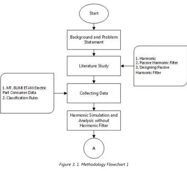
3.2 Methodology Flowchart ... 15
3.3 Background and Problem Statement ... 16
3.4 Literature Study ... 17
3.5 Collecting Data... 17
3.6 Harmonic Simulation & Analysis without Harmonic Filter ... 17
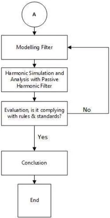
3.7 Modelling Filter ... 17
3.8 Harmonic Simulation & Analysis with Passive Harmonic Filter ... 18
3.9 Evaluation, is it complying with rules & standards? ... 18
3.10 Conclusion ... 18
CHAPTER 4 ... 19
DISCUSSION AND DATA ANALYSIS ... 19
4.1 General ... 19
4.2 Data collection ... 19
4.2.1 Ship Description ... 19
4.2.2 Propulsion Motors ... 20
4.2.3 Generator ... 21
4.3 Establishing and Simulation of Ship Electrical Network on ETAP Software ... 23
4.3.1 Establish Ship Electrical Network Data to ETAP Software ... 23
4.4 Harmonic Analysis & Simulation ... 23
4.5 Modelling Filter ... 25
4.6 Harmonic Simulation & Result ... 38
CHAPTER 5 ... 53
xiii
5.1 Conclusion ... 53
5.2 Recommendation... 58
REFERENCES ... 59
ATTACHMENT ... 61
xiv
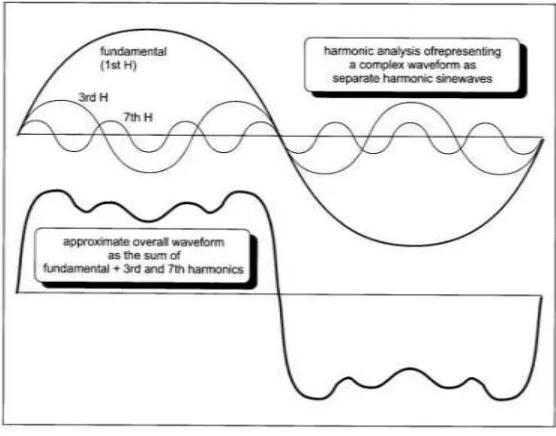
Figure 2. 1. Harmonic analysis of waveforms. ... 5
Figure 2. 2. Parallel Circuit Filter. ... 8
Figure 2. 3. Series Circuit Filter. ... 8
Figure 2. 4. a 3-Phase Passive Filter Circuit System. ... 9
Figure 2. 5. Harmonic Value based on harmonic order ... 10
Figure 2. 6. Harmonic Library for Variable Frequency Drive ... 12
Figure 2. 7. Harmonic Analysis Mode ... 12
Figure 2. 8. Harmonic Order Slider ... 13
Figure 2. 9. Edit Mode ... 13
Figure 2. 10. Passive Harmonic Filter Symbol ... 13
Figure 2. 11. Passive Harmonic Filter editor ... 14
Figure 3. 1. Methodology Flowchart 1 ... 15
Figure 3. 2. Methodology Flowchart 2 ... 16
Figure 4. 1. Variable Frequency Drive Data ... 21
Figure 4. 2. Bus Bar 1 Harmonic Value - Sailing Condition ... 25
Figure 4. 3. Bus Bar 2 Harmonic Value - Sailing Condition ... 26
Figure 4. 4. Bus5 Harmonic Value - Sailing Condition ... 26
Figure 4. 5. Bus10 Harmonic Value - Sailing Condition ... 26
Figure 4. 6. Bus11 Harmonic Value - Sailing Condition ... 27
Figure 4. 7. Bus12 Harmonic Value - Sailing Condition ... 27
Figure 4. 8. Bus13 Harmonic Value - Sailing Condition ... 27
Figure 4. 9. Bus14 Harmonic Value - Sailing Condition ... 28
Figure 4. 10. Cable15 Harmonic Value - Sailing Condition... 28
Figure 4. 11. Cable17 Harmonic Value - Sailing Condition... 28
Figure 4. 12. Harmonic Value - Sailing Condition ... 29
Figure 4. 13. Cable19 Harmonic Value - Sailing Condition... 29
Figure 4. 14. Cable78 Harmonic Value - Sailing Condition... 29
Figure 4. 15. T7 Harmonic Value - Sailing Condition ... 30
Figure 4. 16. T8 Harmonic Value - Sailing Condition ... 30
Figure 4. 17. Bus Bar 1 Harmonic Value - Maneuvering Condition ... 30
Figure 4. 18. Bus Bar 2 Harmonic Value - Maneuvering Condition ... 31
Figure 4. 19. Bus5 Harmonic Value - Maneuvering Condition ... 31
xv
Figure 4. 21. Bus12 Harmonic Value - Maneuvering Condition ... 32
Figure 4. 22. Bus13 Harmonic Value - Maneuvering Condition ... 32
Figure 4. 23. Bus14 Harmonic Value - Maneuvering Condition ... 32
Figure 4. 24. Cable15 Harmonic Value - Maneuvering Condition ... 33
Figure 4. 25. Cable17 Harmonic Value - Maneuvering Condition ... 33
Figure 4. 26. Cable18 Harmonic Value - Maneuvering Condition ... 33
Figure 4. 27. Cable 19 Harmonic Value - Maneuvering Condition ... 34
Figure 4. 28. Cable78 Harmonic Value - Maneuvering Condition ... 34
Figure 4. 29. T7 Harmonic Value - Maneuvering Condition... 34
Figure 4. 30. T8 Harmonic Value - Maneuvering Condition ... 35
Figure 4. 31. Modelling Filter - Capacitor and Inductor ... 36
Figure 4. 32. Sizing Single-Tuned Passive Filter ... 36
Figure 4. 33. Harmonic Load Flow Analysis ... 37
Figure 4. 34. Load Flow Analysis ... 38
Figure 4. 35. VTHD value comparison - Sailing Condition ... 39
Figure 4. 36. VTHD value comparison - Maneuvering Condition... 40
Figure 4. 37. Bus Bar 1 Harmonic value comparison - Sailing Condition ... 41
Figure 4. 38. Bus Bar 2 Harmonic value comparison - Sailing Condition ... 41
Figure 4. 39. Bus5 Harmonic value comparison - Sailing Condition ... 41
Figure 4. 40. Bus10 Harmonic value comparison - Sailing Condition ... 42
Figure 4. 41. Bus11 Harmonic value comparison - Sailing Condition ... 42
Figure 4. 42. Bus12 Harmonic value comparison - Sailing Condition ... 42
Figure 4. 43. Bus13 Harmonic value comparison - Sailing Condition ... 43
Figure 4. 44. Bus14 Harmonic value comparison - Sailing Condition ... 43
Figure 4. 45. Cable15 Harmonic value comparison - Sailing Condition ... 43
Figure 4. 46. Cable17 Harmonic value comparison - Sailing Condition ... 44
Figure 4. 47. Cable18 Harmonic value comparison - Sailing Condition ... 44
Figure 4. 48. Cable19 Harmonic value comparison - Sailing Condition ... 44
Figure 4. 49. Cable78 Harmonic value comparison - Sailing Condition ... 45
Figure 4. 50. T7 Harmonic value comparison - Sailing Condition ... 45
Figure 4. 51. T8 Harmonic value comparison - Sailing Condition ... 45
Figure 4. 52. Bus Bar 1 Harmonic value comparison - Maneuvering Condition .. 46
Figure 4. 53. Bus Bar 2 Harmonic value comparison - Maneuvering Condition 46 Figure 4. 54. Bus5 Harmonic value comparison - Maneuvering Condition ... 46
Figure 4. 55. Bus10 Harmonic value comparison - Maneuvering Condition ... 47
Figure 4. 56. Bus11 Harmonic value comparison - Maneuvering Condition ... 47
xvi
Figure 4. 60. Cable15 Harmonic value comparison - Maneuvering Condition .... 48 Figure 4. 61. Cable17 Harmonic value comparison - Maneuvering Condition .... 49 Figure 4. 62. Cable18 Harmonic value comparison - Maneuvering Condition .... 49 Figure 4. 63. Cable19 Harmonic value comparison - Maneuvering Condition .... 49 Figure 4. 64. Cable78 Harmonic value comparison - Maneuvering Condition .... 50 Figure 4. 65. T7 Harmonic value comparison - Maneuvering Condition ... 50 Figure 4. 66. T8 Harmonic value comparison - Maneuvering Condition ... 50
Figure 5. 1. Harmonic Spectrum Report – Sailing Condition, No Harmonic Filter ... 53 Figure 5. 2. Harmonic Waveform Report – Sailing Condition, No Harmonic Filter ... 54 Figure 5. 3. Harmonic Spectrum Report – Maneuvering Condition, No Harmonic Filter ... 54 Figure 5. 4. Harmonic Waveform Report – Maneuvering Condition, No
Harmonic Filter ... 55 Figure 5. 5. Designing Single-Tuned Passive Harmonic Filter ... 55 Figure 5. 6. Harmonic Waveform Report – Sailing Condition, with Passive
Harmonic Filter ... 57 Figure 5. 7. Harmonic Spectrum Report – Sailing Condition, with Passive
xvii
LIST OF TABLE
Table 2. 1. Some Effects of Harmonics ... 6 Table 2. 2. Tuning Orders in an applied tuning factor ... 14
Table 4. 1. Diesel Engine Data for Past-Design of Propulsion Motor ... 20 Table 4. 2. A 3-Phase Induction Motor Data for Present-Design of Propulsion Motor ... 21 Table 4. 3. Diesel Generator of Past-Design ... 22 Table 4. 4. Diesel Generator of Present-Design ... 22 Table 4. 5. Diesel Generator of Present-Design. ... 23 Table 4. 6. Harmonic Load Flow Analysis Report - Sailing Condition, No
xviii
1
CHAPTER 1
INTRODUCTION
1.1 Background
In a ship, there is a system that is important so that the ship can move, one of which is the propulsion system. The use of diesel engine propulsion system is a conventional system. Diesel motor paired with a shaft as a connector between the diesel engine with a propeller.
However, along with developments in technology, ship propulsion systems have many different types of propulsion systems. One of them using an electric propulsion system using electric motors. There are 2 types of electric motors that will be used for research of electric propulsion system, there are; DC motors and three-phase induction motor.
This thesis will discuss electric propulsion system on the tanker using a three-phase induction motor as a replacement for conventional propulsion systems. However, in its application, there is interference on frequency of the electricity generated by the electric propulsion system. The quality and security of its voltage supply is crucial to the safety of any marine vessel. With the increasing use of AC and DC electric drives for applications such as electric propulsion, this has become an even greater issue. Electric propulsion provides significant benefits, such as lower running costs, less maintenance, reduced manpower, greater redundancy, lower emissions, improved maneuverability (with podded or azimuth type propulsors) and increased cargo carrying capabilities. But by drawing current in a non-linear or non-sinusoidal manner, electric propulsion can introduce excessive levels of both current and voltage harmonics. [1]
One of them is frequency defects or harmonic due to the use of power electronic converter. Electronic power converter has functions to control the speed of three-phase induction motor. As a result of frequency defects or harmonic itself could damage equipment that uses electrical energy that is connected directly to the electrical system on board. The input current to a static power converter has, in general, a high harmonic content due to the wav the current is switched (chopped)from phase to phase. Harmonic currents are important because they cause distortion of the supply voltage waveform which
1 I. C. Evans, A. H. Hoevenaars, P.Eng, Member, IEEE. Meeting Harmonic Limits on Marine
may result in the malfunction and additional heating of other equipment connected to the supply system. The size and frequencies of the harmonic currents and voltages depend on the converter type, the pulse number and method of control (e.g. synchroconverter, cycloconverter or PWM).
To reduce the problem of defective frequency wave or harmonic, one of them can be solved by installing a passive harmonic filter. Passive harmonic filter serves to repair defects caused waves of components or other variables that could disrupt the working frequency.
1.2 Problem Statement
The passive harmonic filter design can overcome the problem of frequency wave defects that caused from using power electronic converters that are used to control the speed of three-phase induction motor in the propulsion system on board, then some induction motor load (e.g. exhaust and supply fan), and another intermittent load.
Based on the explanation above, the main problem will be discussed is as followed;
1. How much harmonic on ship electrical system before installation of Passive Harmonic Filter?
2. How to configure Passive Harmonic Filter appropriately to overcome the harmonic on ship electrical system?
3. How much harmonic on ship electrical system after installation of Passive Harmonic Filter?
1.3 Problem Limitations
In order to meet expected results, this thesis need to have limitations so the aim of this thesis can be achieved on time, the limitations are as follows;
1. This thesis is focusing on how to calculate needed of Passive Harmonic Filter in the tanker ship due to harmonic on ship electrical system.
2. Cost and economic factor are not included.
3. Changes to the design, EPM value, and ship structure are not discussed here in this thesis.
1.4 Objectives
The objectives of this thesis are;
3
2. To obtain an appropriate design of Passive Harmonic Filter. 3. To obtain value of harmonic after installation of Passive Harmonic
Filter.
1.5 Benefits
The benefits of this thesis are;
1. The data that have been obtained can be used as a reference in developing the Electric Propulsion System on ship.
5
CHAPTER 2
LITERATURE STUDY
2.1 Overview
2.1.1 Harmonic
Generally harmonic frequencies are integer multiples (e.g. 3, 5, 7, 11, 13, 15, etc.) of the fundamental (supply) frequency. Hence, a 7th harmonic in a 50 Hz a.c. voltage has a frequency of 350 Hz and an 11th has a frequency of 550 Hz. Harmonic amplitudes are roughly the reciprocal of the harmonic number, i.e. 20% (1/5) for the 5th, 14.3% for the 7th, 9.1% for the 11th, etc. The particular shape of the resulting supply voltage will depend on harmonic currents causing additional harmonic voltages in the supply reactance (inductive and/or capacitive). 2
Some harmonics are eliminated by careful system design e.g. by adding more circuit inductance, using phase-shifting transformers (star-star and (star-star-delta) and increasing the converter pulse number. The 30o phase-shifted transformers effectively double the current pulses drawn by the motor so a 6-pulse converter system appears to be 12 pulse as viewed from the supply point. See example in Figure 2. 1.
2 Dennis T. Hall B.A. PRACTICAL MARINE ELECTRICAL KNOWLEDGE. 1984.
Figure 1.
For a generator sinusoidal a.c. voltage waveform with identical positive and negative shapes, all even numbered harmonics are cancelled 3out. In a three-phase a.c. system, all harmonics that are a multiple of three are also automatically cancelled. That leaves harmonic numbers of 5th, 7th, 11th, 13th, 17th.etc. as potential problems. For a pair of six-pulse synchroconverters supplied by a pair of phase-shifted transformers the significant harmonic problem is reduced to the 5th, 11th and 17th. 2
The harmonic content of the a.c. input to a synchroconverter also has components that are related to the motor operating frequency. The d.c. link reactor coil reduces the ripple in the link current so that the effect on the a.c. supply side is reduced.
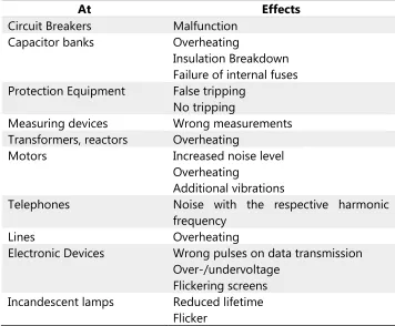
There are also some effects effects of Harmonics, there are as follows;3
Table 2. 1. Some Effects of Harmonics 3
At Effects
Circuit Breakers Malfunction
Capacitor banks Overheating
Insulation Breakdown Failure of internal fuses Protection Equipment False tripping
No tripping
Measuring devices Wrong measurements
Transformers, reactors Overheating
Motors Increased noise level
Overheating
Additional vibrations
Telephones Noise with the respective harmonic
frequency
Lines Overheating
Electronic Devices Wrong pulses on data transmission Over-/undervoltage
Flickering screens Incandescent lamps Reduced lifetime
Flicker
2 Dennis T. Hall B.A. PRACTICAL MARINE ELECTRICAL KNOWLEDGE. 1984.
7
The effects of harmonics are not only that, there are also several technical impacts 4 as follows;
• Overloads on the distribution system due to the increase in rms current.
• Overload on the neutral conductor due to the summing of the third and its multiple-order harmonics created by single-phase loads.
• Overloads, vibrations, and premature aging of generators, transformers, motors, and so on, and capacitor of power factor (PF) correction equipment.
• Distortion of the supply voltage capable og disturbing sensitive loads
• Disturbances on communication networks and telephone lines.
2.2 Harmonic Filter
To minimize the size of voltage distortion it is necessary to connect filters which are tuned to the troublesome harmonics. The filters are combination sets of inductance (L) and capacitance (C) each resonantly tuned to a particular frequency in a series/parallel circuit. Additionally, some resistance (R) is included to act as a harmonic current limiting (damping) effect. 2
The simplest way to view the overall system is to consider that the converter injects harmonics while the filter absorbs them. Filtering is not perfect over the variable frequency range so the harmonic problem is not completely solved but is minimized.
Practical harmonic installations in power systems are physically large and will create power losses and heat in the components.
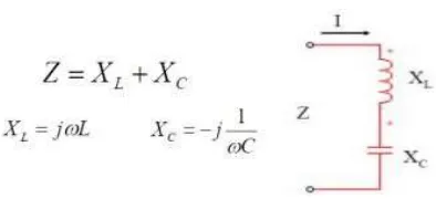
2.2.1 Passive Filter
Passive filter is a series of parallel or in series between the components of the inductor (L) and capacitor (C). The filter circuit can be tuned to a specific frequency where the impedance of the inductor to be equal to the impedance of the capacitor. The effectiveness of filters work
2 Dennis T. Hall B.A. PRACTICAL MARINE ELECTRICAL KNOWLEDGE. 1984.
is determined by changes in electrical network impedance, and accurate study are required prior to filter installation. 5
Parallel Circuit Filter
If given a voltage source with the resonance frequency, Fr, where |XL| = |XC|
XL + XC = 0, so that;
- Very large impedance Z - The current I approaches zero Series Circuit Filter
If given a voltage source with the resonance frequency, Fr, where | XL | = | XC |
XL + XC = 0, so that;
- Impedance Z = 0
- Current I have a greater value
5 Suryono, Sutedjo, M. Zaenal Efendi, Andrias Ade, Sigit Prasetya. Filter Pasif Untuk
Mereduksi dan Memanfaatkan Harmonisa Ke-5 dan 7 pada Beban Konverter 6 Pulsa Sebagai Sumber Energi Dengan Menggunakan Full Bridge DC-DC Converter dan Inverter.
Figure 2.
Figure 3.
Figure 2. 2. Parallel Circuit Filter. 5
9
And installation of passive filters as in Figure 2. 4, there are two filters (filter harmonics 5th and 7th harmonic filter).
Because it uses the three-phase source, then each phase is established with passive harmonic filter circuits.
2.3 Harmonic Limit Standard
2.3.1 Classification Rules
DNV GL Rules I, Part 1, Chapter 3 - Electrical Installations. 63 • Section 1 – General Requirements and Guidance
F.2.1
“In systems without substantial static converter load and supplied by synchronous generators, the total voltage harmonic distortion shall not exceed 5 %.”
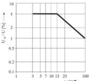
F.2.2
“In systems fed by static converters, and systems in which the static converter load predominates, for single harmonics in permanence the limit values indicated in Fig. 1.1 apply.
The total harmonic distortion shall not exceed 8 %.”
5 Suryono, Sutedjo, M. Zaenal Efendi, Andrias Ade, Sigit Prasetya. Filter Pasif Untuk
Mereduksi dan Memanfaatkan Harmonisa Ke-5 dan 7 pada Beban Konverter 6 Pulsa Sebagai Sumber Energi Dengan Menggunakan Full Bridge DC-DC Converter dan Inverter.
6 DNV GL SE. Electrical Installations (I-1-3). 2014.
Figure 4.
• Section 3 – Power Supply Installations6 B.2.2 Waveform
“The waveform of the line-to-line no-load voltage shall be as close as possible to sinusoidal. The deviation from a sinusoidal fundamental shall at no time exceed 5 % relative to the peak value of the fundamental. The RMS values of the phase voltages shall not differ from each other by more than 0.5 % under balanced load conditions.
If the star points of generators running in parallel are earthed, the waveforms of the phase voltages should coincide. It is to ensure that the transient current due to harmonics in the starpoint connection does not exceed 20 % of the rated current of the machine with the lowest output.” • Section 13 - Additional Rules for Electrical Main Propulsion Plants B.3.1
“The effects of the harmonics of currents and voltages shall be taken into consideration for the design of the propulsion motors.”
C.5 Filter Circuits C.5.1
“If filter circuits are used to reduce the harmonics, these circuits must be protected against overload and short circuit.”
C.5.2
“Filters shall be monitored for failure.”
6 DNV GL SE. Electrical Installations (I-1-3). 2014.
11
C.5.3
“The operating instructions shall document which propulsion settings and generator combinations are admissible after failure of one or all of the filters. This shall be verified by means of a THD measurement.”
C.5.4
“Filters shall function properly in all propulsion settings and grid configurations and shall not lead to increases in voltage or current. This shall be verified through measurements during the sea trial.”
• Section 20 – Electrical Equipment
A.1.13 Operation in network with semiconductor converters
“Electric machines operating in networks containing semiconductor converters shall be designed for the expected harmonics of the system. A sufficient reserve shall be considered for the temperature rise, compared with a sinoidal load.”
C.4.3
“In systems with high levels of harmonics, capacitors shall be protected against overloading by the use of series inductors and/or the selection of a higher capacitor voltage rating.”
2.4 Passive Filter Design with ETAP Software
This thesis will use a software ETAP to get the simulation and conclusion for the result. Before designing a passive harmonic filter, it needs to analyze Harmonic Load Flow from ship electrical system itself. The process of Harmonic Load Flow Analysis and Designing Passive Filter with ETAP 7 will be explained below.
2.4.1 Harmonic Load Flow Analysis
To generate a Harmonic Load Flow Analysis, a whole ship electrical network system must be established on ETAP diagram. After established, then fill required harmonic current source specification. This harmonic
source comes from a non-linear source. In this case harmonic are come from variable frequency drive.
Then, do harmonic load flow analysis.
Do harmonic analysis for every harmonic order. Before continuing to next order, the harmonic distortion data need to be collected so the filter design are specific to certain order.8
8 ETAP Version 12.6.0
Figure 2. 6. Harmonic Library for Variable Frequency Drive 8
13
2.4.2 Passive Harmonic Filter Design
After harmonic distortion data from all harmonic orders are collected, a Passive Harmonic Filter can be designed.
First, back to edit mode.
Then put the harmonic filter on the bus bar that have a significantly large number of harmonic distortion that can occur another electrical machines or electrical equipment.8
8 ETAP Version 12.6.0
Figure 2. 8. Harmonic Order Slider 8
Figure 2. 9. Edit Mode 8
After placing the filter, then determine filter type, then size the filter for required harmonic order, fill harmonic current, fill Existing and Desired Power Factor (PF), and fill Load Factor on Figure 2. 11.
Then, click size filter and ETAP will automatically calculate capacitor and inductor that will be substituted to filter by click substitute.
But the harmonic order were not exactly the value of its harmonic frequency integer (e.g. 5th order harmonic value are not exactly 5). The tuning order to be applied in sizing the single-tuned filter are shown in Table 2. 2.8 9
8 ETAP Version 12.6.0
9 Young-Sik Cho & Hanju Cha. Single-tuned Passive Harmonic Filter Design Considering
Variances of Tuning and Quality Factor. 2011.
Figure 2. 11. Passive Harmonic Filter editor 8
15
CHAPTER 3
RESEARCH METHODOLOGY
3.1 General
Methodology should be done to accomplish the objectives on this thesis. A good methodology became one of the most important points. This methodology will explain what processes should be done, starts from the background and the problem statement, the data what should have, then how the data is processed, until purpose of this thesis.
3.2 Methodology Flowchart
3.3 Background and Problem Statement
This stage is an early stage to construct the thesis, questions and problems are being prepared specifically in order to determine the specific objectives of this thesis. The content of the thesis is to overcome the statement of the problems mentioned earlier and it will be done by collect some information about the problems. Therefore, the purpose of this thesis can be understood in this stage.
17
3.4 Literature Study
Right after the problems is raised, a literature study is performed. In this stage, literature will be used to connect the problems with existing theories and facts from various sources. The study of literature is done by reading papers, journals, thesis, media and literature books that relates and able to support this thesis.
3.5 Collecting Data
After literature study which support the thesis has been done, collecting data is being performed. Data collection is done by gather information to develop the design, most of data is available from the ship design data, classification rules, standards, propulsion motor, and filter specification. The data which may support this thesis is the engine specification, electric motor for propulsion unit, auxiliary unit specification, filter specification, classification and standards.
3.6 Harmonic Simulation & Analysis without Harmonic Filter
This stage is about create and constructing ship electrical network system, many data from power source to power output have to be constructed due to preparing simulation for Harmonic Load Flow Analysis before Designing a Passive Harmonic Filter. Then do a simulation to obtain a data from ship electrical network system about how much harmonic and distortion that happen on the electrical system. Then the obtained data is required to be analyzed for Designing a Passive Harmonic Filter.
3.7 Modelling Filter
After getting result of simulation, it requires to determine harmonic current source specification that came from non-linear source. This thesis is specifically directing this non-linear source to power electronic converter that in this case are using variable frequency drive. Then do a harmonic load flow analysis, do load flow simulation of every harmonic order. The last is collect harmonic distortion data of all harmonic order
3.8 Harmonic Simulation & Analysis with Passive Harmonic Filter
After modelling filter, this stage is similar to Harmonic Simulation & Analysis step. But, the difference is while running the simulation, the ship electrical network system is already fitted with passive filter that will reduce the harmonic and distortion that will be compared to simulation without installing a passive filter.3.9 Evaluation, is it complying with rules & standards?
This is the important point of this thesis, evaluation from the analysis result of installing and simulate passive filter on the ship electrical network system must be can reduce the harmonic and distortion on the system, and complying with rules and standards.
3.10 Conclusion
19
CHAPTER 4
DISCUSSION AND DATA ANALYSIS
4.1 General
In this chapter, the data analysis and discussion, there are several steps that need to be explained. The design process of the passive harmonic filter that will be applied to electrical system on the ship. The data required to support the process of this thesis are MT. BUMI ETAM electrical system include the electrical system network, Main Switch Board network, specific electric consumer for every condition (e.g. sailing, maneuvering, and so on). This is the initial stage to establish the ship electrical network in ETAP software to do a simulation. Then the result from the simulation will be used to design passive harmonic filter.
After getting the result of simulation, this first result data are not equipped with a harmonic filter. So, the harmonic value must be have a high value due to the use of variable frequency drive. The next stage after designing and installing passive harmonic filter, a simulation have to be done to know the result after applying a passive harmonic filter with a harmonic value that occur in the ship. This data will be compared by using a chart to identify the harmonic value of each bus and branch in before and after installing the passive harmonic filter.
Goal of this thesis is to reduce the harmonic value (THD) according to classification requirements that the THD value need to be lower than 5%.
4.2 Data collection
4.2.1 Ship Description
Ship description is a general data such as ship particular, ship propulsion systems, machinery and electrical system, electrical consumen, electrical power consumer for each conditions.
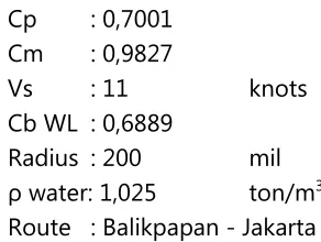
Name : MT. BUMI ETAM Type : Product Oil Tanker
GT : 1170 ton
Lpp : 66 m
Lwl : 67,98 m
B : 12 m
H : 4,9 m
T : 4,3 m
Cp : 0,7001 Cm : 0,9827
Vs : 11 knots
Cb WL : 0,6889
Radius : 200 mil ρ water: 1,025 ton/m3 Route : Balikpapan - Jakarta
4.2.2 Propulsion Motors
In the beginning, this ship was used to be designed using a diesel engine as propulsion motor. The diesel engine specification are as follows;
Table 4. 1. Diesel Engine Data for Past-Design of Propulsion Motor
When changing from diesel engine into an electric 3-Phase induction motor then some equipment’s that using electrical power to support the diesel engine are mostly eliminated. Those eliminated equipment’s are as follows;
1. HFO Separator 2. HFO Pre-Heater 3. HFO Transfer Pump 4. HFO Stand-by Pump 5. LO Transfer Pump 6. LO Separator Unit 7. LO Pre-Heater Separator 8. LT/HT Standby Pump
WARTSILA 4520
Power (kW) 800
RPM 1000
SFOC (g/kWh) 197
Dimension (L x W x 2510 x 1483 x 2073
Weight (ton) 7,2
21
The new propulsion motor are using 3-Phase Induction Motor. The specification are as follows;
Table 4. 2. A 3-Phase Induction Motor Data for Present-Design of Propulsion Motor
To control the speed of this electric 3-phase induction motor, the Variable Frequency Drive (VFD) are needed to be installed on the motor. Selected VFD for this drive are as follows;
4.2.3 Generator
The propulsion motor is now needed to be supplied by electricity power. Electricity in this ship were generated by a diesel generator. The past designed generators must be replaced due to increase of electric power consumers, especially by the propulsion motor.
ABB M3BP 450LC 6
Power (kW) 800
RPM 994
Current IN (Amp) 1469
Efficiency (1/
2 Load – Full 96,8 %
Torque TN (Nm) 7682
Weight (ton) 4,8
Total power consumption on this ship before and after installed 3-Phase induction motor, the value are taken from highest power consumption while ship on various operating condition;
• Before :- 56 kW (On Sailing condition) - 66,6 kW (On Maneuvering condition) - 137,8 kW (On Cargo Handling condition) - 65,1 kW (On Port condition)
• After :- 708,2 kW (On Sailing condition) - 708,3 kW (On Maneuvering condition) - 96,9 kW (On Cargo Handling condition) - 57,7 kW (On Port condition)
Past-design generators are only use 2 diesel generators with specification as follows;
Table 4. 3. Diesel Generator of Past-Design
Total generated power from this generator are;
▪ Power x Set = 86 x 2 = 172 kW
With new total electric power consumption that increased by electric propulsion system, Present-design generators are upgraded and added some small generators due to significant power consumption on operating conditions;
Table 4. 4. Diesel Generator of Present-Design Caterpillar 4.4
Power (kW) 86
RPM 1500
Frequency (Hz) 50
Total set (Unit) 2
CUMMINS C650 D5A
Power (kW) 409
RPM 1500
Frequency (Hz) 50
23
Total generated power from this generator are;
▪ Power x Set = 409 x 2 = 818 kW
This generator are only used for sailing and maneuvering conditions due to high power electric consumption.
Table 4. 5. Diesel Generator of Present-Design.
Total generated power from this generator are;
▪ Power x Set = 90 x 2 = 180 kW
This generator are only used for cargo handling and at port due to small power amount of electric consumption on this condition.
4.3 Establishing and Simulation of Ship Electrical Network on ETAP
Software
4.3.1 Establish Ship Electrical Network Data to ETAP Software
The electrical network that will be established on ETAP software are collected from Main Switchboard and each of junction power of each deck as follows;1. Main Switchboard (Junction Lightning, Steering Gear, and another equipment also included here)
2. Junction Power Engine Room 3. Junction Power Main Deck
4. Junction Power Poop Deck + Boat Deck
5. Junction Power Bridge Deck + Navigation Deck
Ship electrical network simulation data are attached at the end of this thesis.
4.4
Harmonic Analysis & Simulation
After ship electrical network established on ETAP, then harmonic load flow analysis are need to be simulate to get the harmonic value and
CUMMINS C125 D5
Power (kW) 90
RPM 1500
Frequency (Hz) 50
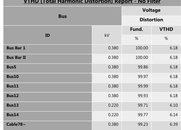
where did the harmonic happen on the electrical network. The report will show if there is any harmonic value that over the limit that already set. The limit are set to 5% according to 5% as DNV GL Rules standards; DNV GL Rules I, Part 1, Chapter 3 - Electrical Installations. 6
• Section 1 – General Requirements and Guidance F.2.1
“In systems without substantial static converter load and supplied by synchronous generators, the total voltage harmonic distortion shall not exceed 5 %.”
Table 4. 6. Harmonic Load Flow Analysis Report - Sailing Condition, No Harmonic Filter VTHD (Total Harmonic Distortion) Report - No Filter
Bus
Voltage
Distortion
ID kV
Fund. VTHD
% %
Bus Bar 1 0.380 100.00 6.18
Bus Bar II 0.380 100.00 6.18
Bus5 0.380 99.86 6.18
Bus10 0.380 99.97 6.18
Bus11 0.380 99.99 6.18
Bus12 0.380 99.93 6.18
Bus13 0.220 99.71 6.10
Bus14 0.220 99.77 6.14
Cable78~ 0.380 99.23 6.39
Indicates buses with THD (Total Harmonic Distortion) exceeding the limit
In the other condition; cargo handling and at port, there are no harmonic value after running a simulation. A complete report of the simulation can be found on the attachment of this thesis.
25
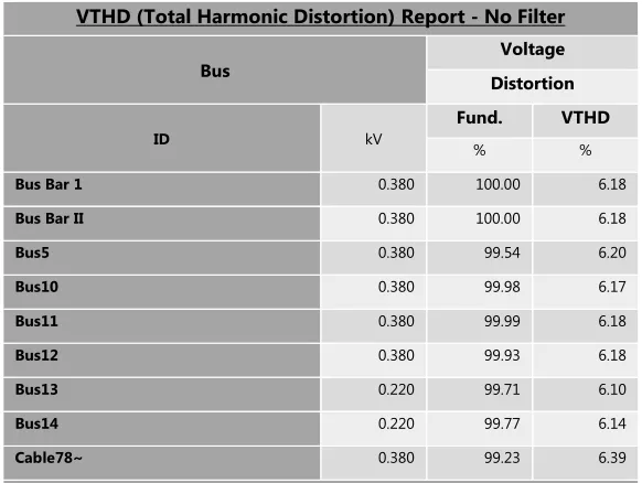
Table 4. 7. Harmonic Load Flow Analysis Report – Maneuvering Condition – No Harmonic Filter
VTHD (Total Harmonic Distortion) Report - No Filter
Bus
Voltage
Distortion
ID kV
Fund. VTHD
% %
Bus Bar 1 0.380 100.00 6.18
Bus Bar II 0.380 100.00 6.18
Bus5 0.380 99.54 6.20
Bus10 0.380 99.98 6.17
Bus11 0.380 99.99 6.18
Bus12 0.380 99.93 6.18
Bus13 0.220 99.71 6.10
Bus14 0.220 99.77 6.14
Cable78~ 0.380 99.23 6.39
Indicates buses with THD (Total Harmonic Distortion) exceeding the limit
4.5
Modelling Filter
There are 6 types of harmonic filter that provided by ETAP. But only the single-tuned harmonic filter can be used for specific harmonic orders. This will have an advantage to minimized the harmonic distortion to meet rules standard.
In order to design a single-tuned harmonic filter, then the specific harmonic order need to determined based on the highest harmonic value.
• Sailing Condition
0.00 2.00 4.00 6.00
5 7 11 13 17 19 23 25 29 31 35 37 41 43 47 49
Ma
g. (%
)
Harmonic Order
Bus Bar 1
No Filter
0 2 4 6
5 7 11 13 17 19 23 25 29 31 35 37 41 43 47 49
Ma g. (% ) Harmonic Order
Bus5
No Filter 0 2 4 65 7 11 13 17 19 23 25 29 31 35 37 41 43 47 49
Ma
g. (%
)
Harmonic Order
Bus Bar 2
No Filter
0 2 4 6
5 7 11 13 17 19 23 25 29 31 35 37 41 43 47 49
Ma g. (% ) Harmonic Order
Bus10
No FilterFigure 4. 3. Bus Bar 2 Harmonic Value - Sailing Condition
Figure 4. 4. Bus5 Harmonic Value - Sailing Condition
27 0 2 4 6
5 7 11 13 17 19 23 25 29 31 35 37 41 43 47 49
Ma g. (% ) Harmonic Order
Bus11
No Filter 0 2 4 65 7 11 13 17 19 23 25 29 31 35 37 41 43 47 49
Ma g. (% ) Harmonic Order
Bus12
No Filter 0 2 4 65 7 11 13 17 19 23 25 29 31 35 37 41 43 47 49
Ma g. (% ) Harmonic Order
Bus13
No FilterFigure 4. 6. Bus11 Harmonic Value - Sailing Condition
Figure 4. 7. Bus12 Harmonic Value - Sailing Condition
0 2 4 6
5 7 11 13 17 19 23 25 29 31 35 37 41 43 47 49
Ma g. (% ) Harmonic Order
Bus14
No Filter 0.00 2.00 4.00 6.005 7 11 13 17 19 23 25 29 31 35 37 41 43 47 49
Ma g. (% ) Harmonic Order
Cable15
No Filter 0.00 1.00 2.00 3.00 4.005 7 11 13 17 19 23 25 29 31 35 37 41 43 47 49
Ma g. (% ) Harmonic Order
Cable17
No FilterFigure 4. 9. Bus14 Harmonic Value - Sailing Condition
Figure 4. 10. Cable15 Harmonic Value - Sailing Condition
29 0.00 0.50 1.00 1.50 2.00
5 7 11 13 17 19 23 25 29 31 35 37 41 43 47 49
Ma g. (% ) Harmonic Order
Cable18
No Filter 0.00 1.00 2.00 3.00 4.005 7 11 13 17 19 23 25 29 31 35 37 41 43 47 49
Ma g. (% ) Harmonic Order
Cable19
No Filter 0.00 2.00 4.00 6.005 7 11 13 17 19 23 25 29 31 35 37 41 43 47 49
Ma g. (% ) Harmonic Order
Cable78
No FilterFigure 4. 12. Harmonic Value - Sailing Condition
Figure 4. 13. Cable19 Harmonic Value - Sailing Condition
• Maneuvering Condition 0.00 0.50 1.00 1.50 2.00
5 7 11 13 17 19 23 25 29 31 35 37 41 43 47 49
Ma g. (% ) Harmonic Order
T7 (Transformer)
No Filter 0.00 0.50 1.00 1.50 2.005 7 11 13 17 19 23 25 29 31 35 37 41 43 47 49
Ma g. (% ) Harmonic Order
T8 (Transformer)
No Filter 0 2 4 65 7 11 13 17 19 23 25 29 31 35 37 41 43 47 49
Ma
g. (%
)
Harmonic Order
Bus Bar 1
No Filter
Figure 4. 15. T7 Harmonic Value - Sailing Condition
Figure 4. 16. T8 Harmonic Value - Sailing Condition
31
0 2 4 6
5 7 11 13 17 19 23 25 29 31 35 37 41 43 47 49
Ma
g. (%
)
Harmonic Order
Bus Bar 2
No Filter
0 2 4 6
5 7 11 13 17 19 23 25 29 31 35 37 41 43 47 49
Ma g. (% ) Harmonic Order
Bus5
No Filter 0 2 4 65 7 11 13 17 19 23 25 29 31 35 37 41 43 47 49
Ma g. (% ) Harmonic Order
Bus10
No FilterFigure 4. 18. Bus Bar 2 Harmonic Value - Maneuvering Condition
Figure 4. 19. Bus5 Harmonic Value - Maneuvering Condition
0 2 4 6
5 7 11 13 17 19 23 25 29 31 35 37 41 43 47 49
Ma g. (% ) Harmonic Order
Bus12
No Filter 0 2 4 65 7 11 13 17 19 23 25 29 31 35 37 41 43 47 49
Ma g. (% ) Harmonic Order
Bus14
No Filter 0 2 4 65 7 11 13 17 19 23 25 29 31 35 37 41 43 47 49
Ma g. (% ) Harmonic Order
Bus13
No FilterFigure 4. 21. Bus12 Harmonic Value - Maneuvering Condition
Figure 4. 22. Bus13 Harmonic Value - Maneuvering Condition
33 0.00 0.05 0.10 0.15 0.20
5 7 11 13 17 19 23 25 29 31 35 37 41 43 47 49
Ma g. (% ) Harmonic Order
Cable15
No Filter 0.00 0.05 0.10 0.155 7 11 13 17 19 23 25 29 31 35 37 41 43 47 49
Ma g. (% ) Harmonic Order
Cable17
No Filter 0.00 0.01 0.01 0.02 0.025 7 11 13 17 19 23 25 29 31 35 37 41 43 47 49
Ma g. (% ) Harmonic Order
Cable18
No FilterFigure 4. 24. Cable15 Harmonic Value - Maneuvering Condition
Figure 4. 25. Cable17 Harmonic Value - Maneuvering Condition
0.00 0.05 0.10 0.15 0.20 0.25
5 7 11 13 17 19 23 25 29 31 35 37 41 43 47 49
Ma g. (% ) Harmonic Order
Cable19
No Filter 0.00 1.00 2.00 3.00 4.005 7 11 13 17 19 23 25 29 31 35 37 41 43 47 49
Ma g. (% ) Harmonic Order
Cable78
No Filter 0.00 0.00 0.00 0.01 0.015 7 11 13 17 19 23 25 29 31 35 37 41 43 47 49
Ma g. (% ) Harmonic Order
T7 (Transformer)
No FilterFigure 4. 27. Cable 19 Harmonic Value - Maneuvering Condition
Figure 4. 28. Cable78 Harmonic Value - Maneuvering Condition
35
Mag (%) is represent the harmonic current/voltage magnitudes in Amps/Volts on the fundamental current/voltage base.
Based on the data above, the harmonic value are majorly happened on 11th harmonic order. So, the passive filter that will be installed are focused on reducing harmonic on 11th order.
First, the filter must be sized, and below are how to fill the value of each variable;
• Capacitor kvar, µF, are determined from filter sizing.
• Capacitor Rated kV, Max. kV, are determined based on electrical network system. This determined value can be have a greater value due to protect the system from overload. • Inductor XL1 value, are determined from filter sizing.
• Inductor Q Factor, Max. I, are determined based on electrical network system. This determined value can be changed gradually due to get the best result after doing another simulation while a passive filter are connected to the system. 0.00
0.00 0.00 0.01 0.01
5 7 11 13 17 19 23 25 29 31 35 37 41 43 47 49
Ma g. (% ) Harmonic Order
T8 (Transformer)
No FilterFigure 4. 31. Modelling Filter - Capacitor and Inductor
37
To get the value of Capacitor kvar, µF, and Inductor XL1 value, it need to do a load flow simulation to get a PF value and a Load MVA value, while harmonic order and harmonic current are determined by doing a harmonic load flow analysis.
The result shows the cable that connecting Bus Bar 1 – VFD1 – 3-Phase Propulsion Motor are the highest value of harmonic current on the 11th order. This value then substituted to harmonic current and filter sizing. This value has a same amount on both condition (Sailing and Maneuvering).
Load flow analysis are needed to get the value of power factor (PF) for the same place or Cable78 (The cable that connecting Bus Bar 1 – VFD1 – 3-Phase Propulsion Motor). This value will be substituted to harmonic filter sizing to get a correction so the filter will increase the PF value.
4.6
Harmonic Simulation & Result
After modelling filter, the ship electrical network system is already fitted with a passive filter that will reduce the harmonic and distortion. This result will be compared to simulation without installing a passive filter. This is the important point of this thesis, evaluation from the result of installing and simulate passive filter on the ship electrical network system must be can reduce the harmonic and
39
distortion on the system, and harmonic value shall not exceed 5% 6 complying with rules and standards.
Below are VTHD report of simulation with passive filter installed; • Sailing Condition
Table 4. 8. Harmonic Load Flow Analysis Report – Sailing Condition, With Passive Filter VTHD (Total Harmonic Distortion) Report - Passive Filter
Bus Voltage
Distortion
ID kV Fund. VTHD
% %
Cable78~ 0.380 99.23 2.72
Indicates buses with THD (Total Harmonic Distortion) exceeding the limit
6 DNV GL SE. Electrical Installations (I-1-3). 2014.
0.00 1.00 2.00 3.00 4.00 5.00 6.00 7.00 VT H D (% )
VTHD (Total Harmonic Distortion) - Sailing
No Filter Passive Filter
• Maneuvering Condition
Table 4. 9. Harmonic Load Flow Analysis Report – Maneuvering Condition, With Passive Filter
VTHD (Total Harmonic Distortion) Report - Passive Filter
Bus Voltage
Distortion
ID kV Fund. VTHD
% %
Cable78~ 0.380 99.23 2.72
Indicates buses with THD (Total Harmonic Distortion) exceeding the limit
Both from sailing and maneuvering condition the VTHD value are reduced and mostly the VTHD value are disappear. But only Cable78 that has still VTHD value.
0.00 2.00 4.00 6.00 8.00
VT
H
D
(%
)
VTHD (Total Harmonic Distortion)
-Maneuvering
No Filter Passive Filter
41
And below are the graphs that comparing between no filter situation and with passive filter situation;
• Sailing Condition
0.00 2.00 4.00 6.00
5 7 11 13 17 19 23 25 29 31 35 37 41 43 47 49
Ma
g. (%
)
Harmonic Order
Bus Bar 1
No Filter Passive Filter
0 2 4 6
5 7 11 13 17 19 23 25 29 31 35 37 41 43 47 49
Ma
g. (%
)
Harmonic Order
Bus Bar 2
No Filter Passive Filter
0 2 4 6
5 7 11 13 17 19 23 25 29 31 35 37 41 43 47 49
Ma
g. (%
)
Harmonic Order
Bus5
No Filter Passive Filter
Figure 4. 37. Bus Bar 1 Harmonic value comparison - Sailing Condition
Figure 4. 38. Bus Bar 2 Harmonic value comparison - Sailing Condition
0 2 4 6
5 7 11 13 17 19 23 25 29 31 35 37 41 43 47 49
Ma
g. (%
)
Harmonic Order
Bus10
No Filter Passive Filter
0 2 4 6
5 7 11 13 17 19 23 25 29 31 35 37 41 43 47 49
Ma
g. (%
)
Harmonic Order
Bus11
No Filter Passive Filter
0 2 4 6
5 7 11 13 17 19 23 25 29 31 35 37 41 43 47 49
Ma
g. (%
)
Harmonic Order
Bus12
No Filter Passive Filter
Figure 4. 40. Bus10 Harmonic value comparison - Sailing Condition
Figure 4. 41. Bus11 Harmonic value comparison - Sailing Condition
43 0 2 4 6
5 7 11 13 17 19 23 25 29 31 35 37 41 43 47 49
Ma
g. (%
)
Harmonic Order
Bus13
No Filter Passive Filter
0 2 4 6
5 7 11 13 17 19 23 25 29 31 35 37 41 43 47 49
Ma
g. (%
)
Harmonic Order
Bus14
No Filter Passive Filter
0.00 2.00 4.00 6.00
5 7 11 13 17 19 23 25 29 31 35 37 41 43 47 49
Ma
g. (%
)
Harmonic Order
Cable15
No Filter Passive Filter
Figure 4. 43. Bus13 Harmonic value comparison - Sailing Condition
Figure 4. 44. Bus14 Harmonic value comparison - Sailing Condition
0.00 1.00 2.00 3.00 4.00
5 7 11 13 17 19 23 25 29 31 35 37 41 43 47 49
Ma
g. (%
)
Harmonic Order
Cable17
No Filter Passive Filter
0.00 0.50 1.00 1.50 2.00
5 7 11 13 17 19 23 25 29 31 35 37 41 43 47 49
Ma
g. (%
)
Harmonic Order
Cable18
No Filter Passive Filter
0.00 1.00 2.00 3.00 4.00
5 7 11 13 17 19 23 25 29 31 35 37 41 43 47 49
Ma
g. (%
)
Harmonic Order
Cable19
No Filter Passive Filter
Figure 4. 46. Cable17 Harmonic value comparison - Sailing Condition
Figure 4. 47. Cable18 Harmonic value comparison - Sailing Condition
45 0.00 2.00 4.00 6.00
5 7 11 13 17 19 23 25 29 31 35 37 41 43 47 49
Ma
g. (%
)
Harmonic Order
Cable78
No Filter Passive Filter
0.00 0.50 1.00 1.50 2.00
5 7 11 13 17 19 23 25 29 31 35 37 41 43 47 49
Ma
g. (%
)
Harmonic Order
T7 (Transformer)
No Filter Passive Filter
0.00 0.50 1.00 1.50 2.00
5 7 11 13 17 19 23 25 29 31 35 37 41 43 47 49
Ma
g. (%
)
Harmonic Order
T8 (Transformer)
No Filter Passive Filter
Figure 4. 49. Cable78 Harmonic value comparison - Sailing Condition
Figure 4. 50. T7 Harmonic value comparison - Sailing Condition
• Maneuvering Condition 0 2 4 6
5 7 11 13 17 19 23 25 29 31 35 37 41 43 47 49
Ma
g. (%
)
Harmonic Order
Bus Bar 1
No Filter Passive Filter
0 2 4 6
5 7 11 13 17 19 23 25 29 31 35 37 41 43 47 49
Ma
g. (%
)
Harmonic Order
Bus Bar 2
No Filter 1.08 1.37
0 2 4 6
5 7 11 13 17 19 23 25 29 31 35 37 41 43 47 49
Ma
g. (%
)
Harmonic Order
Bus5
No Filter Passive Filter
Figure 4. 52. Bus Bar 1 Harmonic value comparison - Maneuvering Condition
Figure 4. 53. Bus Bar 2 Harmonic value comparison - Maneuvering Condition
47 0 2 4 6
5 7 11 13 17 19 23 25 29 31 35 37 41 43 47 49
Ma
g. (%
)
Harmonic Order
Bus10
No Filter Passive Filter
0 2 4 6
5 7 11 13 17 19 23 25 29 31 35 37 41 43 47 49
Ma
g. (%
)
Harmonic Order
Bus11
No Filter Passive Filter
0 2 4 6
5 7 11 13 17 19 23 25 29 31 35 37 41 43 47 49
Ma
g. (%
)
Harmonic Order
Bus12
No Filter Passive Filter
Figure 4. 55. Bus10 Harmonic value comparison - Maneuvering Condition
Figure 4. 56. Bus11 Harmonic value comparison - Maneuvering Condition
0 2 4 6
5 7 11 13 17 19 23 25 29 31 35 37 41 43 47 49
Ma
g. (%
)
Harmonic Order
Bus13
No Filter Passive Filter
0 2 4 6
5 7 11 13 17 19 23 25 29 31 35 37 41 43 47 49
Ma
g. (%
)
Harmonic Order
Bus14
No Filter Passive Filter
0.00 0.50 1.00 1.50 2.00
5 7 11 13 17 19 23 25 29 31 35 37 41 43 47 49
Ma
g. (%
)
Harmonic Order
Cable15
No Filter Passive Filter
Figure 4. 58. Bus13 Harmonic value comparison - Maneuvering Condition
Figure 4. 59. Bus14 Harmonic value comparison - Maneuvering Condition
49 0.00 1.00 2.00 3.00 4.00
5 7 11 13 17 19 23 25 29 31 35 37 41 43 47 49
Ma
g. (%
)
Harmonic Order
Cable17
No Filter Passive Filter
0.00 0.50 1.00 1.50 2.00
5 7 11 13 17 19 23 25 29 31 35 37 41 43 47 49
Ma
g. (%
)
Harmonic Order
Cable18
No Filter Passive Filter
0.00 2.00 4.00 6.00 8.00
5 7 11 13 17 19 23 25 29 31 35 37 41 43 47 49
Ma
g. (%
)
Harmonic Order
Cable19
No Filter Passive Filter
Figure 4. 61. Cable17 Harmonic value comparison - Maneuvering Condition
Figure 4. 62. Cable18 Harmonic value comparison - Maneuvering Condition
0.00 2.00 4.00 6.00
5 7 11 13 17 19 23 25 29 31 35 37 41 43 47 49
Ma
g. (%
)
Harmonic Order
Cable78
No Filter Passive Filter
0.00 0.50 1.00 1.50 2.00
5 7 11 13 17 19 23 25 29 31 35 37 41 43 47 49
Ma
g. (%
)
Harmonic Order
T7 (Transformer)
No Filter Passive Filter
0.00 0.50 1.00 1.50 2.00
5 7 11 13 17 19 23 25 29 31 35 37 41 43 47 49
Ma
g. (%
)
Harmonic Order
T8 (Transformer)
No Filter Passive Filter
Figure 4. 64. Cable78 Harmonic value comparison - Maneuvering Condition
Figure 4. 65. T7 Harmonic value comparison - Maneuvering Condition
51
53
CHAPTER 5
CONCLUSION
5.1
Conclusion
Based on the data analysis and simulation, conclusion of this thesis are as follows;
1. Below are the result from software of harmonic load flow analysis report without using a harmonic filter;
Table 5. 1. VTHD Report - Sailing - No Harmonic Filter VTHD (Total Harmonic Distortion) Report - No Filter
Bus
Voltage
Distortion
ID kV
Fund. VTHD
% %
Bus Bar 1 0.380 100.00 6.18
Bus Bar II 0.380 100.00 6.18
Bus5 0.380 99.86 6.18
Bus10 0.380 99.97 6.18
Bus11 0.380 99.99 6.18
Bus12 0.380 99.93 6.18
Bus13 0.220 99.71 6.10
Bus14 0.220 99.77 6.14
Cable78~ 0.380 99.23 6.39
Indicates buses with THD (Total Harmonic Distortion) exceeding the limit
Table 5. 2. VTHD Report – Maneuvering – No Filter VTHD (Total Harmonic Distortion) Report - No Filter
Bus Voltage
Distortion
ID kV Fund. VTHD
% %
Bus Bar 1 0.380 100.00 6.18
Bus Bar II 0.380 100.00 6.18
Bus5 0.380 99.54 6.20
Bus10 0.380 99.98 6.17
Bus11 0.380 99.99 6.18
Bus12 0.380 99.93 6.18
Bus13 0.220 99.71 6.10
Bus14 0.220 99.77 6.14
Cable78~ 0.380 99.23 6.39
Indicates buses with THD (Total Harmonic Distortion) exceeding the limit
Figure 5. 2. Harmonic Waveform Report – Sailing Condition, No Harmonic Filter
55
From the data above, VTHD value are not comply with the DNV GL Rules that the total voltage harmonic distortion shall not exceed 5%.
2. Designing a proper single-tuned passive harmonic filter are based on the harmonic value that are mostly highest value of harmonic order. From the result of harmonic load flow analysis, the passive filter that will be installed are focused on reducing harmonic on 11th order. Single-tuned passive harmonic filter consists of inductor and capacitor as shown in Figure 5. 5.
Figure 5. 4. Harmonic Waveform Report – Maneuvering Condition, No Harmonic Filter
Figure. 5. 5. are represent how to design a proper passive harmonic filter with a single-tuned type. Capacitor and inductor value are determined by size filter option that capacitor kvar, µF, are determined from filter sizing. Capacitor Rated kV, Max. kV, are determined based on electrical network system. This determined value can be have a greater value due to protect the system from overload. Inductor XL1 value, are determined from filter sizing. Inductor Q Factor, Max. I, are determined based on electrical network system. This determined value can be changed gradually due to get the best result after doing another simulation while a passive filter are connected to the system.
Passive harmonic filter can reduce the VTHD value by reducing a specific harmonic order and the impact from reducing specific harmonic order can reduce the other harmonic order.
3. Below are the result from software of harmonic load flow analysis report using a passive harmonic filter;
Table 5. 3. VTHD Report - Sailing - With Passive Harmonic Filter VTHD (Total Harmonic Distortion) Report - Passive Filter
Bus Voltage
Distortion
ID kV Fund. VTHD
% %
Cable78~ 0.380 99.23 2.72
57
Table 5. 4. VTHD Report - Maneuvering - With Passive Harmonic Filter VTHD (Total Harmonic Distortion) Report - Passive Filter
Bus Voltage
Distortion
ID kV Fund. VTHD
% %
Cable78~ 0.380 99.23 2.72
Indicates buses with THD (Total Harmonic Distortion) exceeding the limit
Figure 5. 7. Harmonic Spectrum Report – Sailing Condition, with Passive Harmonic Filter
From the data above VTHD value are comply with the DNV GL Rules that the total voltage harmonic distortion shall not exceed