Demonstration of Renewable Electrical Energy
Generation based on Solar-Hydrogen Fuel Cell
Technology
Daniel Santoso, Fransiscus Dalu Setiaji, and Deddy Susilo
Department of Electronic and Computer Engineering Satya Wacana Christian University, Salatiga, Indonesia (Tel : +62-298-311884; E-mail: [email protected])
Abstract-Currently, fossil fuels as main energy source to fulfill world’s energy demand is depleting fast. Their waste products are also causing global environment problems. One of the solutions is to replace the existing fossil fuel energy systems by the hydrogen energy system. This paper presents a small electrical energy generator based on solar-hydrogen fuel cell. The system comprises solar modules, electrolyzer, fuel cell, and hydrogen storage. Two solar modules of 50 watts peak output each with the help of DC-DC converter provide constant power of 26.28 watts to an PEM electrolyzer to produce 10 liters hydrogen gas within 150 minutes. Using high pressure, the hydrogen gas is then injected into metal cartridge to form metal hydride. The energy efficiency of electrolyzer is up to 75%. The cartridge containing hydrogen is then plugged in to PEM fuel cell to generate electricity. The global power output of fuel cell is 2.8 amperes and 23.5 watts evaluated at 8 volts. The current energy efficiency deduced for the load of 6 ȍ is up to 36%. Supplied with 10 liters of hydrogen gas and operated under 6 ȍ load, the running time is approximately 40 minutes with average power output of 9.8 watts. The waste products of entire process are merely pure water, heat, and oxygen gas. This small system is successful in demonstrating the future energy scenario of renewable and clean energy.
Keyword: solar, hydrogen, electrolyzer, fuel cell, renewable
I. INTRODUCTION
The search for reliable, sustainable, and clean energy sources has been an ever-challenging quest for mankind. These days, the search is more urgent than ever before due to the heavy dependence of modern life on energy. Fossil fuels which meet dominant portion of the world’s energy demand are being depleted fast currently. In addition, their wasted combustion products are causing global problems such as pollutions, the greenhouse effect, ozone layer depletion, and acid rains.
One of the solutions to those global problems proposed by many scientists and engineers is to replace the existing fossil fuel energy systems by the hydrogen energy system. Hydrogen is a very efficient and clean fuel [1]. Hydrogen represents number ten of the most abundant element on the surface of earth. The problem is that it is not free. It is combined with oxygen as water that covers about quarters of the earth’s surface. To separate hydrogen from water a method called electrolysis is required. Electrolysis of water is the
decomposition of water into oxygen and hydrogen gas due to electric current being passed through the water. The energy required for electrolysis process may be generated from either fossil fuel sources or renewable fuel sources.
Water electrolysis is an attractive option to generate renewable hydrogen and oxygen with solar energy without any purification process. It is also one of the most important energy related electrochemical processes because water is an inexhaustible natural resource and hydrogen is a renewable non-polluted energy source [2 – 6]. Water electrolysis is a proven method for continuous production of hydrogen by converting the electrical energy into electrical energy. Conversely, a fuel cell is an electrochemical cell which can continuously convert the chemical energy of a fuel into electrical energy. There are no barriers to the introduction of hydrogen and fuel cells either from a technological perspective or from a safety point. Hydrogen has been produced and utilized in industry for over a hundred years [7].
In the current demonstrative prototype system hydrogen is produced from electrolysis of water with the help of photovoltaic panel and the produced fuel is fed to a fuel cell to generate electrical energy. A commercial PEM electrolyzer and fuel cell from Horizon Fuel Cell Technologies Ltd. are used in this research. The electrolyzer also equipped with removable hydrogen cartridge to store extracted hydrogen gas in solid form.
The purpose of the study is to demonstrate clean electrical energy generation from solar-hydrogen fuel cell to energize small DC load in short period of time.
II. THEORETICAL BACKGROUND
A. Solar Module
frequency radiation, visible radiation, and low frequency radiation.
Photovoltaics have been used for many applications with a capacity range from one microwatt to megawatts. A photovoltaic effect is a process of converting solar radiation, or light, into electricity. This conversion process takes place when light falls on a thin stationary layer of specific materials, mostly semiconductors. Silicon is still the most popular material for solar cells. Silicon can come in various forms; single-crystalline, multi-crystalline, polycrystalline, or amorphous. The most known single crystalline silicon solar cells are just a large area of p-n junction diodes [9]. Solar cells connected together in series and parallel to form a module. Transparent cover usually glass is used to protect the cells from weather change. A panel is a number of modules connected together. The maximum conversion efficiency of a solar cell is determined by the material’s ability to absorb photons energy over a wide range and on the band gap of the material. Each cell no matter what its size will produce around 0.5 volts.
B. Electrolyzer
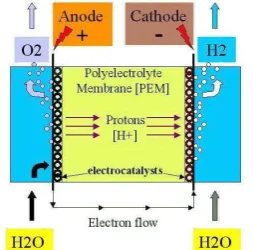
Hydrogen is produced by decomposition of water into hydrogen and oxygen by passing an electric current between two electrodes separated by aqueous electrolyte. Alkaline electrolyzers and polymer electrolyte membrane, PEM, are the two main types of electrolyzers, which are well developed [10]. PEM electrolyzer use a solid plastic material as an electrolyte. Figure 1 illustrates working principle of a PEM electrolyzer.
Fig. 1. Working principle of a PEM electrolyzer.
Water reacts at the anode to form oxygen, electrons, and positively charged hydrogen ions (protons). The electrons flow through external circuit to the cathode. The hydrogen ions move across the PEM to the cathode, where they recombine with the electrons to form hydrogen gas.
The total reaction for water decomposition is:
H2O + electrical energy Æ H2 + ½ O2, (1)
while main electrochemical reactions occurring at the two electrodes of electrolyzers are:
at anode
2H2O Æ O2 + 4H+ + 4e– , (2)
at cathode
4H+ + 4e–Æ 2H2 (3)
The global reaction is the addition of both electrochemical reaction plus 237.14 kJ/mol of energy that are required for the reaction to develop.
PEM electrolyzers are relatively new technology compared to the alkaline electrolyzers. Efficiency factors of PEM electrolyzers up to 94% are predicted, but this is only theoretical at this time. Today, the efficiency factors for PEM electrolyzers are lower than for the best alkaline electrolyzers. PEM electrolyzers function very well with renewable energy systems where the amount of electricity varies greatly.
C. Fuel Cell
When hydrogen is burned, there is a reaction between the oxygen and hydrogen which results in water, while energy is released in form of heat. In a fuel cell, the process is split in two. The two processes take place on each respective side of the electrolyte which keeps the gases separated, but which transports ions. The negatively charged electrons move in an outer electrical circuit. With this apparatus a portion of chemical energy is converted directly to electric energy. Theoretically, 83% of the energy can be generated into electricity. In reality, the efficiency is lower, but compared to traditional technology, the fuel cell is very efficient.
A fuel cell is, in principle, quite like the cell in a normal battery. The most important difference is that, while battery runs out of power eventually because the energy stored in them is exhausted, fuel cell continues to produce electricity as long as there is a supply of fuel.
There are several types of fuel cells with different characteristics and uses. They are usually classified according to the electrolyte that is used i.e. alkaline (AFC), proton exchange membrane (PEMFC), phosphoric acid (PAFC), molten carbonate (MCFC), solid oxide (SOFC), etc. The working principle of PEMFC is illustrated in Figure 2.
Fig. 2. Working principle of a PEM fuel cell.
turning into water. The electrolyte is the proton exchange membrane. This is a plastic (polymer) which is specially treated to be able to conduct positively charged ions (protons). The membrane stops the electrons from crossing over. The catalyst is a material which makes the reactions at the electrodes occur more rapidly, but which in itself does not participate in the reactions. The most common catalyst is platinum. Platinum is pulverized and evenly distributed around small carbon particles, in order to use the least amount of platinum and to create the greatest surface area possible. In addition to these four elements, a conducting plate or wire providing electrical contact between the electrodes is needed.
A PEM fuel cell operates by putting a hydrogen molecule in contact with the platinum catalyst, splitting it into two hydrogen ions (protons) and two electrons. The electrons are conducted by the electrode to the external circuit where they can power electrical equipments. They are then fed onward to the cathode where oxygen from the air splits into two oxygen atoms when it comes in contact with the catalyst. Two hydrogen ions combine with one oxygen atom and two electrons from the conductor to create a water molecule. The reaction in a fuel cell produces only about 0.7 volts, so several fuel cells are connected in a series to attain a functional level of output. Fuel cells connected together are called a fuel cell stack.
D. Storage of Hydrogen
Hydrogen is a substance with high energy content compared to its weight. This is the reason that hydrogen is naturally the first choice in space travel and very well suited for air travel. On the other hand, the energy content compared to volume is rather low. This poses greater challenges with respect to storage compared to storage of gasoline which is liquid. Basically there are three options i.e. hydrogen may be compressed and stored in a pressure tank, hydrogen may be cooled to a liquid state and kept cold in a properly insulated tank, and last option, hydrogen may be stored in a solid compound.
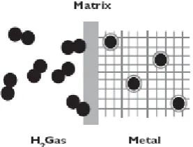
Certain metals and metal alloys have the ability to absorb hydrogen under moderate pressure and temperature, creating hydrides. Hydride is a compound which contains hydrogen and one or more other elements. A metal hydride tank contains, in addition to a heat manipulation system, granular metal which absorbs the hydrogen like a sponge absorbs water. The heat system draws heat away when hydrogen is filled into the tank, and applies heat when the hydrogen is taken out the tank. The hydrogen is released from the metal hydride when heat is applied. A metal hydride tank is considered to be a very safe fuel system in the event of a collision because the loss of pressure in a punctured tank will cool down the metal hydride, which will then cease to release hydrogen. Figure 3 illustrates mechanism of packing hydrogen gas in form of hydrides.
Fig. 3. Hydrogen gas in form of metal hydrides.
Hydrogen gas moves in toward the interface. There the hydrogen molecule is split into hydrogen atoms which are absorbed by the metal, whereby hydrogen is stored in the metallic matrix.
III. MATERIAL AND METHOD
Two solar modules of 50 watts peak output each were used. The module integrated by 36 monocrystalline silicon photovoltaic is product of Sunrise Solartech Co., Ltd. Based on the technical sheet, the module gives about 17.4 V maximum output voltage with 2.88 A photocurrent.
The electrolyzer used at the present study is a commercial product of Horizon Fuel Cell Technologies Ltd., namely Hydrofill. It is a high-performance water-based PEM electrolyzer system, from which water is extracted. Hydrofill is also designed to refill solid hydrogen cartridges. Using 60 W DC power, Hydrofill is able to produce pure hydrogen gas with maximum flow rate at 170 mL/min.
To generate electricity from hydrogen fuel, a commercial product of Horizon Fuel Cell Technologies Ltd., namely H-20 was used. The H-20 is an air-cooled, self-humidified PEM fuel cell system that uses hydrogen as fuel cell and oxygen in the free air as oxidant. It consists of 13 cells that can generate power up to 20 W with rated performance 7.8 V at 2.6 A.
The extracted hydrogen gas is stored in special solid hydrogen cartridge designed by Horizon Fuel Cell Technologies Ltd., namely Hydrostick. It is made from metal alloys and specially designed to be refilled with Hydrofill. With the dimension not bigger than AA-sized battery, it can store 10 L hydrogen gas in solid form.
Fig. 4. Experiment setup incorporating solar module, electrolyzer, fuel cell, and hydrogen storage
The power output of these solar modules, with 0.34 square meters each, were measured in sunlight to determine their output and efficiency. A single resistive load was used to evaluate peak output power i.e. 50 watts at 6 ȍ. The output of these solar modules was measured every 20 minutes from 8:00 AM to 4:00 PM. The resistive load was then replaced with loaded DC-DC converter to evaluate its daylight power output performance when it is powered by solar modules.
Regarding the electrolyzer, an experiment was conducted to evaluate power consumption during cartridge filling. The time required to fill up the cartridge with hydrogen gas was also noted. The volume of the distilled water and weight of the cartridge were also measured prior to and after the filling. The average power consumption during filling and amount of produced hydrogen then can be used to determine electrolyzer’s energy efficiency.
After the cartridge fully charged, it was plugged into fuel cell through a pressure regulator to energize it. A various resistive load was used to determine current-voltage characteristic and power curve of fuel cell. In a similar manner to electrolyzer, the efficiency of fuel cell at certain load was evaluated. The performance with regard to time was also evaluated to estimate the operation time of the fuel cell and fully-charged Hydrostick when running with about 10 watts power consumption.
IV. RESULT AND DISCUSSION
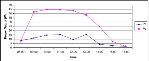
The output of these solar modules measured from 8:00 AM to 4:00 PM is illustrated in Figure 5.
0
08.00 09.00 10.00 11.00 12.00 13.00 14.00 15.00 16.00
Time
Fig. 5. Output power of solar modules in single and parallel configuration.
Firstly, only power output from single solar panel was measured. It was discovered that it reached a maximum power of 17 watts at 15 volts and 2.6 amperes. The two solar modules were then connected in parallel based on the theory that such configuration gives higher output power. As the result, the maximum power increased to 51 watts at 17.4 volts and 2.95 amperes. The maximum power point of single solar panel when it was exposed to direct sunlight is 50 watts at 17.4 volts and 2.88 amperes. The efficiency of the solar panel is based on the fact that 100% efficiency is defined as 1 kilowatt of solar radiation that 1 square meter of earth intercepts in 1 hour. If the solar panel has an area of 0.33 square meter and 50 watts output, then its efficiency is about 15%.
The resistive load of 6 ȍ was then replaced with DC-DC
converter based on LM338 from National Semiconductor. The converter was configured to give output voltage of 9 volts with maximum current of 5 amperes. In this experiment, solar modules exposed to solar radiation from 9:00 AM to 2:00 PM.
With 3 ȍ load connected to the output terminal of the
converter, the output voltage was 8.84 volts and the current drawn was 2.97 amperes, corresponding to a 26.28 watts power output.
The power consumption during electrolysis process and hydrogen gas filling was monitored and presented in Figure 6.
0
Fig. 6. Power consumption during electrolysis and filling.
The time required to fully charge a cartridge was approximately 150 minutes with power consumption 24 watts in average. The volume of water filled in the tank was 400 milliliters, at the end of the electrolysis there were 390 milliliters water remaining. The empty cartridge weighed 93 grams while the full cartridge (10 liters) weighed 94 grams. This is considered normal since the hydrogen atom has relative mass density of 0.09 grams/liter. The hydrogen production rate was then approximately 70 milliliters per minute. The energy efficiency of electrolyzer then can be expressed as follow
2 0
of the electrolytic cell, and the diffusion losses of the gases within the cell.
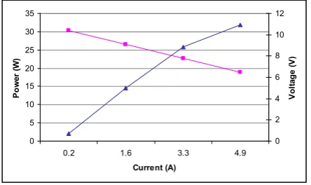
In the fuel cell the chemical energy of the hydrogen is converted to electrical energy. Figure 7 shows the performance of the fuel cell indicated by current-voltage characteristic and power curve.
Fig. 7. Fuel cell performance curves
The current at which the fuel cell exhibits the greatest power output is clearly evident from the power curve. Maximum power arises at about 4.9 amperes which corresponds to a load
resistance of 1.5 ȍ. The global power output under hydrogen
and oxygen saturation conditions is 2.8 amperes and 23.5 watts evaluated at 8 volts. In order to determine energy efficiency at
certain load, a fixed value load of 6 ȍ was connected to the
fuel cell output. During 10 minutes of experimentation, the average output voltage and current was 7.51 volts and 1.3 amperes, corresponding to a 9.8 watts power output. With the consumed hydrogen of 1.5 liters, the energy efficiency can be calculated using formula as follow
2
J/m3. The current energy efficiency deduced for the load of 6 ȍ was up to 36%. This means that 36% of the energy stored in the hydrogen gas used to operate fuel cell is outputted as electrical energy. The fuel cell also releases heat. If not utilized this heat is regarded as wasted energy. This limits the efficiency from the outset. Voltage losses, which also manifested as heat, further reduce the efficiency. Similar to electrolyzer, the efficiency of the fuel cell is heavily dependent on the power level. If the load has a high electrical resistance, although the efficiency of the cell is high, it will only operate under part load. Supplied with 10 liters of hydrogen gas and
operated under 6 ȍ load the running time of fuel cell was
approximately 40 minutes with average power output of 9.8 watts.
Figure 8 shows the picture of the fuel cell which the hydrogen gas supplied from the Hydrostick and oxygen gas from ambient air. The fuel cell also incorporates control unit, purging valve, and cooling fan.
Fig. 8. Fuel cell connected to a load.
V. CONCLUSION AND FUTURE WORK
In this paper, a clean electrical energy generation based on solar-hydrogen fuel cell system is demonstrated and evaluated. The system consists of two solar modules, DC-DC converter, electrolyzer, fuel cell, and hydrogen storage. The water electrolyzer with the help of solar modules converts water to hydrogen and store it in solid form. The fuel cell runs with the same hydrogen, converting it back to water and simultaneously electrical energy.
Two solar modules of 50 watts peak output each are used to convert energy from solar radiation to electrical energy. Single solar module can give maximum power output of 17 watts while the parallel configuration can give maximum power output of 51 watts. The efficiency of the solar panel is about 15%. Combined with DC-DC converter, they can produce power output of 26.28 watts with relatively constant output voltage of 8.84 volts from 9:00 AM to 2:00 PM.
The electrolyzer requires approximately 150 minutes with 24 watts electrical power extracting 10 liters hydrogen gas from distilled water and storing it into cartridge. After production of 10 liters hydrogen gas, the volume of distilled water is reduced by about 10 milliliters while the weight of the cartridge is raised by about 1 gram. With 24 watts electrical power supply, the hydrogen gas production rate is 70 milliliters per minute. The electrolyzer’s energy efficiency is up to 75%. The power supply for electrolyzer may be replaced by solar modules described previously since they can provide adequate electrical power for a period longer than required by electrolyzer.
The fuel cell can utilize hydrogen gas stored in the cartridge as fuel and oxygen in the ambient air as oxidant to produce electricity. The global power output under hydrogen and oxygen saturation conditions is 2.8 amperes and 23.5 watts
evaluated at 8 volts. The energy efficiency at 6 ȍ can reach
36%. A cartridge containing 10 liters of solid hydrogen can support the fuel cell running at 9.8 watts for approximately 40 minutes.
decomposition can be obtained from renewable fuel source, in this case solar radiation. These advantages make solar-hydrogen fuel cell technology promising sustainable electrical energy source in the near future.
The future work for this study involves development of a power management system to control and monitor energy production and consumption. The electrical energy generator system along with its power management system will also be implemented in a model house.
ACKNOWLEDGMENT
This work was fully supported by Hibah Bersaing 2010 grant from the Ministry of National Education. The authors thank staff members at the Department of Electronics and Computer Engineering at the Satya Wacana Christian University.
REFERENCES
[1] T.N. Verizoglu and S. Sahin, “21st Century’s energy: Hydrogen energy
system,”International Journal of Energy Conversion and Management, vol. 29, pp. 1820-1831, Feb. 2008.
[2] F. Orecchini, A. Santiangeli, and A.D. Era,” A Technological solution for everywhere energy supply with sun, hydrogen, and fuel cells”,
International Journal of Fuel Science and Technology, vol. 3, pp. 75-82,
Feb. 2006.
[3] J. Nowotny, C.C. Sorrell, and L.R. Sheppard, T. Bak,” Solar hydrogen: Environmentally safe fuel for the future”, International Journal of
Hydrogen Energy, vol. 30, pp. 521-544, April 2005.
[4] F. Barbir, “PEM electrolysis for production of hydrogen from renewable energy sources,”Journal of Solar Energy Engineering, vol. 78, pp. 661-669, 2005.
[5] P.H. Aurora, J.J. Duffy, “Solar hydrogen fuel cell system modeling”, in Proc. ISES 2005, 2005, paper 16, p. 371-421.
[6] S.A. Grigoriev, V.I. Porembsky, V.N. Fateev, “Pure hydrogen production by electrolysis for hydrogen energy”, International Journal of Hydrogen
Energy, vol. 31, pp. 171-175, Feb. 2006.
[7] L. Barreto, A. Makihira, K. Riahi, “The hydrogen economy in the 21st
century: A sustainable development scenario” International Journal of
Hydrogen Energy, vol. 28, pp. 267-284, March. 2003.
[8] J.A. Duffie, W.A. Beckman, Solar Engineering of Thermal Processes, 3rd
edition, New Jersey, USA: John Wiley and Sons Inc., 2006.
[9] M. Ibrahim, “Solar energy and the use of hydrogen as an energy vector in Libya”, Ph.D. thesis, University of Manchester Institute of Science and Technology, Manchester, United Kingdom, 2003.
[10] W. Pyle, J. Healy, R. Cortez, “Solar hydrogen production by electrolysis”,