BAB II
PERHITUNGAN RENCANA GARIS (LINES PLAN)
A. PERHITUNGAN DASAR
A.1. Panjang Garis Air Muat (Lwl)
Lwl = Lpp + 2 % x Lpp
Lwl = 116,1 + 2 % x 116,1
Lwl = 118,42 m
A.2. Panjang Displacement (L.Displ)
L Displ = 0,5 x (Lwl + Lpp)
L Displ = 0,5 x (118,42 + 116,1)
L Displ = 117,26 m
A.3. Coefisien Midship (Cm) Formula Arkent Bont Shocker
Cm = 0,90 + 0,10 x Cb
Cm = 0,90 + 0,10 x 0,69
Cm = 0,98 Memenuhi Syarat kapal barang sedang
(Cm = 0,95 ~ 0,99)
A.4. Coefisien Prismatik (Cp) Formula Troast
Cp =
Cm Cb
Cp =
98 , 0
69 , 0
Cp = 0,704 Memenuhi Syarat kapal barang sedang
(Cp = 0,68 ~ 0,82)
A.5. Coefisien Garis Air (Cw) Formula Troast
Cw = 0,690,025
Cw = 0,805 Memenuhi Syarat kapal barang sedang
(Cw = 0,80 ~ 0,87)
A.6. Luas Garis Air (Awl)
Awl = Lwl x B x Cw (m2)
Awl = 118,42 x 19,00 x 0,805
Awl = 1811,23 m2
A.7. Luas Midship (Am)
Am = B x T x Cm (m2)
Am = 19,00 x 7,8 x 0,98
Am = 145,230 m2
A.8. Volume Displacement (C Displ)
V Displ = Lpp x B x T x Cb (m3)
V Displ = 116,1 x 19,00 x 7,80 x 0,69
V Displ = 11872,15 m2
A.9. Coefisien Prismatik Displacement (Cp Displ)
Cp Displ = (
Displ L
Lpp
. ) x Cp
Cp Displ = ) 26 , 117
1 , 116
( x 0,704
Cp Displ = 0,69
A.10.Displacement (D)
D = Vol Displ x
x m (Ton)Dimana :
= 1,025 Berat jenis air lautMaka :
D = 11872,15 x 1,025 x 1,004
D = 12217,62 Ton
B. MENENTUKAN LETAK LCB
B.1. Dengan menggunakan Cp Displacement pada grafik NSP pada Cp
Displacement = 0,685 didapat letak titik LCB (Longitudinal Centre
Bouyancy) = 0,52 % x L Displ. Dimana L Displ = 113,12 m.
Cp Displ = (
Displ L
Lpp
. ) x Cp
Cp Displ = (
9 , 109
1 , 116
) x 0,704
Cp Displ = 0,69
a. Letak LCB Displ menurut grafik NSP
LCB Displ = 1,5 % x L Displ
LCB Displ = 1,5 % x 116,10
LCB Displ = 1,758 m (Di depan midship Lpp)
b. Jarak midship () L Displ ke FP
Displ = 0,5 x L Displ Displ = 0,5 x 117,26 Displ = 58,63 m c. Jarak midship () Lpp ke FP
Lpp = 0,5 x Lpp Lpp = 0,5 x 116,10 Lpp = 58,05 m
d. Jarak antara midship () L Displ dengan midship () Lpp
= Displ - Lpp
= 58,63 – 58,05
e. Jarak antara LCB terhadap midship () Lpp
= 1,758 - 0,58
= 1,178 m (Di depan Lpp)
B.2. Menurut Diagram NSP Dengan Luas Tiap Station (Am) = 145,23 m2
ordinat %
% thd
AM FS Hasil FM HASIL
AP 0 0 1 0 -10 0
1 0.12 17.4276 4 69.7104 -9 -627.394 2 0.251 36.45273 2 72.90546 -8 -583.244 3 0.421 61.14183 4 244.5673 -7 -1711.97 4 0.701 101.8062 2 203.6125 -6 -1221.67 5 0.85 123.4455 4 493.782 -5 -2468.91 6 0.914 132.7402 2 265.4804 -4 -1061.92 7 0.95 137.9685 4 551.874 -3 -1655.62 8 0.978 142.0349 2 284.0699 -2 -568.14
9 1 145.23 4 580.92 -1 -580.92
10 1 145.23 2 290.46 0 0
2 = -10479.8
11 1 145.23 4 580.92 1 580.92
12 1 145.23 2 290.46 2 580.92
13 0.988 143.4872 4 573.949 3 1721.847 14 0.943 136.9519 2 273.9038 4 1095.615 15 0.842 122.2837 4 489.1346 5 2445.673 16 0.747 108.4868 2 216.9736 6 1301.842 17 0.546 79.29558 4 317.1823 7 2220.276 18 0.345 50.10435 2 100.2087 8 801.6696 19 0.131 19.02513 4 76.10052 9 684.9047
FP 0 0 1 0 10 0
1 = 5976.215 3 = 11433.67
a. h = 20 .Displ L
h = 20
26 , 117
h = 5,863 m
b. Volume Displacement
V Displ =
d. Koreksi prosentase penyimpangan LCB
=
e. Koreksi prosentase penyimpangan untuk volume Displ
=
B.3. Perhitungan prismatik depan (Qf) dan koefisien prismatik belakang
(Qa) berdasarkan label “Van Lamerent”.
Dimana :
Qf = Koefisien prismatik bagian depan midship Lpp
Qa = Koefisien prismatik bagian belakang midship Lpp
e = Perbandingan jarak LCB terhadap Lpp
= (
1 , 116
178 , 1
) x 100 %
= 1,014 %
Dengan rumus tersebut diatas dapat dihitung harga Qa dan Qf dengan
rumus berikut :
Qa = Qf = Cp (1,4 + Cp) x e
Dimana :
Qf = Cp + (1,40 + Cp) x e
= 0,704 + (1,40 + 0,704) x 0,001014
= 0,725
Qa = Cp - (1,40 + Cp) x e
= 0,704 - (1,40 + 0,704) x 0,001014
= 0,682
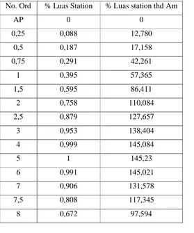
Tabel CSA lama menurut Van Lamerent (Lama) Am = 145,253 m2
No. Ord % Luas Station % Luas station thd Am
AP 0 0
0,25 0,088 12,780
0,5 0,187 17,158
0,75 0,291 42,261
1 0,395 57,365
1,5 0,595 86,411
2 0,758 110,084
2,5 0,879 127,657
3 0,953 138,404
4 0,999 145,084
5 1 145,23
6 0,991 145,021
7 0,906 131,578
7,5 0,808 117,345
8,5 0,504 73,195
9 0,324 47,054
9,25 0,234 33,983
9,5 0,148 21,494
9,75 0,069 10,020
FP 0 0
∑ = 1335,607
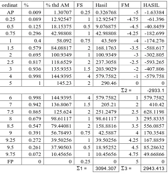
Tabel luas tiap section terhadap Am menurut Van Lamerent ( Baru )
Am = 145,23 m2
ordinat % % thd AM FS Hasil FM HASIL AP 0.009 1.30707 0.25 0.326768 -5 -1.63384 0.25 0.089 12.92547 1 12.92547 -4.75 -61.396 0.5 0.125 18.15375 0.5 9.076875 -4.5 -40.8459 0.75 0.296 42.98808 1 42.98808 -4.25 -182.699 1 0.4 58.092 0.75 43.569 -4 -174.276 1.5 0.579 84.08817 2 168.1763 -3.5 -588.617 2 0.695 100.9349 1 100.9349 -3 -302.805 2.5 0.817 118.6529 2 237.3058 -2.5 -593.265 3 0.936 135.9353 1.5 203.9029 -2 -407.806 4 0.998 144.9395 4 579.7582 -1 -579.758
5 1 145.23 2 290.46 0 0
2 = -2933.1 6 0.998 144.9395 4 579.7582 1 579.7582 7 0.942 136.8067 1.5 205.21 2 410.42 7.5 0.865 125.624 2 251.2479 2.5 628.1198 8 0.679 98.61117 1 98.61117 3 295.8335 8.5 0.547 79.44081 2 158.8816 3.5 556.0857 9 0.391 56.78493 0.75 42.5887 4 170.3548 9.25 0.272 39.50256 1 39.50256 4.25 167.8859 9.5 0.261 37.90503 0.5 18.95252 4.5 85.28632 9.75 0.072 10.45656 1 10.45656 4.75 49.66866
FP 0 0 0.25 0 5 0
a. h =
b. Volume Displacement pada Main Part
V Displ =
d. Perhitungan pada Cant Part
e =
2 Lpp -Lwl
=
2 1 , 116 42 , 118
= 1,16 m
e. Volume Cant Part
= 3 1
x e x 1
= 3 1
x 1,16 x 34,974
= 13,509 m3
LCB Cant Part terhadap () AP h. Volume Displacement total
B.4. Koreksi Hasil Perhitungan
a. Koreksi untuk Volume Displacement
= VolumeDisplacement Awal
Awal nt Displaceme Volume
Total Volume
. .
. .
. .
.
x 100 %
=
66 , 11888
15 , 11872 66
,
11888
x 100 %
= 0,13 % < 0,5 % (Memenuhi)
b. Koreksi untuk prosentase penyimpangan LCB
= Lpp
dshipLpp TerhadapMi
Total LCB Awal
LCB. . .
x 100 %
=
1 , 116
103 , 1 178 ,
1
x 100 %
C. RENCANA BENTUK GARIS AIR
C.1. Perhitungan Besarnya Sudut Masuk (α)
Untuk menghitung besarnya sudut masuk garis air berdasarkan Coefisien
Prismatik Depan ( Qf ).
Dimana :
Pada perhitungan penentuan letak LCB, Qf = 0,725
Dari grafik Latsiun sudut masuk = 12˚
Penyimpangan = ±3˚ dipakai + 3˚
Maka besarnya sudut masuk yang diperoleh = 12˚ + 3˚ = 15˚
C.2. Perhitungan Luas Bidang Garis Air
ord y=1/2 B fs hasil
AP 3.2 0.25 0.8
0.25 3.9 1 3.9
0.5 4.8 0.5 2.4
0.75 5.3 1 5.3
1 5.5 0.75 4.125
1.5 5.7 2 11.4
2 6.1 1 6.1
2.5 7 2 14
3 8.1 1.5 12.15
4 9.5 4 38
5 9.5 2 19
6 9.5 4 38
7 8.5 1.5 12.75
7.5 7.9 2 15.8
8 6.1 1 6.1
8.5 5.2 2 10.4
9 4.6 0.75 3.45
9.25 3.8 1 3.8
9.5 2.7 0.5 1.35
9.75 1.4 1 1.4
FP 0 0.25 0
Σ 1 232,952
a. Luas garis air pada Main Part
AWL MP = 2 x 3 1
x ( 10 Lpp
= 2 x 3
b. Rencana bentuk garis air pada Cant Part
D. PERHITUNGAN RADIUS BILGA Dimana : B = 19,00 m
H = 10,80 m
T = 7,80 m
A = Rise Of Floor
= 0,01 x B
= 0,01 x 19,00
= 0,19 m
R = Jari – jari Bilga
M = Titik pusat kelelngkungan bilga
D.1. Dalam Segitiga ABC
Tg α2 =
BC AB
=
181 , 0
050 , 9
α2 = 88,854º
α1 = 0,5 x (180 – a2) = 0,5 x (180 – 88,854)
= 0,5 x 91,146
= 45,575º
D.2. Perhitungan
a. Luas Trapesium ACED
= ½ B x 0,5 {T + (T - a )}
= 0,5 x 19,00 x 0,5 {7,80 + (7,80 - 0,181)}
= 73,197 m²
b. Luas AFHEDA
= ½ Luas Midship
= ½ x B x T x Cm
= ½ x 19,00 x 7,80 x 0,98
= 72,618 m²
c. Luas FGHCF
= 73,197 – 72,618
= 0,579 m²
d. Luas FCG
= ½ x Luas FGHCF
= ½ x 0,579
= 0,289 m²
e. Luas MFC
= ½ x MF x FC
= ½ x R x R Tg α1
Luas juring MFG = α1/360 x лR2
= Luas MFC - Luas juring MFG
= (0,5 R2Tgα1) – (α1/360 x лR2)
Jadi Luas ACED - Luas AFHEDA = Luas MFC - Luas juring MFG
73,197 – 72,618 = (0,5 R2 Tg α1) – (α1/360 x лR2)
0,579 = (0,5 R2 Tg 44,425) – (44,425/360x
3,14R2)
0,579 = 0,377 R2
R2 = 5,174
R = 2,273 m
E. MERENCANAKAN BENTUK BODY PLAN a. Merencanakan bentuk body plan adalah
Merencanakan atau membuat bentuk garis air lengkung padapotongan
ordinat.
b. Langkah – langkah
1) Membuat empat persegi panjang dengan sisi ½ B dan T
2) Pada garis air T diukurkan garis b yang besarnya = ½ luas station
dibagi T.
3) Dibuat persegi panjang ABCD
5) Dari titik E kita merencanakan bentuk station sedemikian sehingga
luas ODE = luas OAB letak titik O dari station – station harus
merupakan garis lengkung yang stream line.
6) Setelah bentuk station selesai dibuat, dilakukan pengecekan volume
displacement dari bentuk-bentuk station.
7) Kebenaran dari lengkung – lengkung dapat dicek dengan menggunakan
Planimeter.
E.1. Rencana Bentuk Body Plan
T = 7,80m
2 T = 15,6 m
ord L station Y=1/2 B B = L sta/2T
AP 3.5 2 0.224
0.25 11.548 3.9 0.740
0.5 26.527 4.8 1.700
0.75 32.421 5.3 2.078
1 50.041 5.5 3.208
1.5 74.112 5.7 4.751
2 97.845 6.1 6.272
2.5 114.961 7 7.369
3 136.746 8.1 8.766
4 143.25 9.5 9.183
5 145.23 9.5 9.310
6 145.23 9.5 9.310
7 134.056 8.5 8.593
7.5 119.255 7.9 7.645
8 102.412 6.1 6.565
C
E D
8.5 89.256 5.2 5.722
9 67.45 4.6 4.324
9.25 45.219 3.8 2.899
9.5 27.032 2.7 1.733
9.75 19.749 1.4 1.266
FP 0 0 0.000
E.2. Perhitungan Koreksi Volume Displacement Rencana Body Plan
Pada Main Part
no.ord L station Fs Hasil
AP 3.5 0.25 0.875
0.25 11.548 1 11.548 0.5 26.527 0.5 13.2635 0.75 32.421 1 32.421
1 50.041 0.75 37.53075 1.5 74.112 2 148.224
2 97.845 1 97.845
2.5 114.961 2 229.922 3 136.746 1.5 205.119
4 143.25 4 573
5 145.23 2 290.46
6 145.23 4 580.92
7 134.056 1.5 201.084 7.5 119.255 2 238.51
8 102.412 1 102.412 8.5 89.256 2 178.512 9 67.45 0.75 50.5875 9.25 45.219 1 45.219
9.5 27.032 0.5 13.516 9.75 19.749 1 19.749
FP 0 0.25 0
Σ 1 3070.718 a. Displasment perhitungan
= Lpp x B x T x Cb
= 116,1 x 19,00 x 7,80 x 0,69
= 11872,15 m3
b. Volume displasment main part
= 0,333 x 11,6 x 3070.718
= 11871,794 m3
c. Perhitungan Koreksi Volume Displacement Rencana Body Plan Pada
Cant Part
f. Volume Displacement perencanaan Total
= Vol Displ MP + Vol Displ CP
= 11871,794 + 4,055
= 11875,849 m3
g. Koreksi penyimpangan volume displacement body plan
F. PERHITUNGAN CHAMBER, SHEER DAN BANGUNAN ATAS F.1. Perhitungan Chamber
Chamber = 1/50 x B
= 1/50 x 19,00
= 0,38 m
F.2. Perhitungan Sheer Standart
a. Bagian Buritan (Belakang)
1) AP = 25 (Lpp/3 + 10)
= 25 (116,1/3 + 10)
= 1217,5 mm
2) 1/6 Lpp dari AP = 11,1 (Lpp/3 + 10)
= 11,1(116,1/3 + 10)
= 540,57 mm
3) 1/3 Lpp dari AP = 2,8 (Lpp/3 + 10)
= 2,8 (116,1/3 + 10)
= 136,36 mm
b. Bagian Midship (Tengan) = 0 m
c. Bagian Haluan (Depan)
1) FP = 50 (Lpp/3 + 10)
= 50 (116,1/3 + 10)
= 2435 mm
2) 1/6 Lpp dari FP = 22,2 (Lpp/3+10)
= 22,2 (116,1/3 + 10)
= 10081,14 mm
3) 1/3 Lpp dari FP = 5,6 (Lpp/3 + 10)
= 5,6 (116,1/3 + 10)
= 272,72 mm
F.3. Rencana Bangunan Atas (Menurut methode Varian)
a =
500
Lpp
+ 0,48
= 500
1 , 116
+ 0,48
= 0,704 m
Jarak gading besar
= 4 x Jarak gading
= 4 x 0,6
= 2,4 m
Jarak Gading Besar = 4 x 0,6 = 2,4 M
Jarak Gading Mayor = 187 x 0,6 = 112,2 M
Jarak gading Minor = 3 x 0.5 = 1,5 M +
Jumlah = 116,10 M
Jarak gading :
AP – frame 191 = 0,6 x 191 = 114,6 m
frame 191 – frame FP = 0,5 x 3 = 1,5 m +
Lpp = 116,1 m
Jumlah jarak gading keseluruhan = 194 gading
b. Poop Deck (Geladak Kimbul)
Panjang Poop Deck (20 % - 30 %) Lpp dari AP
Panjang = 20 % x Lpp
= 0,20 x 116,1
= 23,22 m, direncanakan 23,4 m dari AP
Rencana letak gading
39 jarak gading x 0,6 = 23,4 m
39 jarak gading dari AP = 23,4 m
Tinggi poop deck 2,0 s/d 2,4 m, direncanakan 2,2 m dari main deck
c. Fore Castle Deck (Deck Akil)
Panjang fore castle deck (10% - 15 %) Lpp dari FP
Panjang = 10 % x Lpp
= 10 % x 116
= 11,6 m, direncanakan 11,7 m dari FP
Rencana letak gading
17 jarak gading x 0,6 = 10,2 m
3 jarak gading x 0,5 = 1,5 m +
19 jarak gading dari FP = 11,7 m dari FP
Tinggi deck akil 2,0 s/d 2,4 m diambil 2,2 m dari main deck.
G. PERHITUNGAN UKURAN DAUN KEMUDI Perhitungan ukuran daun kemudi
Perhitungan kemudi menurut BKI 2006 Vol II (hal 14 Sec.14-1. A.3)
A = C1 x C2 x C3 x C4 x
100 T x L x 1,75
(m2)
Dimana :
A = Luas daun kemudi dalam m2
L = Panjang kapal = 116,10 m
T = Sarat kapal = 7,80 m
C1 = Faktor untuk type kapal = 1
C2 = Faktor untuk type kemudi = 0.7
C3 = Faktor untuk profil kemudi = 0,8
C4 = Faktor untuk rancangan type kemudi = 1,5 untuk kemudi dengan jet
propeller.
Jadi :
A = 1,0 x 0,7 x 0,8 x 1,5 x
100 80 , 7 10 , 116 75 ,
1 x x
(m2)
= 13,3 m2
=
G.1. Ukuran Daun Kemudi
A = h x b
Seluruh luas kemudi (buku perlengkapan kapal hal 52)
A’ = 20 % x A
= 20 % x 13,5
Lebar bagian yang dibalansir pada potongan sembarang horizontal < 35
% dari lebar sayap kemudi (buku perlengkapan kapal hal 52). Di ambil
35 %
b’ = 30 % x b
= 30 % x 2,7
= 0,8 m
Dari ukuran diatas dapat diambil ukuran daun kemudi :
Luas daun kemudi (A) = 13 m2
Luas bagian balansir (A’) = 3,9 m2
Tinggi daun kemudi (h’) = 5 m
Lebar daun kemudi (b’) = 2,7 m
Lebar bagian balansir = 0,8 m
G.2. Perhitungan Gaya Kemudi
Menurut BKI 2006 Vol II (hal 14-3 Sec B.1.1) tentang gaya kemudi
adalah :
Cr = 132 x A x V2 x k1 x k2 x k3 x kt (N)
Dimana :
A = Luas daun kemudi = 13 m²
V = Kecepatan dinas kapal = 15,4 Knots
k1 = Koefisien yang bergantung pada aspek ratio (Δ) Δ = h²/A
= (5)²/13
= 1,88
k1 = 3
2
= 3
2 88 ,
1
, dimana besarnya Δ tidak boleh lebih dari 2
= 1,29
k3 = 1,15 untuk kemudi dibelakang propeller
kt = 1,0 (normal)
Jadi :
Cr = 132 x 13 x (15,4)2 x 1,9 x 1,4 x 1,15 x 1,0
= 867305,467 N
H. PERHITUNGAN SEPATU KEMUDI H.1. Modulus Penampang Sepatu Kemudi
Modulus penampang dari sepatu kemudi terhadap sumbu Z, menurut BKI
2006 Vol II hal 13-3
Dimana :
Bl = Gaya kemudi dalam resultan
B1 = Cr /2
Cr = Gaya Kemudi
Cr = 867305,467 N
B1 = 2 867305,467
= 433652,73 N
X = Jarak masing-masing irisan penampang yang bersangkutan terhadap
sumbu kemudi
X = 0,5 x L50 (X minimum)
L50 = L (X maximum)
Dimana :
L50 = 3 10 Pr x
Cr
Dimana Pr = 3
10 x 10 L
Cr
L10 = Tinggi daun kemudi h = 5 m
Pr = 3
x10 5
867305,467
L50 = 3
10 Pr x
Cr
L50 = 3
x10 177,214
867305,467
= 4,89 m, di ambil 2,7 m
X min = 0,5 x L50
= 0,5 x 2,7
= 1,35 m
k = Faktor bahan = 1,0
Wz = 80
k x X x B1
=
80
0 , 1 35 , 1
433652,73x x
= 7317,88 cm3
Wy = 1/3 x Wz
= 1/3 x 7317,88
= 1607,452 cm3
H.2. Perencanaan profil sepatu kemudi dengan plat dengan ukuran sebagai
berikut :
Tinggi (h) = 30 cm = 300 mm
Tebal (s) = 2 x 3 = 6 cm = 60 mm
Lebar (b) = 300 mm
No b h f = b x h a F x a² Iz = 1/12 x b x h³
I 30 6 180 0 0 540
II 6 26 156 12 22464 8788
III 6 26 156 0 0 8788
IV 6 26 156 12 22464 8788
V 30 6 180 0 0 540
Σ1= 44928 Σ2= 27444
IZ = 1 + 2
Harga Wz yang akan direncanakan
Koreksi perhitungan Wz
= 100%
I. STERN CLEARANCE
Ukuran diameter propeller ideal adalah (0,6 – 0,7) T
Dimana T = Sarat kapal
Diambil 0,6 x T
D Propeller Ideal adalah
= 0,6 x T
= 0,6 x 7,8
= 4,68 m
R (Jari – jari Propeller)
= 0,5 x D Propeller
= 0,5 x 4,08
= 2,34 m
Diameter Boss Propeller
= 1/6 x D
= 1/6 x 4,68
Menurut konstruksi lambung BKI, untuk kapal baling - baling tunggal jarak
minimal antara baling – baling dengan linggi buritan menurut aturan
konstruksi BKI 2006 Vol II Sec 13 – 1 adalah sebagai berikut :
a. 0,1 x D = 0,1 x 4,68
= 0,468 m
b. 0,09 x D = 0,09 x 4,68
= 0,4212 m
c. 0,17 x D = 0,17 x 4,68
= 0,7956 m
d. 0,15 x D = 0,15 x 4,68
= 0,702 m
e. 0,18 x D = 0,18 x 4,68
= 0,8424 m
f. 0,04 x D = 0,04 x 4,68
= 0,187 m
g. 2” – 3” Diambil 2,5” = 2,5 x 25,4
= 63,5 mm
Jarak poros propeller dengan Base Line adalah :
= R Propeller + f + Tinggi sepatu kemudi
= 3,9 + 0,1872 + 0,29