Lubrication
Proper lubrication and maintenance are essential for long bearing life. An adequate supply of clean lubricant must be present at all times to prevent damaging, metal-to-metal contact.
Twin City Fan Companies’ experience has shown that grease is the best type of lubricant for fan applications. For ball and spherical roller bearings a NLGI Grade 2 or 3 grease is recommended. Special high temperature greases are rec-ommended if the bearing temperature exceeds 160°F.
Avoid mixing greases with different bases. This can cause hardening of the grease and inadequate lubrication. The grease used at the factory is a lithium-based grease. When using a grease constructed with a different base (such as sodium or a synthetic base), keep adding the new grease until all of the lithium based grease purges out of the bear-ing.
Fans are shipped with labels on them showing the relu-brication schedule for normal operating conditions. If the operating condition is relatively clean and at ambient tem-perature, use the relubrication interval shown on the sticker as a starting point. Frequently, however, operating condi-tions are dirty or humid and require more frequent relubrica-tion. If there is high moisture, high temperature, or if the shaft is in the vertical position, start out relubricating twice as often as shown on the sticker and adjust the interval as required. The best way to see if a relubrication interval is adequate is to check the condition of the grease purged from the bearing when adding new grease. If darkened and badly oxidized grease purges, relubricate more frequently. If the purged grease looks about the same as new grease, a longer interval may work.
High ambient temperatures can make bearing and lubri-cant selection difficult. The viscosity of the oil contained in the grease is the property that prevents metal-to-metal con-tact. With most common lubricants, the viscosity starts to fall at temperatures over 200°F. Because the temperature inside the bearing is always higher than the ambient tem-perature, bearing and lubricant selection is difficult if the ambient temperature rises over 125°F. External means of cooling the bearing may be required in these situations.
Static or circulating oil should only be used with split pil-low block bearings on high speed or high temperature appli-cations where grease is unsuitable. Oil lubricated bearings require more rigorous maintenance. High oil levels can pre-vent the bearing from pre-venting the air inside the bearing as it heats up. The built-up pressure can blow all of the oil out of the bearing in only a few minutes. Low oil levels do not pro-vide adequate lubrication. If sight gauges are used to mon-itor the oil level they must be adjusted to read properly. Since the indicated level changes when the fan is turned on,
it is best to check the oil levels when the fan is off. If this is not possible, the proper level with the fan on must be marked on the level also. Oil can be blown out of bearings installed in the airstream, or near a non-sealed shaft hole. For this reason, Twin City Fan Companies does not recom-mend oil lubrication on arrangement 3 fans under any con-ditions.
Another advantage of grease is that it provides better protection for the bearing against corrosion during storage and other idle periods.
Installation Effects on Bearing Life
The belt drives used on fans have a large effect on bearing life. The combination of the sheaves selected and their mountings can make the difference between having a bear-ing last its expected life and havbear-ing it fail prematurely.Figure 1 shows a typical fan selected to use a sheave with a six inch diameter on the fan shaft. With the sheave mounted at the end of the shaft, as far away from the bear-ing as possible, the L-10 life calculates to be 32,000 hours. (See ED-1200 for an explanation of L-10 life.) By moving the sheave 1.25" closer to the bearing, the life is increased to 40,000 hours. When the sheave is moved in another 1.25" so that it is as close to the bearing as possible, the life increases to 50,000 hours. The lesson learned by this exam-ple is to maximize bearing life by mounting the sheave as close to the bearing as possible.
Most belt drives are selected using computer programs. The user puts in the information and the computer selects several sheave and belt combinations that will work, and usually highlights the least expensive. But the combination selected has a significant effect on bearing life. Large sheaves result in less belt pull and longer bearing life. Figure 2 shows the L-10 life for different fan sheave diameters. All of them are viable drive selections. The L-10 life varies from 19,000 hours with a 4.2 inch diameter sheave, to 90,000 hours with an 8.2 inch diameter sheave. Avoid the selections with the smallest sheave sizes. They are probably not the least expensive anyway since they require more belts. The best drive selection is one with a reasonable sheave size and moderate cost.
Fan orientation affects bearing life. A fan designed to operate with its shaft positioned horizontally will have a lower bearing life when positioned with a vertical shaft. This is due to the additional thrust loads put on the bearings from the shaft and impeller weight. Figure 3 shows an example. An axial fan designed for horizontal duty has an L-10 life of 49,800 hours. Tipping the fan so that the shaft is vertical lowers the bearing life to an unacceptable level of 13,400 hours. If a fan is to operate with a vertical shaft, make sure to order it for this orientation.
Fan Bearing
Maintenance & Troubleshooting
©2000 Twin City Fan Companies, Ltd.
E
NGINEERING
D
ATA
ED-1300
Information and Recommendations for the Engineer
Bearing Failures and Their Causes
The L-10 life discussed earlier is an estimate of the fatigue life of a bearing. However, there are many other factors that determine how long a bearing lasts. Figure 4 shows the results of one study that looked at the reasons for bearing failure. What is interesting about this study is that it shows that normal fatigue is not the normal cause of bearing fail-ure, since only 34% of the bearings failed this way. Half of the bearing failures were due to either inadequate lubrica-tion or contaminalubrica-tion. Other sources list fatigue to be the cause of only 10% of bearing failures.Figure 4. Bearing Failure Causes
36% - Inadequate Lubrication 34% - Normal Fatigue 14% - Contamination
Source: Rolling Bearing Digest, 1985
If bearings that are failing can be taken out of service before they are completely destroyed, they can reveal infor-mation about the cause of failure. Different modes of failure leave unique evidence in the bearing components. The rest of this article shows how the more common types of fan bearing failures affect bearing components.
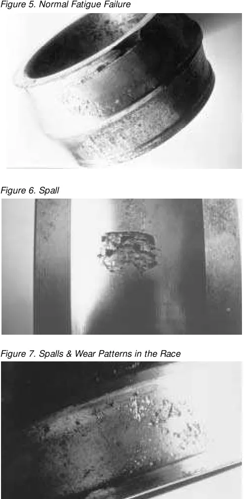
Figure 5 shows an inner race that has had a normal fatigue failure. The repeated loading and unloading of the race every time a roller passes eventually causes micro-scopic fatigue cracks to form under the surface.
In time, these cracks grow to the point where small por-tions of the surface flake off. This process is called “spalling” and the flaws left in the surface are called “spalls.” With continued operation, the spalls grow until the bear-ing becomes noticeably noisy. Figure 6 shows an inner race that has a severe spall. In addition to being noisy, it is also likely that this bearing would show high levels of vibration. The time required for the spalling to cause catastrophic bearing failure will vary with the load on the bearing and its speed. Usually the bearing will run for a while after it becomes noisy, but once noise is heard, prepare to have the bearing changed before it fails suddenly.
Inadequate lubrication can lead to spalling as seen in Figure 7. This bearing also shows signs of excessive wear due to inadequate lubrication. The rollers have worn a very deep wear pattern in the race.
Inadequate lubrication does not mean that there is no lubrication, only that the lubricant is not preventing
metal-3.5
POSITION L-10 LIFE
A 32,000 HRS. 1400 RPM, 15 HP MOTOR
111⁄16SHAFT
HEAVY DUTY BALL BEARINGS
AS SOLD AS INSTALLED
L-10 = 49,800 HRS. L-10 = 13,400 HOURS
Figure 1. Effect of Sheave Location on Bearing Life
Figure 2. Effect of Sheave Diameter on Bearing Life
Figure 3. Effect of Shaft Position on Bearing Life
Figure 5. Normal Fatigue Failure
Figure 6. Spall
to-metal contact. This can be due to adding an insufficient amount of lubricant when relubricating, too long of a period between relubrications, using dirty lubricant, or using a lubricant that does not have the viscosity needed to main-tain an oil film between the parts.
Figure 8 shows the progressive failure of a bearing due to inadequate lubrication. At first there are traces of waviness, or a slight roughening of the race. With time small cracks develop, which lead to a modest amount of spalls and even-tually the severe amount of spalling shown on the lower right.
Figure 8. Progressive Failure of a Bearing Due to Inadequate Lubrication
If the bearings continue to operate with inadequate lubri-cation, the evidence that shows this to be the mode of fail-ure becomes destroyed. Notice how the spherical bearing rollers shown in Figure 9 become damaged with continued operation.
Figure 9. Damaged Spherical Bearing Rollers
If the bearing had been taken out of operation when the roller was in the condition shown on the left, it would be possible to determine the cause of failure. By the time the bearing completely failed, it had run so hot that the steel softened and the bearing became deformed. At this point it is impossible to tell what caused the initial failure. If you are having unexplained bearing failures, it is best to take the bearing out of service when you first notice noisy, hot, or vibrating operation. The evidence showing the initial cause of failure is probably still visible, and it will give you an idea as to what action to take to prevent additional failures.
Under the right conditions the heat generated by metal-to-metal contact causes the two surfaces to adhere for an instant. Small portions tear out from one surface and adhere to the other surface. This is “smearing” and is shown in Figure 10.
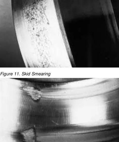
“Skid smearing,” shown in Figure 11, occurs on lightly loaded bearings. As the rollers come around and enter the lower half of the bearing, they go from being unloaded to being under load. With the light load it takes them some dis-tance to roll properly, and they skid against the race causing smearing.
Inadequate lubrication can sometimes cause the bearing surfaces to become highly polished as Figure 12 shows.
Even though the surface looks nice, this is an indication of trouble. With continued operation the surface will change to a frosty appearance and eventually spall.
Material that flakes out of spalls and other contaminants from other sources such as dirty grease or worn seals dents the races when caught between the rollers and races. Figure 13 shows an inner race with severe particle denting. Figure 7 also shows signs of particle denting. Each dent is a stress concentrator, which increases the stress in the area around the dent and accelerates the fatigue failure process.
Keeping moisture out of bearings is necessary to achieve long life. Figure 14 shows a bearing severely damaged from water corrosion. This much damage was probably due to seal failure, possibly in a “wash down” environment. High moisture applications require the use of grease that has rust inhibiting properties. Frequent relubrication is necessary, to insure that all bearing surfaces are coated with a protective layer of grease and that the rust inhibitors are replenished.
Figure 10. Smearing
Figure 11. Skid Smearing
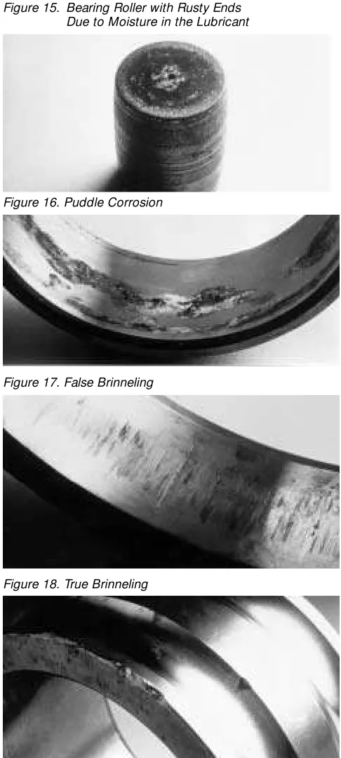
Figure 15 shows a spherical roller bearing roller that has rusty ends from moisture in the lubricant.
Water from condensation causes corrosion in idle fans. This is particularly true for fans in high moisture areas, located outdoors, or improperly stored outdoors. Figure 16 shows an outer race damaged by puddle corrosion. Moisture or dew condensing in the bearing settles to the bottom of the race in puddles and causes rusting. Twin City Fan Companies packs ball and unit roller bearings com-pletely full of grease prior to shipment. Split pillow block spherical roller bearings are shipped with the bearing insert packed full. This minimizes the chances of having puddle corrosion occur during shipment and storage. This practice covers all components with grease, and insures there are no pockets of air where water can condense. At startup the excess grease purges out of the bearing, which gets a little messy but is better than having a damaged bearing.
Figure 17 shows damage to an outer race from a bearing subjected to vibration while the unit is not rotating. Notice the even spacing of the marks, which correspond to the roller spacing. You can also see marks where the rollers came to rest in different locations. This type of damage, called “false brinnelling,” occurs when small portions of the race get rubbed away. The remaining area is ideal for start-ing fatigue, and the abrasive material rubbed off contami-nates the grease which accelerates bearing wear.
“True brinnelling” occurs when a bearing is subjected to impact and the rollers dent the races. Figures 18 and 19 show damage caused by improper mounting. Impact from hammering on the outer race or the bearing housing causes true brinnelling of the races. If it is necessary to tap on a bearing to get it into position, tap on the inner race so that the rolling elements do not carry the load. Dropping a bear-ing prior to mountbear-ing can also cause true brinnellbear-ing. Like false brinnelling, the marks are evenly spaced and the dam-age will eventually develop into spalls. Figure 20 shows spalls resulting from true brinnelling.
Mounting a bearing pillow block on a warped or crowned surface, or improperly shimming a pillow block can pinch the outer race. As seen in Figure 21, this causes two load zones on the outer race 180° apart.
As the rolling elements pass through the pinched area, the load between them and the races increases. If the sever-ity of the pinch is high, a drastic reduction in the life of the bearing will result.
Too much clearance between the bore of a bearing and the shaft, or too tight of a fit, can lead to bearing failures. Figure 22 shows the surface of a bearing bore that had too much clearance. The shaft turned in the bore, smearing the surface.
Insufficient tightening of the setscrews on a setscrew mounted bearing causes this type of failure. It can also be caused on a tapered adapter mounted bearing by not tightening the adapter lock nut enough. The damage to the surface resulted in a crack.
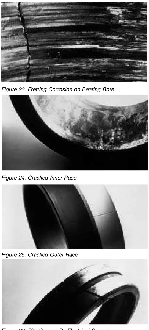
The bore of the bearing shown in Figure 23 shows signs
Figure 13. Severe Particle Denting Figure 14. Water Corrosion
Figure 15. Bearing Roller with Rusty Ends Due to Moisture in the Lubricant
Figure 16. Puddle Corrosion
Figure 17. False Brinneling
of serious fretting corrosion. Microscopic movement be-tween the shaft and the bore causes the rust colored patch-es to develop. Small amounts of fretting are common with setscrew mounted bearings and are not detrimental to bear-ing life. Advanced cases, caused by loose mountbear-ing, can lead to cracks.
Tightening the locknut of an adapter mounted bearing too much can crack the inner race as shown in Figure 24, or the outer race as shown in Figure 25.
This also occurs by exposing the bearing on a high tem-perature fan to excessive temtem-peratures. This easily happens when shutting down high temperature fans when they are hot, or by exposing them to high temperatures while idle.
Allowing electrical current to pass through a bearing can cause damage. Figure 26 shows a spherical roller with pits in its surface caused by electrical current. This type of dam-age commonly occurs when welding balance weights on a fan wheel with improper grounding. To avoid having the welding electrical current pass through the bearings, attach the grounding clamp to the wheel or shaft when adding bal-ance weights.
Figure 19. True Brinneling
Figure 22. Smearing on a Bearing Race
Figure 23. Fretting Corrosion on Bearing Bore
Figure 24. Cracked Inner Race
Figure 25. Cracked Outer Race
Figure 26. Pits Caused By Electrical Current Figure 20. Spalls Resulting from True Brinneling
Bearing Installation and Maintenance Guide, SKF USA Incorporated, King of Prussia, Pennsylvania, 1992 SKF General Catalog, SKF USA Incorporated, King of Prussia, Pennsylvania, 1991
Bearing Technical Journal, PTC Components Incorporated, Indianapolis, Indiana, 1982 Bearing Failure: Causes and Cures, The Barden Corporation, Danbury, Connecticut, 1992
Dodge Engineering Catalog, Volume 1.1R, Reliance Electric Industrial Company, Greenville, South Carolina, 1993 Sealmaster Bearing Products, Morse Industrial, Emerson Power Transmission Corporation, Ithaca, New York, 1988 Eugene R. Hafner, “Selecting Bearings for Fans and Blowers” Machine Design, April 29, 1990
Photographs in Figures 5 through 26 are courtesy of SKF USA Incorporated References
Summary
There are several different types of rolling element bearings used for fan applications. The best choice is the one that provides adequate L-10 life with reasonable cost. Proper
care during mounting, shipment, storage, and operation is required in order for the bearings to achieve the theoretical L-10 life they were selected for.
TM
AIR
MOVEMENT
ASSO CIA
TION AND
CONTR
O
L
INTERNATI ONA
L
®
R
MEMBE
I NTERNATI O NAL
F
A
N
DE SIG
N& MANUF ACT
U
R
IN
G