COMBINATION OF TLS POINT CLOUDS AND 3D DATA FROM KINECT V2 SENSOR
TO COMPLETE INDOOR MODELS
E. Lachat*, T. Landes, P. Grussenmeyer
Photogrammetry and Geomatics Group, ICube Laboratory UMR 7357, INSA Strasbourg, France (elise.lachat, tania.landes, pierre.grussenmeyer)@insa-strasbourg.fr
Commission V, WG V/4
KEY WORDS: Data combination, TLS point cloud, Kinect v2, Indoor 3D modeling, Building elements
ABSTRACT:
The combination of data coming from multiple sensors is more and more applied for remote sensing issues (multi-sensor imagery) but also in cultural heritage or robotics, since it often results in increased robustness and accuracy of the final data. In this paper, the reconstruction of building elements such as window frames or door jambs scanned thanks to a low cost 3D sensor (Kinect v2) is presented. Their combination within a global point cloud of an indoor scene acquired with a terrestrial laser scanner (TLS) is considered. If the added elements acquired with the Kinect sensor enable to reach a better level of detail of the final model, an adapted acquisition protocol may also provide several benefits as for example time gain. The paper aims at analyzing whether the two measurement techniques can be complementary in this context. The limitations encountered during the acquisition and reconstruction steps are also investigated.
* Corresponding author
1. INTRODUCTION
Combining data from various sensors is a wide but promising topic. Next to additional computations implied because of heterogeneous data handling, it enables to overcome the weaknesses of a kind of device thanks to the strengths of another one. The burning issue while considering data combination deals with the solution given to the registration of heterogeneous data. Even if data combination is common practice in fields such as remote sensing or robotics, only few references in the literature report on the creation of building models based on various datasets.
Most of the research works dealing with indoor modeling or more recently with as-built BIM (Building Information Modeling) creation make use of terrestrial laser scanners (TLS) to collect datasets in form of point clouds. As a matter of fact, laser scanning technologies enable to obtain a large amount of accurate 3D data. Despite these benefits, occlusions may occur in the produced point clouds because of the geometry of the scene, restricting the automation of the modeling process. Moreover, the acquisition process can be very time-consuming if a high level of detail (LoD) is required. To improve these aspects, this paper proposes an original combination of 3D data obtained with a Kinect v2 sensor, with a global TLS point cloud. The goal is to complete the building structural elements reconstructed based on TLS acquisitions with detail elements such as doors or windows reconstructed based on Kinect acquisitions. It will be interesting to analyze whether these geometrical primitives acquired with Kinect sensor can contribute to a better LoD of the final model.
Since indoor building modeling and data integration are wide research areas, some related works are first reported. Then the methodology developed in this paper is exposed. This goes
from the acquisition protocol which has to be adapted because of sensors specifications, to the processing chain applied for geometrical primitives reconstruction. Of course, the registration of both datasets is highlighted. After results presentation and their assessment, potential improvements not only about reconstruction but also about acquisition and registration are discussed.
2. RELATED WORKS
2.1 Modeling of openings to increase the level of detail
The creation of as-built BIM or HBIM (Historical BIM) is a quite recent and transversal topic, where many actors from various domains interact. Numerous research works report on the modeling issue. Methodologies based on automatic or semi-automatic segmentation of the point clouds are often considered for the purpose of first modeling steps (Macher et al., 2015). The segmentation results into structural primitives or subspaces, which can be floors or rooms. To be able to detect smaller elements (openings for instance), the knowledge of planes is a prerequisite. Often based on the RANSAC algorithm, this issue is settled by plane detection and segmentation (Thomson and Boehm, 2015 or Ochmann et al., 2015).
Once large primitives such as walls have been detected, the localization of openings can be determined from the laser scanner point clouds. Many approaches deal with the modeling of indoor spaces and their characteristics like for instance (Xiong et al., 2013). Barazzetti et al. (2015) study the construction of parametric objects based on point clouds for BIM completion. Considering more specifically the detection of windows, this can be made from terrestrial (Tuttas and Stilla, 2011) but also from sparse aerial datasets (Tuttas and Stilla,
2012). While for some projects such a model with opening locations may suffice, this is not the case for more complex analyzes concerning specific features of architecture. For the sake of completeness, further works are dedicated to addition of even more details into the model. Indeed, a good knowledge of the moldings geometry can be useful for actors such as architects or archaeologists in an as-built BIM or HBIM approach. In this context, Valero et al. (2011) deal with the modeling of moldings based on laser scanner 3D data. The moldings are reconstructed based on the creation of profile descriptors, which allow their recognition in the point clouds.
2.2 Multiple data integration photogrammetric 3D datasets are often combined in these approaches.
For 3D building model reconstruction, aerial or terrestrial laser scanner acquisitions can also be completed with photographs to improve the reconstruction process (Boehm et al., 2007). In the works of Vosselman (2002), the knowledge of ground plans is additionally used. But this is rather adapted to city scale where the considered areas are larger than only one building. It is worth noting that the literature dealing with the use of low cost sensor data to complete detailed building models is rather poor. In Henry et al. (2015) for example, a Kinect-style device is used alone to construct a 3D indoor model. Nevertheless, the use of data gathered from low cost sensors in combination with other kinds of data is rather standard in robotics. This is the case in many SLAM (Simultaneous Localization and Modeling) issues, where LiDAR data and/or RGB-D cameras are coupled to IMU (Inertial Measurement Unit) for the trajectory estimation (Huai et al., 2015).
2.3 Contribution of the paper
This paper reports on an original combination of data coming from two sensors using different technologies. The data acquired thanks to a low cost active sensor are used to complete indoor models reconstructed based on terrestrial laser scanner acquisitions. The main goal is to assess how complementary acquisitions. Besides, a lower point density enables a reduction of the volume of acquired data. This has a positive influence during processing and visualization of the data, but also for storage issue.
A last benefit to mention is the flexibility provided by the method. If small parts appear to be missing or occluded during data processing, it is possible to go back on site with only one handheld sensor such as Kinect. Thus a new measurement campaign with the laser scanner is avoided. This can also be interesting on building renovation sites, to facilitate the updating of the (existing) building model by scanning only new window frames for example.
3. ACQUISITION PROTOCOL
3.1 Sensors
To gather large scale information about the geometry and the volumetric aspect of the room, a laser scanner from FARO is used. The low cost device that has been chosen to complete the previous dataset is a Kinect for Windows v2 from Microsoft. Advantages of this sensor such as its low price and its capability of acquiring point clouds of small scenes in real-time can be mentioned. Moreover, an adapted calibration of this active sensor as well as quality assessment issues for 3D modeling of objects have already been investigated in (Lachat et al., 2015). Specifications about measurement principle and performance parameters of both sensors are listed in Table 1.
FARO Focus3D
Type of use Tripod mounted Tripod mounted or handheld
Table 1. Specifications of both sensors used
3.2 Places
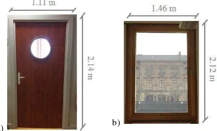
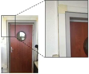
Because of the performance degradation observed for the Kinect sensor during outdoor acquisitions, the modeling approach exposed in this paper is limited to indoor environments. The acquisitions were carried out on a single room of about 90 m². This room contains several windows of identical geometry, as well as two doors (Figure 2).
a) b)
Figure 2. Pictures of door (a) and window (b) to reconstruct
3.3 Adapted protocol
3.3.1 Laser scanner acquisitions: To define the global volumetric aspect of the room, a point cloud of low density is sufficient. For this purpose, the laser scanner is used to perform 360° point clouds as in standard building acquisition protocol. In order to estimate which gain in terms of time could be
reached for such a standard room, two acquisitions were realized with different point spacing for the TLS scans. With the FARO Focus used, spatial sampling can vary from 1/1 for a very high density of points to 1/32 for a low density. The quality criterion proposed by this device was left to its default value of 4 during all acquisitions to avoid this parameter to have an influence on the acquisition time. Elapsed times and point spacing for different spatial samplings are listed in Table 3.
Spatial sampling
Point spacing (@ 10 m)
Scanning duration*
Number of points
1/1 1.5 mm > 1 hour ~ 699 millions
1/2 3 mm ~ 29 min ~ 175 millions
1/16 25 mm ~ 1 min 30 sec ~ 2.7 millions
1/32 49 mm ~ 1 min ~ 600 000
* The mentioned durations do not include photographs acquisition
time for point cloud colorimetry.
Table 3. Acquisition parameters for various samplings
An acquisition of the room with sampling 1/1 would unlikely be chosen during standard building acquisitions because of scanning duration. Thus, a first acquisition with sampling 1/2 has been carried out. Thanks to the high number of acquired points, not only the geometry of the room but also the geometry of considered elements (windows and doors) could be reconstructed. With sampling 1/16, the point density is also highly sufficient to determine the geometry of the room through planar primitives. However, depending on the scanner location in the room, the density of points may not enable to obtain the real and accurate geometry of door and window frames. That is why these specific areas need to be handled with a second sensor. If acquisitions can be performed in parallel by operators, it would enable to save more than 20 minutes per scan station.
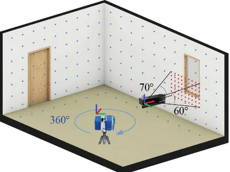
3.3.2 Acquisitions with Kinect sensor are performed parallel to laser scanner acquisitions, on limited areas of the window frames and door jambs. Dense point clouds of these areas are required to be able to reconstruct their geometry. A schematic illustration of this protocol is presented on Figure 4.
Figure 4. Simplified schema of acquisition protocol
Kinect sensor can be used either placed on a static tripod or in a dynamic way by using the Kinect Fusion tool available in the Software Development Kit (SDK). In the first case, a point cloud is obtained from one static viewpoint and thus does not
represent the complete geometry. The second solution has been chosen, since Kinect Fusion enables the dynamic acquisition of a mesh from the whole geometry with a satisfactory quality. The mesh is then transformed into a dense point cloud. Both superimposed data are depicted in Figure 5.
a) b)
Figure 5. Mesh and corresponding segmented point cloud (dark blue) of window frame (a), and door jamb (b)
One should be aware that the use of Kinect Fusion requires some practice. Some trials are necessary before the acquisition of a complete mesh without significant deformation.
4. COMBINATION OF TLS POINT CLOUD AND KINECT DATA
4.1 Pre-location of concerned areas
Before the registration of both datasets, the concerned areas need to be segmented into the TLS point cloud. A first segmentation into rooms and walls can be performed, for instance with an algorithm as proposed by (Macher et al., 2015). Once walls are known, an approach would consist on using radiometric information provided by the scanner camera (on board) in order to detect elements such as windows and doors. These elements can then be extracted based on histogram thresholding. The result obtained after this process is shown for 3 windows on Figure 6.
Figure 6. Result of window extraction based on radiometry. Point cloud of one window after manual segmentation of
remaining outliers (in red) is shown in the right frame.
Because of artifacts such as window awnings, a manual segmentation of the obtained result is often still necessary in order to keep only the window frame or the door jamb.
4.2 Registration of the elements into TLS point cloud
Once window frames and door jambs have been pre-detected and segmented from TLS data, the point clouds deduced from Kinect meshes have to be registered on these frames. Two main challenges are reported during this registration step. First of all, the point densities are highly different between both types of data. The frames coming from TLS point clouds commonly
have a point spacing varying from some millimeters up to some centimeters. Point clouds computed based on Kinect meshes' vertices on the contrary always present a high density of points (about 1 mm between two points or less). In this paper, the density difference has been reduced through a 2 mm spatial resampling of Kinect-based point clouds. A second key challenge deals with the spatial extent of data. Kinect data have been acquired on a spatially limited area of the frames, thus the recovery between point clouds to register is low. This can lead to a non-robust data registration, which has been handled through a manual intervention in this paper.
The 3DVEM software developed by the research group GIFLE of the University of Valencia can be used while working with heterogeneous data (Lerma et al., 2015). This academic solution first requires a user input to add the coordinates of common points in both datasets. However, due to the poor recovery between both types of data used in this paper, a user intervention is required between coarse and fine registration. This is not possible during registration with 3DVEM, that is why the free software CloudCompare has been used. It allows the user to interact not only on the coarse registration requiring at least 4 selected common points, but also on the refinement thus not occluded, which is not the case for doors.
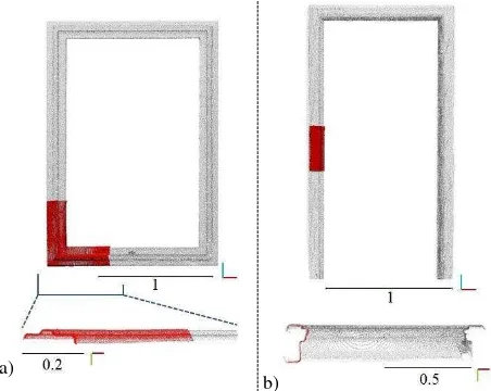
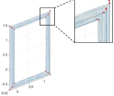
4.2.1 Window: Kinect acquisitions of the window have been realized on a corner of the frame. The segmented Kinect point cloud that has to be registered is thus L-shaped, containing points on two parts of the window frame. The manual selection of at least 4 common points on both Kinect and TLS data leads to a coarse registration. It is then refined calling the ICP algorithm implemented in CloudCompare software. The registration provides a satisfactory result and is suitable in this case as shown on Figure 7a, since common points are not on a unique direction. Moreover the outdoor side of window frame on the building façade is not considered in the proposed indoor approach, thus only one side needs to be reconstructed.
a)
b)
Figure 7. Segmented window frame (a) and door jamb (b) from TLS point clouds with the registered Kinect point clouds (red);
front views (up) and bottom views (down)
4.2.2 Door: Difficulties encountered with door jambs are twofold. Firstly, both sides of the jamb appear in the indoor point cloud, inside and outside the room. However, depending on the scanner location and distance towards the door, points are often missing between both jamb sides. The door wing also contributes to a lack of points on this intermediate area. Secondly, Kinect acquisitions have been carried out at an intermediate height in the middle of one vertical jamb part, but not on a corner (Figure 7b). For these reasons, the registration of Kinect point cloud was non-robust here. Because of the lack of recovery and of the linear distribution of common points, performing an ICP produces a destructive effect so that only the manual coarse registration has been achieved. It has been refined with manual rotations of Kinect data to better align the visible edges of both datasets. To increase the robustness of the method, a further idea would consist on introducing verticality constraints on the data during the registration.
5. RECONSTRUCTION OF OPENINGS TO COMPLETE INDOOR MODELS
This section reports on the processing chain implemented into the Matlab software to reconstruct the considered elements, based on previously combined data.
5.1 Definition of a new reference system
To make the upcoming processing easier, registered point clouds need to be transformed in a local reference system. frame or door jamb. The angle formed by the normal vector of this plane and the nearest reference axis is then calculated and used to compute a rotation matrix. A transformed point cloud of the frame is finally obtained. The frame directions are aligned with two axes of the new reference system, and the normal vector of its mean plane follows the third axis direction. Since Kinect point cloud has been registered before with TLS data, it is also transformed thanks to the same rotation matrix.
5.2 Frame axes detection
To define the main axes of the window frame or door jamb to reconstruct, the segmented TLS point cloud is used. It is first divided into left, right and upper parts in the case of door jamb, as well as a fourth lower part for the window frame. On these respectively 3 or 4 individual point clouds previously projected on a 2D plane, a robust Principal Component Analysis (PCA) algorithm is performed. It enables to detect the axes that better define the direction of each individual part of the frame. An example is shown on Figure 8 with axes displayed on left part (yellow) and upper part (green) of the window frame.
For each part, only representative detected lines are retained and averaged to obtain a mean axis. This step unfortunately still requires a user intervention to determine which lines should be kept. Moreover, assuming the fact that axes are orthogonal in most of the frames, assumptions are made about verticality or horizontality of the axes. Thus they are forced to follow reference axes directions. The same principle is applied for a door jamb, but without the lower part.
Figure 8. Axes detected after PCA computation on left part (yellow) and upper part (green) of the window frame
The mean axes of each part are projected on a same plane (the mean plane of the frame) and used to compute successive axes intersections. This enables to rebuild the 4 frame corners. For a door jamb, the lower corners are determined as the intersections of left and right axes with a plane modeling the ground.
5.3 Creation of geometrical primitives
The detailed geometry of the window frame or door jamb is now determined using exclusively the Kinect point clouds of higher point density than TLS data.
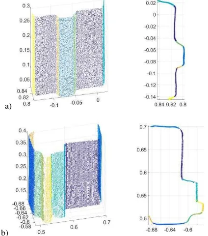
5.3.1 Segmentation into planar primitives is first performed on the Kinect point clouds. Since the geometries of both window and door are composed of several faces, these first need to be segmented. For this purpose, a RANSAC-based approach is applied. It enables to determine the parameters of the planes that best fit each face. The inlier points of each fitted plane are finally kept. The resulting point clouds divided into planar primitives are shown on Figure 9.
a)
b)
Figure 9. Result of segmentation into planar primitives applied on Kinect point clouds of window (a) and door (b).
3D view (left) and profile view (right)
Owing to the detected planes which may be small (a few centimeters), planes that are very near according to a distance criterion and with almost the same directions are fused. This can be seen for the violet plane on Figure 9a.
For more robustness, the MLESAC variant of RANSAC mentioned in Subsection 5.1 is applied. Indeed some faces count a low number of points as seen for instance with yellow and orange planes on Figure 9b. Besides, if the faces are assumed to be orthogonal, the algorithm can be modified to rectify the plane parameters during their computation. Their normal vectors are thus forced to meet horizontality or verticality condition. This is all the more important given that some plane parameters are defined based on a few amount of points, leading to distorted parameters. These deformations are also partially due to the sensor used.
5.3.2 Determination of edges: Once all planar primitives of the dense point cloud have been estimated, a research of neighbor planes is performed. For each primitive, the 7 nearest neighbors of each point are searched. The neighbor points belonging to the primitive itself are not kept, whereas the neighbors near the edges and belonging to another primitive enable to link the two involved primitives. Then plane intersections based on the neighborhood knowledge are computed to define the edges. Provided that edges are assumed to be vertical or horizontal for the considered frames, directions of the created lines are corrected to meet this condition (Figure 10). Hence all the edges of the frame part where Kinect data has been registered are known.
a) b)
Figure 10. Kinect dense point clouds with computed edges (red) and edges with corrected vertical direction (green). Case of the window frame (a) and of the door jamb (b)
5.3.3 Intersections on frame corners: To complete the partial wireframe model obtained so far, edges need to be defined on each remaining part of the frame for which no Kinect acquisitions are available. Provided that the geometry is constant all along the frame, the already computed edges just need to be repeated. A first step consists on creating planes going through each of the previously determined corners of the frame (Subsection 5.2). These planes have normal directions tilted of ±45 degrees from the horizontal, with the sign depending on their location. Regarding the door jamb, only two planes are created on both sides of the upper part, since right and left parts of the jamb intersect with the ground plane at the bottom. The principle is illustrated on Figure 11.
a) b)
Figure 11. Window frame (a) and door jamb (b) represented with tilted planes on the corners
The intersection points between firstly determined edges and the tilted plane they cross are then computed. Assuming that the edges of the next frame part are perpendicular to the previous ones, their direction is known. Hence the edges of this second part can be entirely determined, using the intersection points as centroids. This projection step is finally repeated for the remaining parts, leading to determination of all edges on each part of the frame. The successive intersections enable to obtain characteristic points on each corner (Figure 12), and they now need to be connected.
Figure 12. Characteristic points (in red) belonging to frame edges and projected on the corners of the frame
5.4 Exportation of the primitives
To obtain a good visual rendering and to make the importation of the resulting model easy in 3D processing software, a mesh in .obj format is created using Matlab. The structure of an .obj file first contains the 3D coordinates of each vertex of the mesh, and then the faces defined by a combination of three indexes of vertices for the triangulation. The vertices available so far are the points coming from edges intersections and mapped on the frame corners. By sorting the vertices with successive indexes and knowing the final number of faces of the mesh, a quick computation enables to define all triangles through their three vertices.
The created meshes of door and window have been integrated in a 3D architectural BIM software such as ArchiCAD (Graphisoft). The result of an arbitrary scene containing one door and one window is presented on Figure 13.
a) b)
c)
Figure 13. Reconstructed meshes of door (a) and window (b), and (c) visualization in a 3D scene using ArchiCAD
6. RESULTS ANALYSIS
The created meshes presented in the previous section are visually satisfactory and seem to be almost complete. However, this does not ensure an accurate geometry reconstruction. Thus quality of the results still needs to be assessed.
6.1 Registration assessment
The way TLS and Kinect data have been registered has an influence on the final model quality, since both of them are used for different purposes during the model reconstruction. For the registration of data acquired on the window, an overall error of 3 to 4 mm after ICP processing is reached. Regarding the Kinect technology used to acquire the dense point cloud, this registration error seems to be coherent. Such a remaining error can be reached on this first case since the registration is performed with quite favorable conditions according to available data, as described in Subsection 4.2.1.
It is more difficult to assess the quality of data registration for point clouds acquired on the door. Because of unfavorable registration conditions (see Subsection 4.2.2), ICP algorithm degrades the coarse alignment. Thus the registration quality only depends on the manual selection of common points. The approval of the registration only results on a visual quality check of the registered data. This particular step of the proposed approach is highly non-robust and needs to be improved.
6.2 Reconstruction assessment
To become a global idea of how accurate the geometry has been reconstructed, acquired real data and computed data are compared. For this purpose, a cloud to mesh comparison between TLS point cloud and the reconstructed mesh is carried out. In order to use a point cloud that best corresponds to the ground truth, the point cloud obtained with the highest density
during acquisition time estimations is used (see Subsection 3.3.1). The results computed using CloudCompare are shown on Figure 14a for the window and 14b for the door. It appears that a mean deformation of about -1 and 3 mm respectively is observed for the entire frames, and global dimensions are respected.
a)
b)
Figure 14. Colorized visualization of deformations (in mm) of the created meshes using cloud to mesh
comparison (CloudCompare)
To concentrate essentially on the geometry of the models, sections of window frame and door jamb have been drawn from effective measurements carried out with a measuring tape. They are then compared with sections created along a median plane of the reconstructed meshes. True and reconstructed sections are depicted together on Figure 15. Deformations of a few millimeters especially near the edges and also observed during cloud to mesh comparisons are confirmed on these profiles. However, sections of real and reconstructed frames are very similar, meaning that the reconstructed frames already provide useful and complete information about the global geometry.
a) b)
Figure 15. Comparison of a section realized on the created mesh (dark blue) and a true section (green). Case of window frame (a) and of door jamb (b)
6.3 Discussion and improvements
Some limitations or assumptions in the proposed method have been mentioned all along this paper, and will be recalled here.
6.3.1 Repeatability of plane segmentation: According to the definition of RANSAC algorithm, the RANSAC-based plane segmentation applied in the methodology (Subsection 5.3.1) delivers random results. To assess how repeatable this segmentation step is, it has been repeated 100 times with the same Kinect point cloud of the window frame. The 6 expected planes have been well segmented 83 times out of 100, it is thus quite repeatable. The results are more variable with the door jamb, which has a more complex geometry leading to Kinect point cloud of lower quality. In this case, even though 11 planes are detected as expected, those are not always the good ones.
6.3.2 Considering the processing chain, it appears that the results it provides highly depend on the kind of window frames or door jambs encountered. Some thresholds involved during the segmentation into geometrical primitives need to be changed, depending for example on the number or dimensions of faces. Moreover, the primitive estimation has been limited to planar primitives, whereas moldings could have curved profiles. Also assumptions about verticality or horizontality of the planes that best fit the frame or jamb faces are made. This leads to the construction of a geometry containing orthogonal faces. Nevertheless, this is not always true and such an assumption would result in the creation of a simplified model in some cases. Finally, due to Kinect sensor limitations, only a small part of the frame or jamb is used for the whole frame reconstruction. The frame geometries are thus assumed to be constant. Changes in the geometry along the frame would require the investigation of another acquisition and processing methodology.
6.3.3 Acquisition and registration steps: Regarding the small-scale acquisitions carried out with the Kinect, limitations have been encountered during heterogeneous data integration. As a matter of fact, the mesh creation process is very sensitive towards user displacements while making use of Kinect Fusion. To avoid significant deformations caused by large areas acquisition, the meshes have thus been limited to small parts of the frames. Limitations in terms of accuracy for such a device are also known, that is why a change of the sensor used to complete the TLS data could be investigated. A dedicated handheld scanning device as for instance a FARO Freestyle3D would undoubtedly provide point clouds of higher accuracy on larger areas, leading to a more favorable and more robust registration with TLS data. Besides, the registration itself needs to be improved, with the use for example of 3D keypoint detectors and descriptors in order to reduce user interventions.
Figure 16. Example of a specific case where the cable duct surrounding door jamb would compromise acquisitions
To go further, the whole acquisition protocol can be discussed in some specific cases where digital sensors would encounter problems. To illustrate this issue, the example of a door frame surrounded by cable ducts is shown on Figure 16. In that case, an easier solution would consist on using a measuring tape to determine the global dimensions of the frame, as well as the geometry dimensions.
7. CONCLUSION
This paper reports on an original combination of two heterogeneous datasets used within a modeling approach of building elements such as door jambs or window frames. Global acquisitions of building structural elements have been performed through a well-known acquisition protocol using a terrestrial laser scanner. To complete them, point clouds of the considered building elements have been acquired thanks to a low cost RGB-D sensor used as a handheld scanner. The idea of saving time during acquisitions performed in parallel and by limiting the TLS scans density has been verified.
Based on the TLS point clouds of lower density, the location and the direction of the elements are derived. Through a detailed processing chain, meshes in .obj format are reconstructed. It has been shown that they can easily be integrated into a 3D scene. Unfortunately the accuracy of the reconstruction is correlated with the precision offered by the Kinect sensor. Nevertheless, deformations of some millimeters do not hinder to obtain consistent representations. The actual geometries could be sufficient to build a library of building openings in order to automatically detect them in large TLS point clouds afterwards.
According to the developed approach, some thresholds and assumptions are involved based on a previous knowledge of the artifact geometry. Due to the constraints directly related to the reconstructed elements, the process is for the moment hardly generalizable to other frames. Improvements need to be considered for more repeatability, but also regarding the registration of heterogeneous data. This particular topic represents a still burning issue which requires further works to be extended to other kinds of data, as well as to properly take into account the differences in terms of precision and point density.
REFERENCES
Barazzetti, L., Banfi, F., Brumana, R., and Previtali, M., 2015. Creation of parametric BIM objects from point clouds using NURBS. The Photogrammetric Record, 30(152), pp. 339-362.
Boehm, J., Becker, S., Haala, N., 2007. Model refinement by integrated processing of laser scanning and photogrammetry. In:
The International Archives of the Photogrammetry, Remote
Sensing and Spatial Information Sciences, Zurich, Switzerland,
Vol. XXXVI-5/W47.
Henry, P., Krainin, M., Herbst, E., Ren, X., and Fox, D., 2012. RGB-D mapping: Using Kinect-style depth cameras for dense 3D modeling of indoor environments. The International
Journal of Robotics Research, 31(5), pp. 647-663.
Huai, J., Zhang, Y., and Yilmaz, A., 2015. Real-time large scale 3D reconstruction by fusing Kinect and IMU data. In: The
International Annals of the Photogrammetry, Remote Sensing
and Spatial Information Sciences, La Grande Motte, France,
Vol. II-3/W5, pp. 491-496.
Lachat, E., Macher, H., Landes, T., and Grussenmeyer, P., 2015. Assessment and calibration of a RGB-D camera (Kinect v2 sensor) towards a potential use for close-range 3D modeling.
Remote Sensing, 7(10), pp. 13070-13097.
Lerma, J L., Cabrelles, M., and Navarro, S., 2015. Fusion of range-based data and image-based datasets for efficient documentation of cultural heritage objects and sites. In: The International Archives of the Photogrammetry, Remote Sensing
and Spatial Information Sciences, Taipei, Taiwan, Vol.
XL-5/W7, pp. 277-281.
Macher, H., Landes, T., and Grussenmeyer, P., 2015. Point clouds segmentation as base for as-built BIM creation. In: The International Annals of the Photogrammetry, Remote Sensing
and Spatial Information Sciences, Taipei, Taiwan, Vol.
II-5/W3, pp. 191-197.
Ochmann, S., Vock, R., Wessel, R., and Klein, R., 2016. Automatic reconstruction of parametric building models from indoor point clouds. Computers & Graphics, 54, pp. 94-103.
Thomson, C., and Boehm, J., 2015. Automatic geometry generation from point clouds for BIM. Remote Sensing, 7(9), pp. 11753-11775.
Torr, P. H., and Zisserman, A., 2000. MLESAC: A new robust estimator with application to estimating image geometry.
Computer Vision and Image Understanding, 78(1), p. 138-156.
Tuttas, S., and Stilla, U., 2011. Window detection in sparse point clouds using indoor points. In: The International Archives of the Photogrammetry, Remote Sensing and Spatial
Information Sciences, Munich, Germany, Vol.
XXXVIII-3/W22, pp. 131-136.
Tuttas, S., and Stilla, U., 2012. Reconstruction of rectangular windows in multi-looking oblique view ALS data. In: The International Annals of the Photogrammetry, Remote Sensing
and Spatial Information Sciences, Melbourne, Australia, Vol.
I-3, pp. 317-322.
Valero, E., Adan, A., Huber, D., and Cerrada, C., 2011. Detection, modeling, and classification of moldings for automated reverse engineering of buildings from 3D data. In:
Proceedings of the 28th International Symposium on
Automation and Robotics in Construction, Seoul, Korea, pp.
546-551.
Vosselman, G., 2002. Fusion of laser scanning data, maps, and aerial photographs for building reconstruction. In: International
Geoscience and Remote Sensing Symposium, Vol. 1, pp. 85-88.
Xiong, X., Adan, A., Akinci, B., and Huber, D., 2013. Automatic creation of semantically rich 3D building models from laser scanner data. Automation in Construction, 31, pp. 325-337.