PRELAUNCH PHOTOGRAMMETRIC CALIBRATION OF RUSSIAN SATELLITE
ELEKTRO-L IMAGERY INSTRUMENTS
U.M. Gektin a, N.A. Egoshkin b *, V.V. Eremeev b, A.E. Kuznetcov b, A.M. Kochergin b
a
JSC "Russian Space Systems", 111250, Russia, Moscow, 53, Aviamotornaya Str. – [email protected] b Ryazan State Radio Engineering University, 390005, Russia, Ryazan, 59/1, Gagarin Str. – [email protected]
Special Sessions, SpS 8
KEY WORDS: Photogrammetric, Geostationary Satellites, Sensor Calibration, Control Point Detection, Geometric Model Acquisition
ABSTRACT:
Technology of prelaunch geometric calibration of multispectral imagery instruments of Russian geostationary satellites “Elektro-L” No.1 and No.2 is considered. Circular control points are used as a test field. Its geometrical model is developed to take distortions in the collimator optical system into account. Multiple observations of a test field at different angles is used to cover the full visual field of a geostationary sensor. New algorithm of circular control point detection is developed and adapted to complex geometry of geostationary imagery. It is capable of processing images formed as a set of separate scans. Under calibration, sensor design parameters and also the law of scanning mirror motion are specified. The paper contains results of the technology approval under prelaunch calibration of MSU-GS sensors for geostationary operational meteorological satellites (GOMS) “Elektro-L” No.1 and No.2.
* Corresponding author
1. INTRODUCTION
The issue of prelaunch photogrammetric calibration of multispectral imagery instruments of Russian geostationary satellites “Elektro-L” No.1 and No.2 is considered. Image formation is carried out with usage of a scanning mirror in these instruments, besides the image is constructed in the form of separate parts – scans. Calibration is required to provide high accuracy of scans’ coregistration and eliminate geometrical deformations, which are typical of the scanning process, under processing of imagery materials.
Methods of the prelaunch (laboratory) geometrical calibration are widely presented in publications, for example reviews in (Clarke, 1998). Generally two tasks should be solved for calibration – choice of a reference input image (target) and choice of a camera model fitting. Then methods of the image analysis at the camera output are constructed for estimation of concrete parameters of the camera model.
First of all, collineatory transformations (Heikkilä, 2000), distortion and other deformations of optics of various types (Atcheson, 2010) are considered in publications as a geometrical camera model. Image analysis methods at the camera output providing high-precision determination of such geometrical models are developed for them.
As a rule, sensors have more complicated models for Earth remote sensing systems (Jacobsen, 1998). The sensor design can describe the law of scanning of a sensor in the form of enough composite function r0(m,n,P) depending on a vector of design
factors P . Since the scanning law of a geostationary sensor is complicated, calibration is reasonably arranged taking general assumptions about the camera model fitting into account. In this case, use of a test-field having a great number of control points
located at equal interval is the most suitable. Besides, it is impossible to use control points having a complex form and individual features as in (Atcheson, 2010) or with complex internal structure (Wang, 2011) because of the small size.
2. GEOSTATIONARY SENSOR CALIBRATION TECHNOLOGY
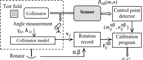
Figure 1 shows a suggested circuit of the geometrical calibration technology for a geostationary sensor.
A test-field containing a system of round control points is used for calibration. Position of a circle on the plate is determined by the index( ji, ), i=1,...,N, j=1,...,N, N – a number of apertures in one row.
A test-field is located into the collimator which optical system forms a real image of the infinitely remote test-field. Visible position of apertures is described by vectors vij in the
collimator system of coordinatesXYZ .
Figure 1. Circuit of the geometrical calibration
Сollimator Sensor
Collimator model
Rotator γkl, λ kl
α,β
Calibration program Bαβ(m,n)
) , (mijαβ nijαβ
vij
αβ
ij r Test field
Angle measurement
Rotation record
Control point detector
F,G
The International Archives of the Photogrammetry, Remote Sensing and Spatial Information Sciences, Volume XLI-B6, 2016 XXIII ISPRS Congress, 12–19 July 2016, Prague, Czech Republic
This contribution has been peer-reviewed.
The collimator model expresses v through ij ( ji, ), besides
projective and lens distortions are taken into account. Visible angle coordinates γkl,λkl of some control points are measured for the model construction. This operation is rather labour-consuming; however it is enough to execute this operation only for a small number of apertures. It should be noted that There is a possibility of the collimator rotation to angles α, in β order to execute calibration of the full field of vision. The image
formed at the output of a sensor is described by vectors rijαβ,
and the image Bαβ(m,n) is formed as a result of imagery.
Basis of the calibration automated technology is a program of identification and measurement of aperture coordinates (control point detector). It executes an automatic identification of apertures, determination of indices (i,j) and high-precision known algorithms ensuring good detection even under conditions of partial screening (Atcheson, 2010), however they use other types of test fields. The paper considers a new algorithm for detection of circular control points. It ensures operation even for separate parts of the image, maximally using prior data on geometry of the sensor scanning.
Calibration is completed with estimation of the scanning law precisely. It is only necessary to obtain the scanning law in the form of function r(m,n). This task is solved by two stages. Firstly, the vector of design parameters is estimated according to the least square method on the basis of
and trigonometric polynomials is used as a function F, G. The first ones take peculiarities of the sensor design and distortion into consideration, the second ones - irregularity in speed of the mirror rotation. Polynomial coefficients according to the least square method are found based on the condition
estimated according to the level of residuals.
3. EXPERIMENT AND ANALYSIS
The suggested technology has been approved under geometrical calibration of scanning sensors MSU-GS for spacecraft “Elektro-L” and “Elektro-L No.2”. Modules of the visual range (VR) and infrared range (IR) were calibrated separately. Table 1 represents data on mode and results of the calibration.
Parameter VR IR
Number of spectral channels 3 7 Scanning by the mirror one-axis two-axis
Parts of images (scans) 2 35
Angular dimensions of the test field 3.7º×3.7º 2º×2º
N 185 31
Number of imageries executed under various angles α, β
45 60
Total volume of information for processing
50 GB 105 GB
Number of detected control points in one channel
~500000 ~49000
Calibration accuracy (residuals) 0.2 pix 0.3 pix
Table 1. Modes and results of MSU-GS calibration
Within calibration of the visual range, periodic geometry frame nonlinearity having the amplitude up to 3 pixels was detected. It is obvious that this nonlinearity is connected with nonlinearity of the scanning mirror motion. Trigonometric polynomials have been used for its correction.
On the left Figure 2 shows a partial image formed by the sensor under imagery of the reference sample in the infrared range IR4. Separate parts of the image are visible. On the right the image geometrically transformation into the uniform system of coordinates is shown; scans stitching operation has been executed. Control point center coordinates found by the program are shown by cross wires.
Figure 2. Example of the image formed by Elektro-L in the geometrical calibration of imagery instruments of Russian geostationary satellites “Elektro-L” No.1 and No.2 have been developed. Suggested approaches allow significantly decreasing calibration labor intensity and increasing its accuracy. Peculiarity of the technology is a possibility of high-accuracy mutual overlapping of scans and also improvement of the scanning mirror motion law. Such technology can be used for calibration of other sensors having the similar principle of scanning.
The International Archives of the Photogrammetry, Remote Sensing and Spatial Information Sciences, Volume XLI-B6, 2016 XXIII ISPRS Congress, 12–19 July 2016, Prague, Czech Republic
This contribution has been peer-reviewed.
REFERENCES
Atcheson, B., Heide, F., Heidrich W., 2010. CALTag: High Precision Fiducial Markers for Camera Calibration. In: 15th International Workshop on Vision, Modeling and Visualization, Siegen. Pp. 41-48.
Clarke, T., Fryer J., 1998. The development of camera calibration methods and models. Photogrammetric Record, 16(91), 51-66.
Heikkilä, J., 2000. Geometric Camera Calibration Using Circular Control Points. IEEE Transactions on Pattern Analysis and Machine Intelligence 22, 1066–1076.
Jacobsen, K., 1998. Geometric Calibration of Space Remote Sensing Cameras for Efficient Processing. International Archives of Photogrammetry and Remote Sensing, Vol. 32, Part 1, pp. 33-43.
Wang Z., 2011. Advanced geometric camera calibration for machine vision. Optical Engineering, Vol. 50, No. 11, 110503.
The International Archives of the Photogrammetry, Remote Sensing and Spatial Information Sciences, Volume XLI-B6, 2016 XXIII ISPRS Congress, 12–19 July 2016, Prague, Czech Republic
This contribution has been peer-reviewed.