PERFORMANCE EVALUATION OF 3D MODELING SOFTWARE FOR UAV
PHOTOGRAMMETRY
H. Yanagi a, c, *, H. Chikatsu b a
Japan Association of Surveyors, 1-33-18, Hakusan, Bunkyo-ku, Tokyo, Japan – [email protected]
bDivision of Architectural, Civil and Environmental Engineering, Tokyo Denki University, Hatoyama, Hiki-gun, Saitama, Japan - [email protected]
c
School of Science and Engineering, Tokyo Denki University, Hatoyama, Hiki-gun, Saitama, Japan Commission V, WG V/1
KEY WORDS: UAV Photogrammetry, 3D Modeling software, Structure from Motion, Evaluation of Accuracy Aspects
ABSTRACT:
UAV (Unmanned Aerial Vehicle) photogrammetry, which combines UAV and freely available internet-based 3D modeling software, is widely used as a low-cost and user-friendly photogrammetry technique in the fields such as remote sensing and geosciences. In UAV photogrammetry, only the platform used in conventional aerial photogrammetry is changed. Consequently, 3D modeling software contributes significantly to its expansion. However, the algorithms of the 3D modelling software are black box algorithms. As a result, only a few studies have been able to evaluate their accuracy using 3D coordinate check points. With this motive, Smart3DCapture and Pix4Dmapper were downloaded from the Internet and commercial software PhotoScan was also employed; investigations were performed in this paper using check points and images obtained from UAV.
* Corresponding author
1. INTRODUCTION
Recently, UAV (Unmanned Aerial Vehicle) photogrammetry, which combines UAV and freely available internet-based 3D modeling software, has been receiving attention as a low-cost and user-friendly photogrammetry technique in various fields. The development of high performance and user-friendly 3D modeling software has contributed significantly to the expansion of UAV photogrammetry.
3D modeling software or SfM (Structure from Motion) is composed of a matching, scene reconstruction, and point cloud generation functions. In conventional photogrammetry, expensive equipment and extensive experience are required, and it is necessary to determine the position and orientation of the camera beforehand using GCPs (Ground Control Points), etc. However, 3D modeling software can obtain such camera information from multi-view image without using GCPs. Consequently, the effectiveness of UAV photogrammetry using 3D modelling software has been receiving attention for 3D measurement of very dangerous areas, such as landslide zones (Niethammer et al., 2010) and Greenland ice sheets (Ryan et. al., 2015).
In general, precision and accuracy are used to evaluate 3D measurement from the viewpoint of photogrammetry. Because algorithms for 3D modeling software is a black box and generated 3D model is similarity model, the accuracy of a 3D modeling software should be verified after transforming the similarity model to an absolute model using GCPs, which are known coordinates. Various 3D modeling software have been verified in this way (Rosnell and Honkavaara, 2012; Vallet et al., 2011; Neitzel and Klonowski, 2011), evaluation of 3D modeling software from the viewpoint of photogrammetry has been insufficient.
With this motive, Smart3DCapture and Pix4Dmapper were downloaded from the Internet and commercial software PhotoScan was also employed; investigations were performed in this paper using CPs (Check points) and images obtained from UAV.
2. EXPERIMENTS
2.1 UAV and camera
A hexarotor UAV and camera in Table 1 were used in this study. A SLR (Single Lens Reflex) camera was utilised because its accuracy is influenced significantly by resolution (Kung et al., 2011).
UAV
Type: hexarotor
Length: 900 mm (Length of rotor: 390 mm) Weight: body, 4 kg; Battery, 1.63 kg
Camera
Canon EOS Kiss X7
Image size: 5184 × 3456 pixels Image sensor: 22.3 × 14.9 mm Weight: 370 g
Lens
Canon EF20mm F2.8 USM Focal length: 20 mm Weight: 405 g
Table 1. Specifications of UAV and Camera 2.2 Test site and images
and 100 m (H = 100 m) above ground level, respectively, using SLR and UAV at one-second intervals, without using GPS, IMU, three acceleration sensor nor three gyroscope.
Thus, performance of each software are evaluated using the mean square error in the check points after generating the 3D model by automatic process function of software. In this study, the images that are used in all verification are not pre-processing to input image and post-pre-processing to output results for keeping fair of verification.
3. PERFORMANCE EVALUATION
Table 2 shows the various 3D modeling software found in the literature regarding UAV photogrammetry.
3D modeling software Literature
Autodesk 123D Catch Micheletti et al., 2014, 2015
Photosynth Neitzel and Klonowski, 2011
Rosnell et al., 2011
Rosnell and Honkavaara, 2012
Bundler Neitzel and Klonowski, 2011
SfMToolkit Niethammer et al. 2010
Turner et al., 2011 Westoby et al., 2012 Harwin and Lucieer, 2012 Neitzel and Klonowski, 2011 Genchi et al., 2015
PhotoModeler Micheletti et al., 2014, 2015
PhotoScan Pro. Doneus et al., 2011
Verhoeven, 2011
Pix4Dmapper Vallet et al., 2011
Oda et al., 2015
Table 2. 3D modeling software researched and corresponding studies
PhotoScan and PhotoModeler are commercial software. Autodesk 123D Catch, Photosynth, Bundler, SfMToolkit, and Pix4Dmapper (simplified version) are free software that can be downloaded from the Internet. Smart3DCapture (simplified version) is also able for download from the Internet. In this
study, performance of Pix4Dmapper
(https://pix4d.com/products/) and Smart3DCapture (http://www.acute3d.com/), which were downloaded from the Internet, and the commercial software PhotoScan were evaluated. It should be noted that Smart3DCapture (simplified version) has recently changed name to ‘ContextCapture’ and will be available for only a limited time.
The 3D model (point cloud data) which is automatically generated by the 3D modeling software is a similarity model. In order to verify the accuracy of the CPs, the coordinate system of
the 3D model has to be transformed from relative coordinates to real-world object coordinates by absolute orientation using GCPs. In this study, 3D Helmert transformation was used for coordinate transformation with more than three GCPs. However, PhotoScan cannot acquire the coordinates of CPs on a relative coordinate system.
Thus, in scenario 1, the performance of Smart3DCapture and Pix4Dmapper after absolute orientation of a similarity model that was automatically generated from the software were verified. On the other hand, Pix4Dmapper and PhotoScan have to acquire the coordinates of CPs on the absolute coordinate system because the absolute model is generated by inputting the coordinates of GCPs in the software and clicking the GCPs points on each image. Consequently, these software were verified in scenario 2 using the directly obtained absolute coordinates.
The type of 3D model and associated software used in each scenario is shown in Table 3.
Scenario No. Type of 3D model 3D modeling software
1 Similarity model Smart3DCapture
Pix4Dmapper
2 Absolute model Pix4Dmapper
PhotoScan
Table 3. 3D model and corresponding software used in each scenario
3.1 Scenario 1
3.1.1 Number of GCPs and accuracy: In this scenario, Smart3DCapture and Pix4Dmapper were verified using the RMSE (Root Mean Square Error) of the CPs after absolute orientation of the similarity model automatically generated by the software. The GCPs selected from the CPs on the test site were evenly distributed, and 3, 5, 7, 9, and 13 GCPs were verified in this study. The position and number of CPs selected were the same regardless of the number of GCPs (H = 100 m: 45 points, H = 50 m: 35 points).
(i) H = 100m
Table 4 shows the horizontal and vertical RMSE for CPs for the case where the altitude was 100 m. In Table 3, PA (Proportional Accuracy) is computed using equation (1) (Fraser, 1987):
where DX, DY, and DZare the object field diameter; and σX, σY,
Table 4. Horizontal and vertical accuracies (H = 100 m) In addition, the performance was verified using four GCP
number of GCPs that was selected was seven. The results for 3 GCPs and 7GCPs listed in Table 4 show the average values obtained.
From Table 4, it is clear that Pix4Dmapper is more accurate than Smart3DCapture in each number of GCPs. However, let take into account that the resolution for one pixel is 22 mm (H = 100 m), it should be understood that the practical accuracy which is a conventional photogrammetry technique using the three images, produced results of 2,453, 7,278, and 7,647 for respective number of 7, 9, and 13 GCPs in centre image. Therefore, in order to obtain the same 3D modeling software accuracy using the bundle adjustment method, it is clear that GCPs need more than nine points. The bundle adjustment method improves the accuracy by increasing the number of GCPs; however, it is clear that the 3D modeling software is not significantly effect by the number of GCPs.
(ii) H = 50m
Table 5. Horizontal and vertical accuracies (H = 50 m) Table 5 shows the horizontal and vertical RMSE for CPs for the case where altitude was 50 m. In addition, the number of CPs was 35 at this altitude because the imaging range narrowed. From Table 5, it is clear that Pix4Dmapper is more accurate than Smart3DCapture in each number of GCPs, as was the case for an altitude of 100 m. However, let take into account that the resolution for one pixel was 11 mm (H = 50 m), it is understood that the practical accuracy obtained by these software was at the sub-pixels level, and the number of GCPs necessary for the absolute orientation is understood to be sufficient at three points. On the other hand, computing the PA using the bundle adjustment method and the three images resulted in values of 8,637, 13,080, and 16,581 for 7, 9, and 13 GCPs in the centre image, respectively. Thus, for an altitude of 50 m, the results computed using the bundle adjustment method with nine GCPs is higher than the results that computed using the 3D modeling software. This implies that the respective free versions of Pix4Dmapper and Smart3DCapture, which were downloaded from the Internet, are sufficiently practical for UAV photogrammetry.
From these results, the results obtained from these software are not affected by the number of GCPs. The results show that the accuracy of altitude 100 m is smaller than that for the results at altitude 50 m. It can be seen that the accuracy decreases as altitude increases when the bundle adjustment method is used,
the relationship between altitude and accuracy is discussed in the next section. In addition, considering that the results are not affected by the number of GCPs when using 3D modeling software, the performance is verified using five GCPs in following section.
3.1.2 Altitude and accuracy: Rock et al. 2011 verified that accuracy decreases quadratic curve manner as altitude increases. This relation is defined in equation (2):
where σX0, σY0, and σZ0 are the standard errors; H is the altitude; f is the focal length; B is the baseline; and σP is the pointing accuracy
Therefore, in this section, the relationship between altitude and accuracy is verified from the viewpoint of ground resolution. Table 6 shows results of normalised accuracy, which is the averaged accuracy obtained with five GCPs in Tables 4 and 5 normalised by each ground resolution in terms of altitude. From Table 6, it is clear that the normalised accuracy improves at high altitude. Therefore, it is clear that whereas accuracy decreases with increasing altitude, normalised accuracy increases with increasing altitude. Thus, it can be inferred that matching accuracy is improved because the imaging range is widens with high altitude and more interest points are taken from the image. Conversely, matching accuracy decreases because the images of CPs obtained are small with increasing
3.1.3 Overlap ratio and accuracy: Rosnell and Honkavaara (2012) verified the relationship between overlap ratio and accuracy. They showed that a large overlap reduces the continuous images (Case 1 in Figure 2), nine images (Case 2 in Figure 2, selecting one skip image from 17 continuous images), and six images (Case 3 in Figure 2, selecting two skip images from 17 continuous images) were verified.
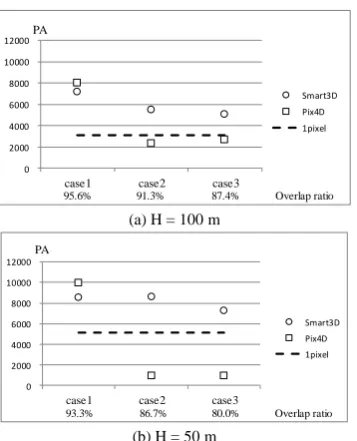
In Figure 2, the overlap ratio in each case is the average value of the overlap ratio between the two images. For H = 100 m, the overlap ratios are 95.6% (Case 1), 91.3% (Case 2), and 87.0% (Case 3). For H = 50 m, the overlap ratios are 93.3% (Case 1)、86.7%(Case 2) , and 80.0% (Case 3).
GCPs. Incidentally, the dashed line in Figure 3 shows the PA corresponding to the ground resolution of one pixel, where at H = 100 m the value is 3,100 and for H = 50 m the value is 5,500. From Figure 3, it is clear that in the case of Smart3DCapture accuracy decreases with decreasing overlap ratio. However, the ground resolution of the sub-pixels level is obtained in each case.
On the other hand, the results for Pix4Dmapper show that the accuracy decreases even in the case of 91.3% overlap ratio. From these results, it is recommended that the overlap ratio be more than 80% for Smart3DCapture and more than 93% for Pix4Dmapper.
3.1.4 Number of image and accuracy: Micheletti et al. (2014) verified that accuracy increases with increases in the number of images. This study speculated whether increases in the number of images result in large overlaps. The relationship between number of images and accuracy using nine images in Case 2 (Figure 2) and nine consecutive images in the vicinity of the centre were verified in this section.
Figures 4 show the results of the investigation into the relationship between number of images and overlap rate. The same applies in Case 3.
From Figures 4, it can be seen that in the case of Smart3DCapture, the accuracy is improved using the nine consecutive images in the vicinity of the centre (Case 2), which remains the same as the number of images decreases. Conversely, in the six images (Case 3), the accuracy does not improve, regardless of altitude.
On the other hand, in the case of Pix4Dmapper, the accuracy significantly improves for both altitudes of 100 m and 50 m using nine images. In contrast, using six images, no improvement in accuracy is observed, regardless of altitude. It is surmised that the available image at both ends of the course in the case of a narrow imaging range is small if a large overlap ratio is adopted at low altitude, whereas in the case of a wide imaging range it is large at high altitude. The accuracy of Smart3DCapture decreases continuously. However, the accuracy of the Pix4Dmapper improves significantly.
Therefore, Pix4Dmapper is estimated to be more robust than Smart3DCapture even when the number of available images is small. Incidentally, the number of images naturally depends on the size of the measurement object, thus it is important that the measurement target is covered with equal multi-view images. 3.1.5 Input order of images and accuracy: In 3D modeling software, it is estimated that images are processed in order using position information recorded in the GPS data, time information, or image name that is recorded in the EXIF information. GPS data were not used in this study. The results obtained by investigating the process order of Pix4Dmapper and Smart3DCapture showed that Pix4Dmapper processes in order using EXIF information and Smart3DCapture processes in order using numbers and image filenames.
Consequently, the performance was evaluated in terms of the time described in the EXIF information of the 17 images randomly changed in Pix4Dmapper. The input order of the images was changed after changing the numbers in the image filenames in Smart3DCapture.
Table 7 shows the results obtained. It should be noted that the results were computed using five GCPs.
Software PA(Before) PA(Changed)
H = 100 m H = 50 m H = 100 m H = 50 m
Smart3D 7153 8529 5863 8114
Pix4D 7998 9985 6871 3821
Table 7. Relationship between input order of images and accuracy
From Table 7, it is clear that accuracy is not influenced by input order of images in Smart3DCapture. However, it is estimated that accuracy is influenced by input order of images in Pix4Dmapper.
3.1.6 Changing of altitude and accuracy : In this study, to investigate the relationship between changing altitude and accuracy, firstly, the effect of combining all 17 images obtained at altitudes 100 m and 50 m were investigated. Table 8 shows the results obtained.
0 2000 4000 6000 8000 10000 12000
case1 case2 case3 PA
Smart3D Pix4D 1pixel
95.6% 91.3% 87.4% Overlap ratio
(a) H = 100 m
0 2000 4000 6000 8000 10000 12000
case1 case2 case3 PA
Smart3D Pix4D 1pixel
93.3% 86.7% 80.0% Overlap ratio
(b) H = 50 m
Figure 3. Relationship between overlap and accuracy
(a) H = 100 m
(b) H = 50 m
Software
Table 8. Results obtained after combining 17 images From Table 8, it is clear that Smart3DCapture accuracy improved as a result of the combination, whereas Pix4Dmapper accuracy decreased.
On the other hand, considering that the accuracy improvement at altitude is low, the changing of accuracy was investigated by using the images obtained at altitude 50 m and adding them to the 17 images obtained at an altitude of 100 m.
Software PA (Before
Table 9. Results obtained using added images Table 9 shows the resulting accuracies computed when one, three and, five images obtained at altitude 50 m are combined and added to 17 images (100 m). From Table 9, it is clear that adding the image obtained at low altitude improves the accuracy in Smart3DCapture, whereas no improvement occurs in Pix4Dmapper. Thus, whereas Smart3DCapture is robust to large vertical movements in altitude accuracy may decrease in Pix4Dmapper.
Therefore, when using Pix4Dmapper, it is recommended that only images obtained at specific altitude be used.
3.2 Scenario 2
Pix4Dmapper and PhotoScan can both obtain the coordinates of CPs on a real-world object coordinate system directly using a 3D model generated automatically after entering the coordinates of GCPs on a real-world object coordinate system and clicking the position of the GCPs on each image shown on the display. Therefore, although this feature both time-consuming and labour-intensive, it is possible to save the absolute orientation step in scenario 1. based on confluence residual minimisation using the multi-view image, and it differs from the bundle adjustment method based on the collinearity condition in photogrammetry. In other words, the coordinates of GCPs have an error in the process of confluence residual minimisation in the case of SfM.
Altitude GCPs/CPs
Table 10. Horizontal and vertical accuracy
Therefore, the absolute orientation is computed regarding the absolute coordinates of the GCPs obtained from the generated absolute model as the initial value—as in scenario 1.
Figure 5 shows the computed results. The results computed using PhotoScan in each case from the initial step of work procedure doesn’t show cm order of accuracy. Thus, the results computed by PhotoScan are not included in Figure 5.
In Figure 5, scenario 2 is shown to have higher accuracy than scenario 1 for altitudes of 100 m and 50 m, and accuracy improves significantly especially at high altitudes. From this result, it can be surmised that the number of image points increases to use constraint condition as residuals minimisation for the image point in the case of high altitude in SfM.
From these results, although scenario 2 by Pix4Dmapper is time-consuming and labour-intensive, the functions of the software are an effective technique that can be performed easily in UAV photogrammetry. Consequently, it is recommended to recompute the absolute orientation using obtained absolute coordinates for improving accuracy.
In addition, the relationship between number of GCPs, altitude, overlap ratio, input order of images, number of images, and changing of altitude; function of software and accuracy were skipped because the direction of the results is same as scenario 1, and the result of using other than the five GCPs is same as five GCPs.
4. CONCLUSION
This paper investigated the performance of freely available, Internet-based 3D modeling software and commercial software from the viewpoint of UAV photogrammetry. The results obtained indicate that both Smart3DCapture and Pix4Dmapper are able to obtain practical accuracy at the sub-pixels level.
Further, whereas Smart3DCapture is not affected by overlap ratio and altitude of vertical movement, Pix4Dmapper is significantly influenced. Therefore, it is recommended that Smart3DCapture be used in cases where there is significant vertical movement in altitude and small overlap ratio (however, more than 80%), and Pix4Dmapper be used in cases where a certain altitude is maintained, such as automatic flight, and there is a large overlap ratio (more than 93%).
In scenario 2 using Pix4Dmapper, the accuracy of the sub-pixel level is obtained as the RMSE of CPs without computing absolute orientation, and the accuracy is improved to compute the absolute orientation using the absolute coordinates of GCPs obtained as the initial value. Further, the accuracy improves significantly at high altitudes.
In this study, the performance of 3D modeling software in UAV photogrammetry was evaluated in a narrow range. In future work, the performance of 3D modeling software in UAV photogrammetry will be evaluated over a broad range, such as using hundreds of images.
REFERENCES
Doneus M., Verhoeven G., Fera M., Brise C., Kucera M., Neubauer W., 2011. From deposit to point cloud—A study of low-cost computer vision approaches for the straightforward documentation of archaeological excavations. Geoinformatics CTU FCE, pp. 81-88.
Fraser C.S., 1987. Limiting error propagation in network design. Photogrammetric Engineering and Remote Sensing, Vol. 53, No. 5, pp. 487-493.
Genchi S.A., Vitale A.J., Perillo G.M.E., Delrieux C.A., 2015. Structure-from-motion approach for characterization of bioerosion patterns using UAV imagery. Sensors, Vol. 15, pp. 3593-3609.
Goncalves J.A. and Henriques R., 2015. UAV photogrammetry for topographic monitoring of coastal areas. ISPRS Journal of Photogrammetry and Remote Sensing, Vol. 104, pp. 101–111. Harwin S. and Lucieer A., 2012. Assessing the accuracy of georeferenced point clouds produced via multi-view stereopsis from unmanned aerial vehicle UAV imagery. Remote Sensing, Vol. 4, pp. 1573-1599.
Kung O., Strecha C., Beyeler A., Zufferey J-C., Floreano D., Fua P., Gervaix F., 2011. The accuracy of automatic photogrammetric techniques on ultra-light UAV imagery. International Archives of the Photogrammetry, Remote Sensing and Spatial Information Sciences, Vol. XXXVIII-1/C22, pp. 125-130.
Lucieer A., Turner D., King D.H., Robinson S.A., 2014. Using an unmanned aerial vehicle (UAV) to capture micro-topography of Antarctic moss beds. International Journal of Applied Earth Observation and Geoinformation, Vol. 27 (Part A), pp. 53-62. Micheletti N., Chandler J.H., Lane S.N., 2014. Investigating the geomorphological potential of freely available and accessible structure-from-motion photogrammetry using smartphone. Earth Surface Processes and Landforms, pp. 473-486. Micheletti N., Chandler J.H., Lane S.N., 2015. Structure from motion (SfM) photogrammetry. British Society for Geomorphology, Geomorphological Techniques, Online Edition (ISSN 2047-0371).
Mancini F., Dubbini M., Gattelli M., Stecchi F., Fabbri S., Gabbianelli G., 2013. Using unmanned aerial vehicles (UAV) for high-resolution reconstruction of topography: The structure from motion approach on coastal environments. Remote Sensing, Vol. 5, pp. 6880-6898.
Neitzel F. and Klonowski J., 2011. Mobile 3D mapping with a low-cost UAV system. International Archives of the Photogrammetry, Remote Sensing and Spatial Information Sciences, Vol. XXXVIII-1/C22, pp. 39-44.
Niethammer U., Rothmund S., James M.R., Travelletti J., Joswig M., 2010. UAV-based remote sensing of landslides. International Archives of Photogrammetry, Remote Sensing and Spatial Information Sciences, Vol. XXXVIII, Part 5, Com. V, pp. 496-501.
Oda K., Hattori S., Saeki H., Takayama T., Honma R., 2015. Qualification of point clouds measured by SfM software. The International Archives of the Photogrammetry, Remote Sensing and Spatial Information Sciences, Vol. XL-4/W5, pp. 125-130. Rock G., Ries J.B., Udelhoven T., 2011. Sensitivity analysis of UAV-photogrammetry for creating digital elevation models (DEM). International Archives of the Photogrammetry, Remote Sensing and Spatial Information Sciences, Vol. XXXVIII-1/C22, pp. 69-73.
Rosnell T., Honkavaara E., Nurminen K., 2011. On geometric processing of multi-temporal image data collected by light UAV systems. International Archives of the Photogrammetry, Remote Sensing and Spatial Informa tion Sciences, Vol. XXXVIII-1/C22, pp. 63-68.
Rosnell T. and Honkavaara E., 2012. Point cloud generation from aerial image data acquired by a quadrocopter type micro unmanned aerial vehicle and a digital still camera. Sensors, Vol. 12, pp. 453-480.
Ryan J.C., Hubbard A.L., Box J.E., Todd J., Christoffersen P., Carr J.R., Holt T.O., Snooke N., 2015. UAV photogrammetry and structure from motion to assess calving dynamics at Store Glacier, a large outlet draining the Greenland ice sheet. The Gryosphere, Vol. 9, pp. 1-11.
Turner D., Lucieer A., Watson C., 2011. Development of an unmanned aerial vehicle (UAV) for hyper resolution vineyard mapping based on visible, multispectral, and thermal imagery. Proceedings of the 34th International Symposium on Remote Sensing of Environment (ISRSE34), pp. 11-15.
Vallet J., Panissod F., Strecha C., Tracol M., 2011. Photogrammetric performance of an ultra light weight swinglet “UAV”. International Archives of the Photogrammetry, Remote Sensing and Spatial Information Sciences, Vol. XXXIII-1/C22, UAV-g 2011 International Conference on Unmanned Aerial Vehicle in Geomatics, pp. 253-258.
Verhoeven G., 2011. Taking computer vision aloft— Archaeological three-dimensional reconstructions from aerial photographs with photoscan. Archaeological Prospection, Vol. 18, pp .67-73.