A PRECISE POSITION AND ATTITUDE DETERMINATION SYSTEM FOR
LIGHTWEIGHT UNMANNED AERIAL VEHICLES
Christian Eling, Lasse Klingbeil, Markus Wieland and Heiner Kuhlmann
Institute of Geodesy and Geoinformation The University of Bonn Nussallee 17, 53115 Bonn, Germany
(c.eling, l.klingbeil, m.wieland)@igg.uni-bonn.de, [email protected]
KEY WORDS:Unmanned Aerial Vehicle, Direct Georeferencing, RTK-GPS, IMU, Extended Kalman Filtering, Real Time Operating System
ABSTRACT:
In many unmanned aerial vehicle (UAV) applications a direct georeferencing is required. The reason can be that the UAV flies au-tonomous and must be navigated precisely, or that the UAV performs a remote sensing operation, where the position of the camera has to be known at the moment of the recording. In our application, a project calledMapping on Demand, we are motivated by both of these reasons. The goal of this project is to develop a lightweight autonomously flying UAV that is able to identify and measure inaccessible three-dimensional objects by use of visual information.
Due to payload and space limitations, precise position and attitude determination of micro- and mini-sized UAVs is very challenging. The limitations do not only affect the onboard computing capacity, but they are also noticeable when choosing the georeferencing sensors.
In this article, we will present a new developed onboard direct georeferencing system which is real-time capable, applicable for lightweight UAVs and provides very precise results (position accuracyσ<5cm and attitude accuracyσ<0.5 deg). In this system GPS, inertial sensors, magnetic field sensors, a barometer as well as stereo video cameras are used as georeferencing sensors. We will describe the hardware development and will go into details of the implemented software. In this context especially the RTK-GPS soft-ware and the concept of the attitude determination by use of inertial sensors, magnetic field sensors as well as an onboard GPS baseline will be highlighted. Finally, results of first field tests as well as an outlook on further developments will conclude this contribution.
1 INTRODUCTION
The acquisition of data by use of mobile platforms has become established in many communities in the recent decades. The rea-son for this is very much influenced by the possibility to allow for an effectively application of mobile systems in wide areas. In this context the demand for unmanned aerial systems (UASs) in-creased in the past ten years. In contrast to other mobile platforms unmanned aerial vehicles (UAVs) have the advantage of being able to overfly inaccessible and also dangerous areas. Further-more, they can get very close to objects to achieve high resolution data with low resolution sensors. Especially in the field of preci-sion farming such as phenotyping or plant monitoring (Xiang and Tian, 2011), or in the fields of infrastructure inspection (Merz and Kendoul, 2011) and recording of archaeological sites (Eisenbeiss et al., 2005) UAVs are meanwhile often deployed.
In most cases UAVs collect object information via remote sens-ing, which means that the data is acquired without physical con-tact to the object. After the data acquisition, during the data analysis (image processing, processing of Lidar data), mostly the question arises: From where was the respective data collected? Thus, remote sensing is always connected with a georeferencing of the UAV.
Generally, UAVs are controlled by an expert pilot. But in many applications manual flights are impossible or even unwanted, since (1) the visual contact between the pilot and the UAV must not al-ways be given, (2) the flight path is preset or (3) the UAV knows better where to fly next, because it is closer to the object. Fur-thermore, wrong decisions of the pilot may lead to disastrous consequences. Thus, also from safety aspects autonomous flights are quite advisable. However, autonomous flights require a reli-able navigation and therefore also a georeferencing of the vehicle. Summarizing, a georeferencing of the mobile platform is needed
for both a remote sensing and navigation.
In principal a distinction must be made between direct and indi-rect georeferencing. Indiindi-rect georeferencing means that ground control points are used to establish the link to a reference frame. Before use, the array of ground control points must first be cre-ated, which is very time-consuming. Furthermore, the identifi-cation of the ground control points in the collected data often requires operator intervention. In contrast, direct georeferencing is achieved from sensors mounted on the mobile platform. These sensors measure the positions and attitudes of the vehicle in a de-fined reference frame, without using ground control points.
Direct georeferencing of UAVs has already been implemented in many systems. Most of them make use of a single L1 C/A code Global Positioning System (GPS) receiver as well as inertial sen-sors (accelerometers, gyroscopes and magnetometers) (Yoo and Ahn, 2003, Merz and Kendoul, 2011, Xiang and Tian, 2011). But the resulting accuracies of such systems (2-10 m position accu-racy and 0.5-5 deg attitude accuaccu-racy) can be insufficient for some applications.
In contrast, high precision direct georeferencing of UAVs by means of differential GPS (DGPS) techniques such as Real Time Kine-matic (RTK) GPS can lead to a position accuracy better than 5 cm. Precise position and attitude determination systems do al-ready exist for large-sized UAVs. For example in (Nagai et al., 2009) the authors describe a direct georeferencing system that makes use of DGPS, a high-grade IMU and a bundle block ad-justment. However, precise direct georeferencing of micro- and mini-sized UAVs is much more challenging. Due to payload and space limitations there are significant restrictions when choosing the hardware components. These limitations do also affect the onboard computing capacity.
were presented in (Rieke et al., 2011) and (Stempfhuber and Buch-holz, 2011). In (Rieke et al., 2011) the authors use a GPRS/UMTS modem to communicate with a reference service (e.g. SAPOS Germany) to allow for the determination of DGPS. However, the presented system does not include an onboard processing unit. Thus, all data has to be transmitted to a ground station via WiFi, which is often an unreliable connection. In (Stempfhuber and Buchholz, 2011) the authors make use of L1 GPS receivers (u-blox LEA4T, u-(u-blox LEA6T), which provide L1 C/A code and L1 carrier phase observations. In combination with L1 antennas these receivers lead to a low-cost and lightweight RTK-GPS ca-pable hardware. Nevertheless, it is well known that the time to fix the ambiguities of single frequency GPS data generally takes a few minutes (Odijk et al., 2007). Furthermore, the GPS process-ing is performed by the GPS processprocess-ing software RtkLib (Takasu and Yasuda, 2009) running on a ground station. Thus, the raw measurements of the rover antenna first have to be transmitted via WiFi in this approach as well.
In our work we aim to develop an onboard direct georeferencing system that is (1) real-time capable at a sampling rate>10 Hz, (2) applicable for lightweight UAVs and (3) leads to very precise re-sults (position accuracyσ<5 cm, attitude accuracyσ<0.5 deg). With this development we are part of a research project called
Mapping on Demand (MOD). The goal of this project is to de-velop a lightweight autonomously flying UAV that is able to iden-tify and measure inaccessible three-dimensional objects by use of visual information.
In this article we will present the current state of the development of the direct georeferencing system. The contribution is struc-tured as follows: In section 2 details on the sensors, how they are mounted on the UAV platform and the construction of the processing unit will be shown. In section 3 we will describe the software development. In this context we will go into details of the RTK-GPS positioning software and the concept to the attitude determination. In section 4 we will present first results of flight tests. Since the system development is not yet completed, we will finally conclude this contribution with an outlook on planned de-velopments (see section 5).
2 SYSTEM DESIGN
In this section the sensors that are used for the precise direct geo-referencing of an UAV and how these sensors are mounted on the mobile platform will be described. Furthermore, the process-ing hardware, that has been developed for real time position and attitude determination will be presented.
2.1 Sensors
As mentioned in the introduction, our UAS is meant to act as a mobile mapping platform. For this purpose two sensor groups are needed: georeferencing sensors and mapping sensors. Since we focus on the direct georeferencing in this article, we will only describe the georeferencing sensors below.
An overview of the onboard georeferencing sensors is shown in Table 1. Accordingly, several sensors with different properties are intended to be used for the position and attitude determina-tion. The system is designed to extend the fusion of the named sensors depending on the level of the software development. In the final stage of the development all sensors will be combined in an optimal way.
The main position sensor is the Novatel OEM628 dual-frequency GPS board. By communication with a master station it allows for a RTK-GPS determination (see section 3.1). Besides the position determination, the Novatel OEM628 is also proposed to provide
Sensor Model Observations Purpose
1 GPS Novatel
OEM628
L1 C/A code, L1 carrier phase, L2 P(Y) code, L2 carrier phase, 10Hz
L1 C/A code, L1 carrier phase, 5Hz
IDS ueye stereo monochrome, 20Hz position and at-titude determi-nation
Table 1: Onboard direct georeferencing sensors.
data for the attitude determination. This happens in combination with the single-frequency receiver u-blox LEA6T. Together, both GPS systems embody a short GPS baseline on the UAV, which can be used for the determination of the heading and one inclina-tion of the platform (Eling et al., 2013). The fusion of the GPS data with the IMU and the stereo camera observations is planned for the future and has several advantages: (1) the higher IMU sampling rate leads to a higher estimation rate, (2) the fusion im-proves the accuracy, (3) the fusion allows for a tightly coupled and therefore more robust GPS processing and (4) the additional sensors may bridge GPS gaps, since they are short-term stable.
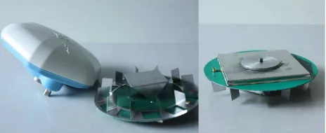
In addition to the named GPS receivers also GPS antennas are needed. Generally, precise dual frequency antennas are too heavy for UAV applications. Since the highest weight of the antennas comes from the protective housing, the antenna connection and the 5/8” screw thread in the bottom of the antenna, we decided to dismantle a geodetic antenna (navXperience 3G+C) (see Fig-ure 1). In this way, we were able to reduce the weight of the antenna from 350g to 100g, whereby the functionality of the an-tenna could be maintained. Certainly, by dismantling the housing of the antenna, the external reference point of the antenna got lost. Thus, a recalibration of the antenna in an anechoic chamber had to be performed, to determine the new phase center offset after the dismantling (Zeimetz and Kuhlmann, 2010).
Figure 1: Comparison of the original and the dismantled dual-frequency antenna navXperience 3G+C. The new external refer-ence point is shown in the right section of the picture.
2.2 Direct georeferencing system
The direct georeferencing system is designed to (1) link the posi-tion and attitude sensors with a processing unit, (2) supply all the hardware with electricity and (3) compute positions and attitudes in real-time.
As processing unit the National Instruments sbRIO-9606 is used. Even if the size of this board is relatively large (10.3 cm x 9.65
Figure 2: The direct georeferencing system seen from below (left picture) and above (right picture).
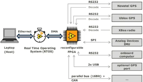
cm), it has the advantage that it combines a FPGA and a RTOS processor on one board. The FPGA allows for a very fast and par-allel data processing of any possible interface. Furthermore, the FPGA is reconfigurable. Thus, all the implemented interfaces can be changed easily. Especially during a prototyping this property is very helpful. Due to the fast data handling, the FPGA also en-ables an efficient preprocessing of the data, such as filtering the IMU observations or decoding the GPS messages. In Figure 3 the implemented interfaces of the direct georeferencing system are shown. According to that, the FPGA decodes the GPS data of the Novatel OEM board, the u-blox receiver and the data of the master station that is received by the XBee radio module. Fur-thermore, an interface to the IMU, the onboard computer and a few optional interfaces are implemented.
The position and attitude determination happens on the RTOS, which is running on a 400 MHz ARM processor. The data
com-Figure 3: The data links of the direct georeferencing system.
munication between the FPGA and the RTOS processor occurs by a direct memory access (DMA). Thus, the preprocessed data of the sensors is directly written into the main memory, without detours using the processors. In this way running processes will not be disturbed during data transfers, which is very important for real-time processing.
By use of an Ethernet connection an insight into the system is possible. According to that, users can monitor the processes run-ning. Therefore, a graphical user interface was implemented. Finally, the direct georeferencing system was primary developed to be applicable in lightweight UAVs. However, the design of the system was explicitly carried out to allow for an application of this hardware on any kind of mobile platform as well.
2.3 UAV platform
Generally many different UAV platforms exist on the market, such as fixed wing aircrafts, blimps, helicopters, paragliders or
multicopters (Everaerts, 2008). The goal of the projectMapping on Demandis to identify and measure three-dimensional objects. Therefore, our platform has to be able to reach objects fast, but approach objects slowly or even to hover (fly on the spot). This can only be done by a helicopter or a multicopter. Since mul-ticopters are easier to control than helicopters, we decided to choose a multicopter as UAV.
Our system is based on the construction kit ”Mikrokopter Oc-toXl”, sold by the company HiSystems GmbH (HiSystems, 2013). We applied several modifications to the original setup. (1) The centerplates, which hold the frame together, were exchanged with more stable 2 mm CFK plates, to reduce the influence of the ro-tor vibrations. (2) Two roro-tors were turned over. This was done to attach the single-frequency antenna of the u-blox GPS receiver at the end of one of the riggers. (3) A shelf was added in the middle of the frame. This construction is intended to provide space for the onboard processing units and two lithium-polymer batteries. The modified UAV is shown in Figure 4. In this graphic all the
Figure 4: The UAV together with all the onboard mounted hard-ware.
additional hardware is already mounted on the platform. Besides the direct georeferencing hardware also a high-resolution camera, an onboard computer for the image processing and a WiFi module for the communication with a ground station are highlighted. All sensors are tightly mounted on the platform to ensure that they have constant lever arms during flights. One of the stereo cam-era systems looks forward, the other one is looking backwards. The dual-frequency GPS antenna is mounted in the middle of the frame, the single-frequency GPS antenna is attached on a lateral rigger. Thus, the onboard GPS baseline allows for the determina-tion of the yaw and the roll of the aircraft.
The weight of the UAV including the additional hardware is 4.8 kg, without optimization. Thus, it is below the weight limit of 5 kg that is regulated by German law. Currently, the UAV is controlled manually. Therefore, a RC transmitter is used. In future, the UAV shall fly autonomously. In this case, the onboard computer will act as navigation unit, too.
3 SOFTWARE DEVELOPMENT
In this section an overview of the methodology for the position and attitude determination software as well as the implementa-tion aspects will be given. Generally, the FPGA and the RTOS programming is done by use of LabViewTM
. LabViewTM
is a de-velopment environment for a visual programming language from National InstrumentsTM, which is very useful for the development
3.1 The RTK-GPS software
RTK-GPS is the most suitable procedure to obtain kinematic GPS positions with cm-level of accuracy in real-time. It is a DGPS technique, based on the observations of at least two receivers. Thus, the aim of this approach is to determine the position of the rover antenna relative to the position of the master antenna. In case of GPS-positioning, the master antenna normally remains fixed, while the rover antenna is moving. In contrast to normal DGPS precise carrier phase observations must be used for RTK-GPS in order to allow for cm-level accuracy. Since the RTK-GPS re-ceivers only observe phase differences (fractional part), while the number of integer cycles (integer part) is a priori unknown, the so called ambiguity resolution (AR) is the key to RTK-GPS posi-tioning. The performance of the AR is very important. The rea-son is that every loss of lock of the GPS signals requires a reini-tialization of the ambiguities. In kinematic applications losses of locks occur very often. Therefore, the AR has to be fast, but ro-bust at the same time.
We decided to implement our own RTK-GPS software. The rea-son is that (1) not all GPS receivers provide a RTK-GPS solution, (2) RTK-GPS software on the receiver controller is generally still expensive, (3) our goal is a fast AR and (4) we use a multi-sensor system on our platform so that we aim for improving the GPS solution in a tightly coupled system.
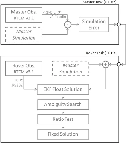
Our RTK-GPS software works in two parallel tasks (see Fig-ure 5). The master task and the rover task. The RTK-GPS pro-cessing happens in the rover task with a rate of 10 Hz and is based on code and carrier-phase observations measured at the rover and the master receiver. The data format used for transmission of the GPS raw data is the RTCM v3.1 format. Since the master sta-tion remains on the ground, the master observasta-tions have to be transmitted via radio to the direct georeferencing system. The
Figure 5: The data links of the direct georeferencing system.
transmission rate is 1 Hz. So as not to be dependent on the unre-liable master data transmission and the lesser sampling rate, not the real master observations, but simulated master observations are used as input for the RTK-GPS processing. This simulation is based on the fixed and known coordinates of the master antenna,
the satellite broadcast ephemeris as well as the time for which the simulation is applied (Mohino et al., 2005). The true master ob-servations are only used to update the simulation error that has to be adapted to correct the simulation results.
After the observations are generated, the RTK software performs the following steps: (1) the float solution by means of an extended Kalman filter (EKF), (2) the ambiguity search, (3) the ratio test and (4) the fixed solution.
The float solution is the step where the ambiguity parameters are estimated as real values. To allow for a fast AR code and carrier-phase observations are used for that. The float estimation can be computed in a single-epoch least-squares adjustment (LSA) or an EKF. Both, the LSA as well as the EKF generally enable a single-epoch ambiguity resolution. While the LSA is often faster, the EKF also allows for an AR during poor measurement condi-tions. That is why we mostly use the EKF, even if the LSA is also implemented in our software.
In the second step, the float ambiguities and their covariance matrix are used to search for the integer ambiguities. This is done by a combination of the least squares decorrelation adjust-ment (LAMBDA) (Teunissen, 1995) and the modified LAMBDA (MLAMBDA) method (Chang et al., 2005), which is a little faster for a large number of observations.
After the ambiguity search a decision must be made, if the result-ing set of ambiguities can be accepted or if it has to be rejected, since there is the risk that the result from the ambiguity search is incorrect. This decision is made by the ratio test. In the ratio test, the best and the second best set of ambiguities are compared and only if the difference exceeds a predefined threshold, the res-olution can be accepted. In case the ambiguities could be fixed successfully, the most precise fixed solution can be computed. In case the ambiguities had to be rejected, the less precise float so-lution has to be provided.
The computation time of the complete RTK-GPS processing on the direct georeferencing system is less than 0.05 s. Thus, it al-lows for a processing rate of 20 Hz.
3.2 The attitude determination
Generally, there are three levels of quality, by which the attitudes of the UAV can be determined with the direct georeferencing sys-tem. (1) The attitude determination is only done by use of the IMU and the magnetic field sensors. (2) The attitude determina-tion is done by use of the IMU and the onboard GPS baseline. (3) The stereo camera data is also integrated.
Currently, the attitude determination happens by (1). Thus, the gyroscopes, the accelerometers and the magnetic field sensors of the IMU are used to determine the yaw, pitch and roll angles of the UAV. The sensors are fused in a quaternion based EKF. In this filter, the four quaternion parameters and also the gyro biases are estimated (see e.g. (Sabatini, 2006)).
Since the magnetometer is the only sensor that provides an abso-lute yaw information, it is very important in this way of attitude determination. However, magnetic field sensor measurements are distorted by hard iron and soft iron effects. While hard iron dis-tortions arise from permanent magnets and magnetized iron or steel on the compass platform, soft iron distortion arises from any magnetically soft material surrounding the compass (Caruso, 2000). To reduce the effect of magnetic distortion, the compass has to be calibrated carefully.
with running engines in different operating states, which is very difficult to realize. Therefore, the accuracy of the magnetometer is approximately 2 deg during flights, which does not meet the requirements of less than 0.5 deg. On this account, an additional sensor is needed to allow for a precise and reliable attitude deter-mination.
Together with the dual-frequency GPS antenna, the antenna of the single-frequency receiver embodies a short baseline on the UAV. Thus, by use of the second onboard GPS-receiver (u-blox LEA-6T), a direct attitude determination is possible. Generally, the GPS-attitude determination happens in a similar way as the RTK-GPS solution. Thus, the carrier-phase observations are used to determine the relative baseline parameters. For that an ambigu-ity resolution is required as well. By comparison to the RTK-GPS solution there are some differences in the GPS attitude determi-nation: (1) the baseline is moving, thus master and rover observa-tions are required for every epoch, (2) the attitude determination is only based on L1 observations, (3) the baseline is a lot shorter so that systematic observation errors are very similar at both an-tennas with the result that they can be canceled out and (4) the baseline length remains constant.
Similar to the GPS-positioning, the key to the GPS attitude deter-mination is the AR. Since only L1 observations are available for that, the AR is more difficult. In order to overcome this difficulty additional information is needed to improve the time to first fix of the ambiguities for the attitude determination. Therefore, the known baseline-length and an approximate attitude information, determined by the IMU and the magnetometer, are used to reduce the size of the ambiguity search space (Eling et al., 2013). Un-fortunately, the software is not fully implemented on the RTOS, yet. Therefore, we can only show results of the level (1) attitude determination in the following section.
4 RESULTS
The direct georeferencing system has been tested in many field tests up to now. In this section the results of one of this flights will be shown to present the functionality of the system. The flight took place on an open field in Bonn. Besides the UAV and the direct georeferencing system a GPS master station, a lap-top and a RC transmitter were applied for this test. The laplap-top was used to monitor the states of the direct georeferencing system during the flight. The data connection between the laptop and the direct georeferencing system was realized by a WiFi module.The GPS master station was positioned 10 m next to the starting place, to provide dual frequency GPS observations to the onboard sys-tem. Due to this short distance the determined RTK-GPS base-lines were also relatively short (<60 m). During the complete test there were no long term signal interruptions of the radio con-nection to the master station. Within approximately six minutes manual flight different maneuvers were carried out. The positions and attitudes were determined in real-time and logged on a USB device.
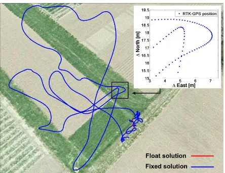
In this test the ambiguities were reinitialized in every epoch. This was done to demonstrate how well the ambiguity resolution algo-rithm of our software works. In normal applications, the ambigu-ities can be hold fixed, as soon as they are initialized and as long as no cycle slips occurred. In Figure 6 the results of the position determination are shown.
The ambiguities have already been solved in the first epoch of the test. Float solutions occurred, in epochs, where the ambiguities could not be solved. In Figure 6 and in the heights plot (see Fig-ure 7) the float solutions are marked in red, while the fixed solu-tions are marked with blue lines/green dots. Altogether, in 3327 epochs the ambiguities could be fixed in 3246 epochs (97.5%).
Figure 6: The RTK-GPS positions that were determined during the test flight. The red points are float solutions (real valued ambi-guities), the blue points are fixed solutions (integer ambiguities).
Only in 81 epochs, mostly in the starting and landing area, float solutions were provided by the software.
The determined attitudes are presented in Figure 7. Mostly, the UAV showed in the same direction during the flight. Thus, the at-titude changes in the yaw angle are only in a magnitude of about 40 deg. As expected, the roll and the pitch of the UAV are rela-tively small with a maximum of 10 deg and a minimum of -8 deg. To reduce the impact of the rotor vibrations a low-pass filter was used to eliminate high-frequency signals in the IMU data. With-out this filter the distortion of the attitudes would be huge and clearly visible. Currently, the authors are working on the opti-mization of the low-pass filter and the orientation determination algorithm.
To illustrate the precision of the RTK-GPS positions an enlarged view of a section of the height time series is presented in Figure 8. Since this is a static part of the test, the noise of the GPS heights becomes apparent. Together with the experience from other tests, the precision of the positions can be specified to 1 cm for the hor-izontal and 2 cm for the vertical components, when the ambigui-ties are fixed. In comparison with other recognized GPS software packages (e.g. RTKLIB (Takasu and Yasuda, 2009)), the correct-ness of the RTK-GPS software was also confirmed. As soon as the fusion of the GPS data with other sensors such as the IMU is realized on the direct georeferencing system a comparison of the positions and attitudes to a reference solution will follow.
Summarizing, in this section it could be shown that the direct geo-referencing system is already applicable. Positions and attitudes of an UAV can be determined in real-time. Especially the RTK-GPS solution allows for high position accuracies in the range of a few centimeters.
5 CONCLUSIONS AND FUTURE WORK
In this contribution a new developed direct georeferencing system has been presented. The system combines GPS, inertial sensors, magnetic field sensors, a barometer and cameras. The main ad-vantages of the system are that (1) it is lightweight, (2) it is real time capable, (3) it leads to precise results and (4) it is able to bridge gaps of single sensors.
Figure 7: The height of the UAV is presented in the upper graph. In this, fixed solutions (integer ambiguities) are printed in green, while float solutions (real valued ambiguities) are printed in red. The bottom graph shows the roll, pitch and yaw angle of the UAV during the test flight.
Figure 8: An enlarged view of the marked section of the height time series, which is shown in Figure 7.
The authors are currently working on the integration of the on-board GPS baseline in the attitude determination as it has been mentioned in this contribution. This combination will enormously improve the attitude accuracy. In future, a fusion of the GPS posi-tions with the data of the inertial sensors and the optical flow from the stereo video cameras will be implemented. The challenge of this fusion will be the consideration of the latency time of the po-sition and attitude changes from the camera systems with respect to the GPS and IMU data. Furthermore, the IMU will also be used for cycle slip detection and repair in the GPS processing to improve the reliability of the RTK-GPS solution.
ACKNOWLEDGEMENTS
This research project would not have been possible without the fi-nancial support of the DFG (Deutsche Forschungsgemeinschaft) (project number 1505 ”Mapping on Demand”). The authors wish to express their gratitude for that.
REFERENCES
Caruso, M. J., 2000. Applications of magnetic field ssensor for low cost compass systems. In: IEEE Position, Location and Nav-igation Symposium, pp. 177–184.
Chang, X.-W., Yang, X. and Zhou, T., 2005. Mlambda: a modi-fied lambda method for integer least-squares estimation. Journal of Geodesy 79, pp. 552–565.
Eisenbeiss, H., Lambers, K. and Sauerbier, M., 2005. Pho-togrammetric recording of the archaeological site of pinchango
alto (palpa, peru) using a mini helicopter (uav). In: A. Figueiredo and G. Velho (eds), The World is in Your Eyes - Proceedings of the 33rd CAA Conference.
Eling, C., Zeimetz, P. and Kuhlmann, H., 2013. Development of an instantaneous gnss/mems attitude determination system. GPS Solution 17, pp. 129–138.
Everaerts, J., 2008. The use of unmanned aerial vehicles (uavs) for remote sensing and mapping. In: Proceeding of ISPRS, The International Archives of the Photogrammetry, Remote Sensing and Spatial Information Sciences. Vol. XXXVII. Part B1, Beijing, pp. 1187–1191.
HiSystems, 2013. Hisystems gmbh, the mikrokopter shop, url: www.mikrocontroller.com.
Merz, T. and Kendoul, F., 2011. Beyond visual range obstacle avoidance and infrastructure inspection by an autonomous he-licopter. In: IEEE/RSJ International Conference on Intelligent Robots and Systems, IROS 2011, San Francisco, USA.
Mohino, E., Gende, M., Brunini, C. and Heraiz, M., 2005. Sigog: simulated gps observation generator. GPS Solution 9, pp. 250– 254.
Nagai, M., Chen, T., Shibasaki, R., Kumagai, H. and Ahmed, A., 2009. Uav-borne 3-d mapping system by multisensor integration. IEEE Transactions on Geoscience and 47(3), pp. 701–708.
Odijk, D., Traugott, J., Sachs, G., Montenbruck, O. and Tiberius, C., 2007. Two precision gps approaches applied to kinematic raw measurements of miniaturmini l1 receivers. In: Proceedings of the 20th International Technical Meeting of the Satellite Division of the Institute of Navigation ION GNSS 2007, pp. 827–838.
Rieke, M., Foerster, T., Geipel, J. and Prinz, T., 2011. High-precision positioning and real-time data processing of uav-systems. In: International Archives of the Photogrammetry, Re-mote Sensing and Spatial Information Sciences, Vol. XXXVIII (1-C22), UAV-g conference, Zurich, Switzerland.
Sabatini, A. M., 2006. Quaternion-based extended kalman fil-ter for defil-termining orientation by inertial and magnetic sensing. IEEE Transactions on Biomedical E 53(7), pp. 1346–1356.
Stempfhuber, W. and Buchholz, M., 2011. A precise, low-cost rtk gnss system for uav applications. In: International Archives of the Photogrammetry, Remote Sensing and Spatial Information Sciences, Vol. XXXVIII (1-C22), ISPRS Zurich 2011 Workshop, Zurich, Switzerland, pp. 289–293.
Takasu, T. and Yasuda, A., 2009. Development of
the low-cost rtk-gps receiver with an open source pro-gram package rtklib. In: International Sympoisum on GPS/GNSS, International Convention Center Jeju, Korea. RTKLIB: An Open Source Program Package for RTK-GPS, http://gpspp.sakura.ne.jp/rtklib/rtklib.htm.
Teunissen, P. J. G., 1995. The least-squares ambiguity decorrela-tion adjustment: a method for fast gps integer ambiguity estima-tion. Journal of Geodesy 70, pp. 65–82.
Xiang, H. and Tian, L., 2011. Development of a low-cost agricul-ture remote sensing system based on an autonomous unmanned aerial vehicle (uav). Biosystems Engineering 108, pp. 174–190.
Yoo, C. and Ahn, I., 2003. Low cost gps/ins sensor fusion sys-tem for uav navigation. In: The 22nd Digital Avionics Syssys-tems Conference, Vol. 2, pp. 8.A.1–1 – 8.A.1–9.