DENSE TRACKING AND MAPPING WITH A QUADROCOPTER
J. Sturma,∗, E. Bylowb, C. Kerla, F. Kahlb, and D. Cremersa
a
Computer Vision Group, Department of Computer Science, Technical University of Munich, Germany {juergen.sturm,christian.kerl,cremers}@in.tum.de
b
Mathematical Imaging Group, Centre for Mathematical Sciences Faculty of Engineering, Lund University, Sweden [email protected], [email protected]
KEY WORDS:quadrocopter, localization, 3D reconstruction, RGB-D sensors, real-time
ABSTRACT
In this paper, we present an approach for acquiring textured 3D models of room-sized indoor spaces using a quadrocopter. Such room models are for example useful for architects and interior designers as well as for factory planners and construction man-agers. The model is internally represented by a signed distance function (SDF) and the SDF is used to directly track the camera with respect to the model. Our solution enables accurate position control of the quadrocopter, so that it can automatically follow a pre-defined flight pattern. Our system provides live feedback of the acquired 3D model to the user. The final model consisting of a textured 3D triangle mesh can be saved in several standard CAD file formats.
1 INTRODUCTION
The ability to quickly scan a 3D model of a room or factory floor has many potential applications: For example, craftsmen can read of from such room models the size of a window or its height di-rectly from the model. Furthermore, interior designers can illus-trate the effects of decoration using such models, and potential buyers of an apartment can get a better impression of the real es-tate. While we recently demonstrated that scanning a room with a hand-held sensor is feasible (Bylow et al., 2013), quadrocopter-based scanning has several advantages: First, scanning can be performed fully automatically and no human intervention is re-quired. Second, it is possible to scan larger rooms (for example, industrial production halls) from above which might not be pos-sible from the ground. Third, it is pospos-sible to use quadrocopters to scan inaccessible or dangerous buildings, e.g., after an earth-quake.
In this paper, which is an extension of our recent work (Bylow et al., 2013), we first present our approach on 3D scanning using an RGB-D camera that (1) provides accurate pose information in real-time and (2) estimates a dense, textured 3D model of the scene. We demonstrate that our approach is fast, accurate, and robust enough to control the position of a quadrocopter and thus to generate a dense 3D model of a room fully automatically. Our approach relies on an RGB-D camera that yields dense depth im-ages at video frame rate. While our current implementation relies on GPU support provided by an external ground station, we are working towards a scalable CPU implementation that will allow us to perform all computations onboard the quadrocopter.
While feature-based approaches to the structure-from-motion prob-lem can be successfully applied to quadrocopter imagery and control, the resulting feature maps are typically sparse and thus not well suited for a visually pleasant 3D reconstruction (Agarwal et al., 2009, Weiss et al., 2012, Engel et al., 2012). Therefore, we advocate to represent the scene geometry in a dense grid using
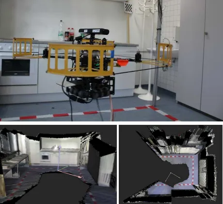
Figure 1: We present an efficient method for 3D reconstruction of indoor scenes using a quadrocopter equipped with an RGB-D camera. Top: AscTec Pelican platform used in our experiments. Bottom: Two different views on the reconstructed 3D model of our lab space.
a truncated signed distance function (Curless and Levoy, 1996) similar as in the famous KinectFusion approach (Newcombe et al., 2011). While KinectFusion uses ray tracing to generate a point cloud in each frame and the iterated closest point (ICP) algorithm for subsequent alignment, we present in this paper a novel method that allows us to directly compute the camera pose based on the signed distance function.The key idea behind our ap-proach is that the correct camera pose should minimize the value of the signed distance function evaluated at the back-projected points of the depth image. Furthermore, we fuse color informa-tion in an addiinforma-tional 3D voxel grid to generate a texture for the model. Figure 1(bottom) shows two views on the model acquired in this way from our lab space.
on a publicly available benchmark (Sturm et al., 2012). We found that our algorithm outperforms the KinectFusion implementation of the point cloud library (PCL)1in terms of accuracy and robust-ness. Furthermore, we found that our approach yields a compa-rable performance in comparison to the RGB-D SLAM system (Endres et al., 2012). In contrast to these methods, our solution outputs a color-textured 3D model of the scene and is signifi-cantly faster.
This paper is an extension of our recent work (Bylow et al., 2013) in which we provide a more detailed evaluation of our quadro-copter experiments. In particular, we measured the position ac-curacy of a quadrocopter while hovering and path following using our approach. Furthermore, we provide additional scans that we acquired using the quadrocopter.
2 RELATED WORK
Simultaneous localization and mapping refers to both the estima-tion of the camera pose and mapping of the environment. This requires a suitable representation of the scene geometry, and the choice of this representation strongly influences the efficiency of pose estimation and map optimization.
Laser-based localization and mapping approaches often use scan matching or the iterated closest point algorithm (ICP) (Besl and McKay, 1992) to estimate the motion between frames. Graph SLAM methods use these motion estimates as input to construct and optimize a pose graph (K¨ummerle et al., 2011). Typically, these methods render a joint map only after pose graph tion, and this map is generally not used for further pose optimiza-tion. The resulting maps are often represented as occupancy grid maps or octrees (Wurm et al., 2010) and are therefore well suited for robot localization or path planning. (Henry et al., 2010) were the first to apply the Graph SLAM approach to RGB-D data us-ing a combination of visual features and ICP. A similar system was recently presented by (Endres et al., 2012) and extensively evaluated on a public benchmark (Sturm et al., 2012). In this paper, we compare the performance of our approach to the RGB-D SLAM system and demonstrate that we achieve more detailed reconstructions and higher frame rates at a comparable pose ac-curacy.
(Newcombe et al., 2011) recently demonstrated with their famous KinectFusion approach that dense reconstruction is possible in real-time by using a Microsoft Kinect sensor. To represent the geometry, Newcombe et al. employ a signed distance function (SDF) (Curless and Levoy, 1996) and use ICP in a coarse-to-fine manner to estimate the camera motion. For each image, the al-gorithm first renders a point cloud from the SDF at the previous pose using ray tracing and subsequently aligns this with the next depth image. Point correspondences are found using projective data association (Blais and Levine, 1993) and the point-to-plane distance (Chen and Medioni, 1992). As the original implementa-tion is not available and no benchmark evaluaimplementa-tion is provided, we compare our approach to the KinFu open-source implementation as available in the point cloud library (KinectFusion Implemen-tation in the Point Cloud Library (PCL), n.d.). We show in this paper that our approach outperforms KinFu in terms of speed and accuracy.
While ICP only minimizes the error on point clouds, several ap-proaches have recently appeared that minimize the photometric error (Steinbr¨ucker et al., 2011) or combinations of both (Tykk¨al¨a
1
http://svn.pointclouds.org/pcl/trunk/
et al., 2011), however without subsequent 3D reconstruction. (Whe-lan et al., 2012) recently integrated these methods with the Kinect-Fusion approach and demonstrated that superior tracking perfor-mance can be achieved, however without evaluating the global consistency of the resulting model.
While our approach on dense tracking and 3D reconstruction was first introduced in (Bylow et al., 2013), we provide in this paper a more in-depth evaluation of the resulting accuracy and stability when used with an autonomous quadrocopter. In particular, we evaluate the accuracy of keeping a particular position and follow-ing a pre-defined scannfollow-ing trajectory. Furthermore, we provide scans from additional scenes to demonstrate its robustness and applicability in practice.
3 QUADROCOPTER-BASED 3D MODEL
ACQUISITION
In this section, we explain how we acquire the 3D model of a room using an RGB-D camera mounted on a quadrocopter. As our approach currently requires a GPU to achieve real-time pro-cessing, we connected the RGB-D camera directly to a work sta-tion using a USB cable and perform all computasta-tions off-board. The estimated camera pose is then sent back to the quadrocopter and used for data fusion and position control which runs onboard the quadrocopter.
3.1 Live Dense 3D Reconstruction
In the following, we briefly explain how we track the camera pose and generate the dense 3D model. We kept this section inten-tionally short and refer the interested reader to (Newcombe et al., 2011, Bylow et al., 2013) for more details on signed distance functions, the KinectFusion algorithm, and our recent extensions.
Preliminaries In each time step, we obtain a color image and a depth image from the Kinect sensor, i.e.,
IRGB :R
2
→R3andIZ:R 2
→R. (1)
We assume that the depth image is already registered on to the color image, so that pixels between both images correspond. Fur-thermore, we require a signed distance function (SDF), a weight function, and a color function that are defined for each 3D point p∈R3within the reconstruction volume:
D:R3→R, W :R3→R, andC:R3→R3. (2)
The SDF represents the distance of each point to the closest sur-face, i.e., D(p) = 0holds for all points plying on surface, D(p) < 0for free space, andD(p) > 0for occupied space. In the following, we treatIRGB,IZ,D,W, andCas continuous
functions, but we represent them internally as discrete pixel/voxel grids (of size 640×480 and 256×256×256, respectively). When access to a non-integer value is needed, we apply bi-/tri-linear in-terpolation between the neighboring values. We assume the pin-hole camera model, which defines the relationship between a 3D pointp= (x, y, z)⊤∈ ter of the camera, respectively. In reverse, given the depthz =
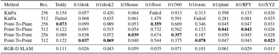
Table 1: The root-mean square absolute trajectory error for KinFu and our method for different resolutions, metrics and datasets. Also the result for RGB-D SLAM are presented. More details on this evaluation can be found in (Bylow et al., 2013).
Method Res. Teddy fr1/desk fr1/desk2 fr3/house fr1/floor fr1/360 fr1/room fr1/plant fr1/RPY fr1/XYZ
KinFu 256 0.154 0.057 0.420 0.064 Failed 0.913 0.313 0.598 0.133 0.026 KinFu 512 Failed 0.068 0.635 0.061 1.479 0.591 Failed 0.281 0.081 0.025 Point-To-Plane 256 0.073 0.099 0.089 0.053 0.359 0.669 0.346 0.045 0.047 0.031 Point-To-Plane 512 0.122 0.091 0.515 0.054 0.732 0.562 0.123 0.041 0.043 0.026 Point-To-Point 256 0.089 0.038 0.072 0.039 0.674 0.357 0.187 0.050 0.045 0.028 Point-To-Point 512 0.122 0.037 0.069 0.040 0.544 0.375 0.078 0.047 0.043 0.023
RGB-D SLAM 0.111 0.026 0.043 0.059 0.035 0.071 0.101 0.061 0.029 0.013
3D point using
In each time step, we first estimate the current camera poseξ given the current depth imageIZand SDFD, and subsequently integrate the new data into the voxel grids. We represent the cur-rent camera pose using twist coordinates, i.e.,
ξ= (ω1, ω2, ω3, v1, v2, v3)∈R6. (5)
These Lie algebra coordinates form a minimal representation and are well suited for numerical optimization. Twist coordinates can be easily converted to a rotation matrixR∈R3×3and translation vectort∈R3(and vice versa) when needed (Ma et al., 2003).
Finally, we assume that the noise of the Kinect sensor can be modeled with a Gaussian error function, i.e.,
p(zobs|ztrue)∝exp −(ztrue−zobs)2 /σ2
. (6)
In principle, the noise of the Kinect (and any disparity-based dis-tance sensor) is quadratically proportional to the disdis-tance, i.e., σ∝z2
true. However, in our current implementation, we assume a fixedσover all pixels.
Camera pose estimation Given a new depth imageIZand our current estimate of the SDFD, our goal is to find the camera pose ξthat best aligns the depth image with the SDF, i.e., each pixel of the depth image should (ideally) map onto the zero crossing in the signed distance function. Due to noise and other inaccuracies, the depth image will of course never perfectly match the SDF (nor will our estimate of the SDF be perfect). Therefore, we seek the camera pose that maximizes the observation likelihood of all pixels in the depth image, i.e.,
p(IZ|ξ, D)∝ the reconstructed 3D point to keep our notation uncluttered. Note that a circular motion constraint is not imposed in the estimation process. By taking the negative logarithm, we obtain
L(ξ)∝X i,j
D(Rxij+t) 2
. (8)
To find its minimum, we set the derivative to zero and apply the Gauss-Newton algorithm, i.e., we iteratively linearizeD(Rxij+ t)with respect to the camera poseξat our current pose estimate and solve the linearized system.
Note that KinectFusion pursues a different (and less effective) approach to camera tracking, as it first extracts a second depth
image from the SDF that it then aligns to the current depth im-age using the iteratively closest point algorithm (ICP). As this requires an intermediate data association step between both point clouds, this is computationally more involved. Furthermore, the projection of the SDF onto a depth image looses important infor-mation that cannot be used in the iterations of ICP. To evaluate the performance of both approaches, we recently compared (Bylow et al., 2013) our approach with the free KinFu implementation in PCL2 on publicly available datasets (Sturm et al., 2012). The results are presented in Tab. 1 and clearly show that our approach is significantly more accurate.
Updating the SDF After the current camera pose has been es-timated, we update the SDFD, the weightsW, and the texture Csimilar to (Curless and Levoy, 1996, Bylow et al., 2013). We transform the global 3D coordinatesp= (x, y, z)⊤
Asdobsis not the true distance but an approximation,dobsgets increasingly inaccurate the further we are away from the surface. Furthermore, the projective distance is inaccurate when the view-ing angle is far from 90◦onto the surface as well as in the vicinity of object boundaries and discontinuities. Therefore, we follow the approach of (Curless and Levoy, 1996) by truncating the dis-tance function at a value ofδand defining a weighting function to express our confidence in this approximation:
d(dobs) =
A visualization of these functions is given in Fig. 2.
2
distance from surfacedobs d w
Experimentally, we determinedδ = 0.3mto work well for our application. To interpret this number, notice thatδexpresses our prior about the average thickness of objects in the scene. As our primary objects of interest are things such as walls, cabinets, chairs, and tables, such a prior seems reasonable. In our experi-ments, we found that largerδlead to more stable tracking but less accurate reconstructions, while smallerδgenerally lead to more accurate reconstructions with more details, but reduced stability, i.e., a diverging map after jumps in the flight behavior. We be-lieve that this instability can be explained as follows: Imagine the quadrocopter has built up the SDF up to a distance ofδfrom the observed surface. When the quadrocopter now jumps forward by a distance ofδ, the SDF does not contain any useful information anymore to recover the camera pose. In our flight experiments, we observed (occasionally) translational jumps of up to 0.08m, so thatδ= 0.3mis a reasonable choice.
We update each voxel cell with (global) 3D coordinates(x, y, z)⊤ according to
D←(W D+wd)/(W+w), (12) C←(W C+wc)/(W+w), (13)
W ←W+w, (14)
wherec=IRGB(π(x′, y′, z′))is the color from the RGB image.
Both steps (the estimation of the camera pose and updating the voxel grids) can be easily parallelized using CUDA. With our current implementation, the computation time per frame is ap-proximately 27ms on a Nvidia GeForce GTX 560 with 384 cores, and runs thus easily in real-time with 30fps.
Visualization With the algorithm described above, we obtain an estimate of the signed distance and color for every cell of the voxel grid. To display this model to the user, we copy the data every two seconds from the GPU to the CPU (which consumes 60ms) and run a threaded CPU implementation of the marching cubes algorithm (Lorensen and Cline, 1987). The mesh gener-ation takes around between 1000 and 1500ms on a single CPU core. The resulting triangle mesh typically consists of approx-imately 200.000–500.000 vertices (and faces), that we display together with the estimated camera trajectory to the user using OpenGL.
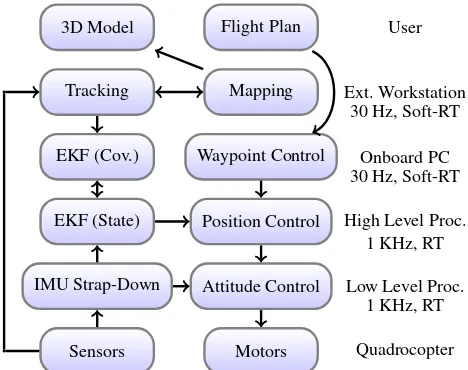
Quadrocopter Control Figure 3 shows the flow diagram of the control architecture used in our approach (Weiss et al., 2012). The low level processor (LLP) provides the attitude control for the platform. The high level processor (HLP) runs the extended Kalman filter and position/velocity control at 1KHz, and accepts velocity commands and waypoints. The error controller is a LQR controller for each axis. The feed forward model allows the quadro-copter to quickly reach the waypoint and reduces overshoot. It is possible to specify the approach speed and accuracy with which the quadrocopter should reach the goal location. The onboard PC running ROS supplies the HLP with the visual pose estimates and waypoints at 30Hz. The dense tracking and 3D reconstruc-tion module runs on an external workstareconstruc-tion with a GPU that is directly connected to the RGB-D camera on the quadrocopter and the onboard PC.
4 QUADROCOPTER EXPERIMENTS
In this section, we present the results of our experiments evalua-tion. First, we provide an evaluation of the flight stability and ac-curacy when the quadrocopter is controlled using the poses from our approach. Second, we present and discuss the 3D models that we obtained in different indoor environments using our approach.
3D Model Flight Plan User
Tracking Mapping Ext. Workstation
EKF (Cov.) Waypoint Control Onboard PC
EKF (State) Position Control High Level Proc.
IMU Strap-Down Attitude Control Low Level Proc.
Sensors Motors Quadrocopter
30 Hz, Soft-RT
30 Hz, Soft-RT
1 KHz, RT
1 KHz, RT
Figure 3: Control architecture used by our approach. The quadro-copter has three processors that operate at different cycle times.
4.1 Flight Accuracy
In all of our experiments, we initialized the map with the quadro-copter standing on the ground. From then onward, the visual pose estimate from our approach is fed into the EKF and used for po-sition control. To initiate take-off, we send a positive velocity in z-direction to the position controller. After the quadrocopter reaches a certain height, we switch to waypoint control.
In our first experiment, we started the quadrocopter as described and commanded a single way point as its goal location. Figure 4 shows the result. As can be seen from this plot, the quadrocopter is able to accurately maintain the desired goal location. In partic-ular, we measured an average standard deviation of 2.1cm during hovering.
In our second experiment, we provided a rectangle as the flight plan to the quadrocopter. As can be seen from Fig. 5, the quadro-copter closely follows the generated waypoints. Furthermore, we could repeat this procedure for several minutes without noticing any degradation of the 3D model or the flight stability.
4.2 3D Scans
We used our approach to scan three different rooms to verify the stability, robustness, and applicability of our approach.
The first room, shown in Fig. 1, is our quadrocopter lab. It has a kitchen unit in front, several cabinets with little structure and texture on the right, and tables on the left. The quadrocopter per-formed an autonomous take-off and followed a pre-defined mo-tion along a half-circle. As can be seen from the two images in the bottom row, the reconstructed 3D model provides a good impression of the scene. An architect or interior designer could clearly use this model to measures the size of the room or other distances. Furthermore, as can be seen from the top-down view, there is only little drift: The opposing walls (which have never been observed simultaneously) are mostly parallel.
Furthermore, we scanned a normal office in our lab with four workspaces, see Fig. 6. Here, we sent a different flight pattern to the robot, consisting of a rectangular motion in combination with a 270◦
−0.2
−0.1
0
−0.1 0
0.1 0.3 0.35 0.4 0.45 0.5
x [m] y [m]
z
[m]
Figure 4: Hovering experiment using the position information from the proposed approach. The average deviation from the set point was 2.1cm. Blue: Estimated position of the quadrocopter. Red: Goal location.
−0.2
0
0.2
−0.2 0 0.2 0 0.2 0.4 0.6
x [m] y [m]
z
[m]
Figure 5: Path following experiment (rectangle). Blue: Estimated position of the quadrocopter. Red: Waypoints. As can be seen from this plot, the quadrocopter follows accurately and robustly the commanded trajectory for several rounds.
Figure 6: Office space with four desks scanned with our quadro-copter. The quadrocopter followed a pre-defined flight plan (rect-angle and rotations) to acquire the 3D model. Top: Image from external camera. Bottom: Reconstructed 3D models from side view and top view. The coordinate axes correspond to the esti-mated trajectory.
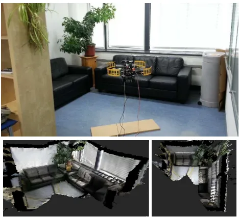
Finally, we scanned the couch space in our lab as shown in Fig. 7. In this experiment, we used the assisted flight mode, i.e., a pilot specified the waypoint manually with the remote control, while the quadrocopter used the estimated pose to approach this pose. This mode has the advantage that this solution is more flexible, as the pilot can specify additional waypoints while the room is being scanned. In contrast to manual flight, the cognitive load of the pilot is greatly reduced as only a waypoint has to be specified and no control commands have to be issued.
5 CONCLUSION
In this paper, we have presented a novel technique to acquire high-quality 3D models of rooms using an autonomous quadro-copter. We incrementally construct a signed distance function of the scene and estimate the current camera pose with respect to the SDF. In our experiments, we demonstrated that camera pose estimation is fast, accurate, and robust enough to be used for posi-tion control of an autonomous quadrocopter. We acquired various 3D models of office rooms in our lab to demonstrate the validity of our approach. The resulting 3D models are valuable for vari-ous tasks, including interior design, architecture, or refurnishing work.
Despite these promising results, there are several aspects remain-ing for future work. First, we would like to investigate whether similar results can be obtained with stereo cameras. This would allow us to scan outdoor scenes, for example, on construction sites. Second, we are currently working on a CPU implemen-tation that can run in real-time (but at a reduced resolution) on board the quadrocopter. Third, we solely use the reconstructed 3D model at the moment to display it to the user. However, it could also be used during assisted flight, e.g., to avoid collisions. Moreover, it would be interesting to generate the next waypoint based on autonomous exploration using the partial map.
REFERENCES
Agarwal, S., Snavely, N., Simon, I., Seitz, S. and R.Szeliski, 2009. Building rome in a day. In: ICCV.
Besl, P. and McKay, N., 1992. A method for registration of 3-D shapes. IEEE Trans. Pattern Anal. Mach. Intell. 14(2), pp. 239– 256.
Blais, G. and Levine, M., 1993. Registering multiview range data to create 3D computer objects. IEEE Trans. Pattern Anal. Mach. Intell. 17, pp. 820–824.
Bylow, E., Sturm, J., Kerl, C., Kahl, F. and Cremers, D., 2013. Real-time camera tracking and 3d reconstruction using signed distance functions. In: RSS.
Chen, Y. and Medioni, G., 1992. Object modelling by registration of multiple range images. Image Vision Comput. 10(3), pp. 145– 155.
Curless, B. and Levoy, M., 1996. A volumetric method for build-ing complex models from range images. In: SIGGRAPH.
Endres, F., Hess, J., Engelhard, N., Sturm, J., Cremers, D. and Burgard, W., 2012. An evaluation of the RGB-D SLAM system. In: ICRA.
Engel, J., Sturm, J. and Cremers, D., 2012. Camera-Based Navi-gation of a Low-Cost Quadrocopter. In: IEEE/RSJ Intl. Conf. on Intelligent Robot Systems (IROS).
Henry, P., Krainin, M., Herbst, E., Ren, X. and Fox, D., 2010. RGB-D mapping: Using depth cameras for dense 3D modeling of indoor environments.
KinectFusion Implementation in the Point Cloud Library (PCL),
n.d.http://svn.pointclouds.org/pcl/trunk/.
K¨ummerle, R., Grisetti, G., Strasdat, H., Konolige, K. and Bur-gard, W., 2011. g2o: A general framework for graph optimiza-tion. In: ICRA.
Lorensen, W. E. and Cline, H. E., 1987. Marching cubes: A high resolution 3D surface construction algorithm. Computer Graph-ics 21(4), pp. 163–169.
Ma, Y., Soatto, S., Kosecka, J. and Sastry, S., 2003. An Invita-tion to 3D Vision: From Images to Geometric Models. Springer Verlag.
Newcombe, R., Izadi, S., Hilliges, O., Molyneaux, D., Kim, D., Davison, A., Kohli, P., Shotton, J., Hodges, S. and Fitzgibbon, A., 2011. KinectFusion: Real-time dense surface mapping and tracking. In: ISMAR, pp. 127–136.
Steinbr¨ucker, F., Sturm, J. and Cremers, D., 2011. Real-time visual odometry from dense rgb-d images. In: Workshop on Live Dense Reconstruction with Moving Cameras at ICCV.
Sturm, J., Engelhard, N., Endres, F., Burgard, W. and Cremers, D., 2012. A benchmark for the evaluation of RGB-D SLAM systems. In: IROS.
Tykk¨al¨a, T., Audras, C. and Comport, A., 2011. Direct iterative closest point for real-time visual odometry. In: Workshop on Computer Vision in Vehicle Technology at ICCV.
Weiss, S., Achtelik, M., Chli, M. and Siegwart, R., 2012. Versa-tile Distributed Pose Estimation and Sensor Self-Calibration for an Autonomous MAV. In: IEEE Intl. Conf. on Robotics and Au-tomation (ICRA).
Whelan, T., Johannsson, H., Kaess, M., Leonard, J. and McDon-ald, J., 2012. Robust tracking for real-time dense RGB-D map-ping with Kintinuous. Technical report, MIT.